 Open Access Article
Creative Commons Attribution 3.0 Unported Licence
Variational model for a rippled graphene sheet
Jabr Aljedani *ab,
Michael J. Chen
 a and
Barry J. Cox
 a
a
aSchool of Mathematical Sciences, University of Adelaide, Adelaide, Australia. E-mail: Jabr.aljedani@adelaide.edu.au
bFaculty of Applied Studies, King Abdulaziz University, Jeddah, Saudi Arabia
First published on 22nd April 2020
Abstract
The calculus of variations is utilised to study the behaviour of a rippled graphene sheet supported on a metal substrate. We propose a model that is underpinned by two key parameters, the bending rigidity of graphene γ, and the van der Waals interaction strength ξ. Three cases are considered, each of which addresses a specific configuration of a rippled graphene sheet located on a flat substrate. The transitional case assumes that both the graphene sheet length and substrate length are constrained. The substrate constrained case assumes only the substrate has a constrained length. Finally, the graphene constrained case assumes only the length of the graphene sheet is constrained. Numerical results are presented for each case, and the interpretation of these results demonstrates a continuous relationship between the total energy per unit length and the substrate length, that incorporates all three configurations. The present model is in excellent agreement with earlier results of molecular dynamics (MD) simulations in predicting the profiles of graphene ripples.
1 Introduction
Graphene is a two-dimensional sheet of carbon atoms bonded to each other in a planar hexagonal array. This two-dimensional structure endows graphene with many useful electronic and mechanical properties.1–7 These properties mean graphene is a highly promising material for constructing nanoelectromechanical systems.8,9 Graphene is hypothesised to be a biocompatible material since its bending stiffness is comparable with that of the lipid bilayers of the biological cells,10 and it has many other applications in gas separation,11 biomedicine,12 nitrogen reduction reaction,13 and metal-ion batteries.14 For example, popgraphene is a beneficial anode material in lithium-ion batteries with fast charge and discharge rates.15However, graphene does not always remain planar. For example, ripples are observed in suspended graphene sheets,16 as well as graphene on a substrate.17 Experimental studies find that the electronic properties of graphene can be affected by the range and height of these ripples.18,19 Gui et al.20 use first-principles calculations to predict the electronic properties of a rippled graphene sheet where a band gap opening is observed in the rippled graphene. They evaluate a direct band gap at 0.93 eV which indicates rippled graphene may be a highly tunable semiconductor. They also report that the band gap increases proportionally with ripple amplitude, which is the maximum distance between the graphene sheet and the substrate.
The pattern of ripples in graphene may be affected by a variety of factors, including temperature, substrate material, and the size of the graphene sheet. For example, suspended graphene remains flat with no ripples when the temperature is close to absolute zero, but ripples appear as the temperature increases.21 When a graphene sheet is placed on a substrate the amplitude of the ripples depends on the substrate properties such as roughness and interfacial van der Waals interactions.17 Moreover, the overall size of the graphene sheet has a significant impact on the amplitude of ripples, with the ripple amplitude increasing proportionally with the size of the sheet.22
The bending rigidity of graphene plays an important role in the conformation of ripples. Using density functional theory calculations, Wei et al.10 evaluate the bending rigidity of a single-layer graphene at 1.44 eV. They compare this result to earlier obtained values for the bending rigidity of graphene which range from 0.80 to 1.60 eV. To cover this range of values, we will consider various bending rigidities for the rippled graphene in the present paper.
The energies we consider when modelling ripples in graphene are the same as those considered when modelling a fold of graphene. Cox et al.23 develop a model which describes a graphene sheet folded onto itself where two energies are taken into account. The first is the elastic energy that arises when bending a graphene sheet which is represented mathematically by integrating the square of the line curvature over the length of the total curve and scaled by the bending rigidity of graphene. The second energy is the van der Waals (vdW) interaction between the flat section of the graphene layers, prescribed as the integral of a Heaviside unit step function multiplied by the vdW energy per unit area. An extension of the fold model was further developed by Dyer et al.24 where either a carbon nanotube of circular or elliptical cross section is encapsulated in the graphene fold. A comparison between MD simulations and the mathematical model shows excellent agreement between the two approaches in determining the fold shape.
In the following section, we formulate a general mathematical model of a single graphene ripple on a substrate. In Section 3 we non-dimensionalise this model and employ the calculus of variations assuming a fixed length (isoperimetric) constraint of both the rippled graphene sheet and the substrate. In Section 4 we relax the isoperimetric constraint on the sheet length, but maintain a fixed substrate length. The substrate length is varied in Section 5 and an isoperimetric constraint is applied to only the sheet length. The solutions and associated numerical details are provided with each case. The main results and the relationships between the three cases considered here are described in Section 6. Discussion and some concluding remarks are made in Section 7.
2 Model formulation
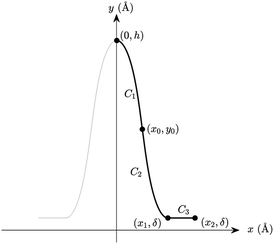
We propose a general formulation to determine the conformation of a rippled sheet of graphene on a substrate for each of the three cases mentioned above. We consider two different metal substrates: Cu(111) and Ni(111). The geometry of the rippled graphene sheet is shown in Fig. 1. Here we assume a translational symmetry in the z-direction which reduces the problem to two dimensions. Also, the reflective symmetry about the y-axis allows us to consider only solutions in the right half plane. We further divide the solution curve into three sections. The first section C1 is the curve from the point (0, h) to the point (x0, y0) where the line curvature is strictly negative. The second section C2 is from (x0, y0) to (x1, δ) where the line curvature is strictly positive. The third section C3 is the horizontal line from (x1, δ) to (x2, δ) where the line curvature is zero. The concatenation of these sections is denoted by C = C1 + C2 + C3. In these position vectors we use h to denote the ripple height, and δ to denote the separation distance between the substrate and the flat section of the graphene sheet.With reference to the model developed by Cox et al.,23 the dominant energies for our model are the elastic bending energy and the vdW interaction energy. The elastic energy Ee is modelled with
As mentioned in Section 1, the bending rigidity of graphene reported by various authors ranges from 0.8 to 1.6 eV as presented in ref. 10, and for the purpose of comparison we consider a linear sample from this range for γ, namely, 0.8, 1.0, 1.2, 1.4, and 1.6 eV. We model the vdW interaction energy between the graphene and the substrate as
 | (1) |
| x(0) = 0, y(0) = h, ẏ(0) = 0, y(x1) = δ, and ẏ(x1) = 0 | (2) |
For the purpose of comparison we prescribe a particular value of h for each case of a rippled graphene sheet supported on a different substrate, and the reason for adopting these particular values will be explained in Section 4. The prescribed ripple height, h, and empirical values for the separation distance between graphene and the substrate, δ, and the vdW energy of graphene–substrate interactions per unit area, ξ, corresponding to each substrate are shown in Table 1. Now we apply this model to consider the three cases for the length of graphene sheet placed on a substrate, namely, the transitional case, the substrate constrained case, and the graphene constrained case. Fig. 2 illustrates the geometry of each case.
 | ||
| Fig. 2 Schematic showing the geometries of: (a) the transitional case, (b) the substrate constrained case, and (c) the graphene constrained case. | ||
3 The transitional case
We now apply the calculus of variations to determine the conformation of a rippled graphene sheet and derive a solution for which the functional (1) is minimised. We impose an isoperimetric constraint on the total arc length of C, given byMoreover we assume that x2 is fixed, but x1 varies (to be determined from a natural boundary condition). Therefore the new functional we wish to minimise is of the form
 | (3) |
 | (4) |
Furthermore we subtract the fixed energy at X2, and divide both sides of eqn (4) by αξ. Thus we derive the nondimensionalised energy functional as
 | (5) |
 | (6) |
 | (7) |
Extremals of (6) are given by Euler–Lagrange equation
 | (8) |
 | (9) |
 | (10) |
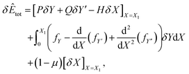
where P = fY′ − d(fY′′)/dX, Q = fY′′, and H = (Y′P + Y′′Q − f). Here the natural boundary condition, which applies when the X-coordinate at the end point X = X1 is not prescribed, requires H = (1 − μ). Therefore by combining eqn (9) and (10), we obtain
| βY′ + Y′′fY′′ − f = (1 − μ). |
Which after the substitution of (7) leads to
which is an equation relating the nondimensional curvature
![[small kappa, Greek, circumflex]](https://www.rsc.org/images/entities/i_char_e109.gif) and the first derivative of Y. In order to obtain the parametric solutions, we make the substitution of Y′ = tan
and the first derivative of Y. In order to obtain the parametric solutions, we make the substitution of Y′ = tan![[thin space (1/6-em)]](https://www.rsc.org/images/entities/char_2009.gif) θ which yields
θ which yields![[small kappa, Greek, circumflex]](https://www.rsc.org/images/entities/i_char_e109.gif) = ±[μ + (1 − μ)cos = ±[μ + (1 − μ)cos![[thin space (1/6-em)]](https://www.rsc.org/images/entities/char_2009.gif) θ − β θ − β![[thin space (1/6-em)]](https://www.rsc.org/images/entities/char_2009.gif) sin sin![[thin space (1/6-em)]](https://www.rsc.org/images/entities/char_2009.gif) θ]1/2. θ]1/2. |
The above expression may be written as follows
This leads to the succinct formula
![[small kappa, Greek, circumflex]](https://www.rsc.org/images/entities/i_char_e109.gif) = ±[μ + (1 − μ)sec = ±[μ + (1 − μ)sec![[thin space (1/6-em)]](https://www.rsc.org/images/entities/char_2009.gif) ψ ψ![[thin space (1/6-em)]](https://www.rsc.org/images/entities/char_2009.gif) cos(ψ + θ)]1/2. cos(ψ + θ)]1/2.
| (11) |
Now, using the fact that ![[small kappa, Greek, circumflex]](https://www.rsc.org/images/entities/i_char_e109.gif) = cos(θ)dθ/dX = sin(θ)dθ/dY, we derive two first order differential equations, namely
= cos(θ)dθ/dX = sin(θ)dθ/dY, we derive two first order differential equations, namely
 | (12a) |
 | (12b) |
To facilitate further integration we change the parametric variable of our equations from θ to ϕ such that θ = 2ϕ − ψ, thus eqn (12a) and (12b) take the following forms
 | (13a) |
 | (13b) |
X(ϕ) = c1 ± A[cos![[thin space (1/6-em)]](https://www.rsc.org/images/entities/char_2009.gif) ψ ψ![[thin space (1/6-em)]](https://www.rsc.org/images/entities/char_2009.gif) (E(ϕ,k) − BF(ϕ,k)) − sin (E(ϕ,k) − BF(ϕ,k)) − sin![[thin space (1/6-em)]](https://www.rsc.org/images/entities/char_2009.gif) ψ ψ![[thin space (1/6-em)]](https://www.rsc.org/images/entities/char_2009.gif) (1 − k2 (1 − k2![[thin space (1/6-em)]](https://www.rsc.org/images/entities/char_2009.gif) sin2 sin2![[thin space (1/6-em)]](https://www.rsc.org/images/entities/char_2009.gif) ϕ)1/2], ϕ)1/2], |
Y(ϕ) = c2 ∓ A[sin![[thin space (1/6-em)]](https://www.rsc.org/images/entities/char_2009.gif) ψ ψ![[thin space (1/6-em)]](https://www.rsc.org/images/entities/char_2009.gif) (E(ϕ,k) − BF(ϕ,k)) + cos (E(ϕ,k) − BF(ϕ,k)) + cos![[thin space (1/6-em)]](https://www.rsc.org/images/entities/char_2009.gif) ψ ψ![[thin space (1/6-em)]](https://www.rsc.org/images/entities/char_2009.gif) (1 − k2 (1 − k2![[thin space (1/6-em)]](https://www.rsc.org/images/entities/char_2009.gif) sin2 sin2![[thin space (1/6-em)]](https://www.rsc.org/images/entities/char_2009.gif) ϕ)1/2], ϕ)1/2], |
where F(ϕ,k) and E(ϕ,k) represent the incomplete elliptic integrals of the first and second kind, respectively, with elliptic modulus k, and c1, c2 are arbitrary constants of integration.
We now define two functions which play a significant role in determining our parametric solutions, namely
| g1(ϕ) = A[(E(ϕ,k) − E(ϕ0,k)) − B(F(ϕ,k) − F(ϕ0,k))], | (14a) |
g2(ϕ) = A(1 − k2![[thin space (1/6-em)]](https://www.rsc.org/images/entities/char_2009.gif) sin2 sin2![[thin space (1/6-em)]](https://www.rsc.org/images/entities/char_2009.gif) ϕ)1/2. ϕ)1/2.
| (14b) |
The line curvature changes sign at ϕ0 = sin−1(1/k) corresponds to (X0, Y0) which is the boundary point between the two curves C1 and C2, which has coordinates
X0 = [sin![[thin space (1/6-em)]](https://www.rsc.org/images/entities/char_2009.gif) ψ ψ![[thin space (1/6-em)]](https://www.rsc.org/images/entities/i_char_2009.gif) g2(ψ/2) − cos g2(ψ/2) − cos![[thin space (1/6-em)]](https://www.rsc.org/images/entities/char_2009.gif) ψ ψ![[thin space (1/6-em)]](https://www.rsc.org/images/entities/i_char_2009.gif) g1(ψ/2)], g1(ψ/2)],
| (15a) |
 | (15b) |
Moreover, the solutions are shown to have a rotational symmetry about this critical point (X0, Y0) where ϕ varies over the range [ψ/2, ϕ0]. Thus our solutions may be written in terms of X0 and Y0 as
XC1/C2(ϕ) = X0 ± [cos![[thin space (1/6-em)]](https://www.rsc.org/images/entities/char_2009.gif) ψ ψ![[thin space (1/6-em)]](https://www.rsc.org/images/entities/i_char_2009.gif) g1(ϕ) − sin g1(ϕ) − sin![[thin space (1/6-em)]](https://www.rsc.org/images/entities/char_2009.gif) ψ ψ![[thin space (1/6-em)]](https://www.rsc.org/images/entities/i_char_2009.gif) g2(ϕ)], g2(ϕ)],
| (16a) |
YC1/C2(ϕ) = Y0 ± [sin![[thin space (1/6-em)]](https://www.rsc.org/images/entities/char_2009.gif) ψ ψ![[thin space (1/6-em)]](https://www.rsc.org/images/entities/i_char_2009.gif) g1(ϕ) + cos g1(ϕ) + cos![[thin space (1/6-em)]](https://www.rsc.org/images/entities/char_2009.gif) ψ ψ![[thin space (1/6-em)]](https://www.rsc.org/images/entities/i_char_2009.gif) g2(ϕ)]. g2(ϕ)].
| (16b) |
Now, using the boundary condition YC2(ψ/2) = δ/α, we may obtain
Hence we may rewrite eqn (15b) as
 recovers the re-dimensionalised solutions.
Numerical results
We are left with two parameters to determine, namely ψ and μ. We may find their values by solving the following system of equations numericallywhere δ takes a specific empirically determined value for each substrate as given in Table 1, and L is the assumed fixed arc length of C. After finding the unknowns ψ and μ, the solution is fully determined and representative plots are shown in Fig. 3. At this point, we may also give the total half arc length of the ripple Lrip by integrating ds over the curve C1 + C2,
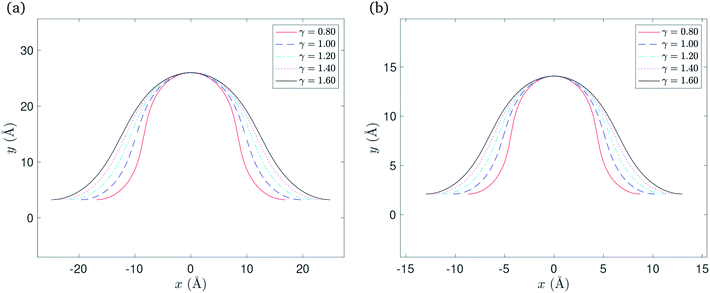 | ||
| Fig. 3 Rippled graphene sheet located on: (a) Cu(111) substrate and (b) Ni(111) substrate, for various bending rigidity γ, in the transitional case. | ||
Again using the substitution of θ = 2ϕ − ψ we deduce that
 . Hence, the total half arc length of the ripple is given by
 | (17) |
We may also calculate the elastic energy by integrating the square of the line curvature over the total length of C1 + C2, as follows
Hence, the total energy per unit length for this model is given by
 | (18) |
Numerical values for the x-component of the critical point x0 and the total half arc length of the ripple Lrip are presented in Table 2, for a range of values of the bending rigidity γ. The vdW interaction ξ takes a specific empirically derived value for each substrate as given in Table 1.
| γ (eV) | Cu(111) substrate | Ni(111) substrate | ||
|---|---|---|---|---|
| x0 (Å) | Lrip (Å) | x0 (Å) | Lrip (Å) | |
| 0.80 | 8.42 | 30.86 | 4.36 | 16.17 |
| 1.00 | 9.80 | 32.29 | 5.10 | 16.92 |
| 1.20 | 10.84 | 33.52 | 5.65 | 17.57 |
| 1.40 | 11.71 | 34.61 | 6.11 | 18.14 |
| 1.60 | 12.45 | 35.59 | 6.50 | 18.65 |
4 The substrate constrained case
We now consider the special case, shown in Fig. 2(b), by removing the assumed isoperimetric constraint on the total arc length of C to allow graphene to overhang the substrate. Therefore we discard the variation of x2 and substitute λ = 0, and into eqn (5) to obtain the functional that we wish to minimise, that is
 | (19) |
We note that this expression is identical to (6) with μ = 0, and so by the same reasoning as in Section 3 we obtain
![[small kappa, Greek, circumflex]](https://www.rsc.org/images/entities/i_char_e109.gif) = ±[sec = ±[sec![[thin space (1/6-em)]](https://www.rsc.org/images/entities/char_2009.gif) ψ ψ![[thin space (1/6-em)]](https://www.rsc.org/images/entities/char_2009.gif) cos(ψ + θ)]1/2. cos(ψ + θ)]1/2. |
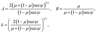
Consequently, we redefine some of our parameters so that now A = 2(sec![[thin space (1/6-em)]](https://www.rsc.org/images/entities/char_2009.gif) ψ)−1/2, B = 0, and
ψ)−1/2, B = 0, and  . Again the line curvature
 ![[small kappa, Greek, circumflex]](https://www.rsc.org/images/entities/i_char_e109.gif) changes sign at ϕ0 = sin−1(1/k) = π/4 which corresponds to the point (X0, Y0) and has similar coordinates to that in (15a) and (15b). Taking the redefined parameters into account, these coordinates are
changes sign at ϕ0 = sin−1(1/k) = π/4 which corresponds to the point (X0, Y0) and has similar coordinates to that in (15a) and (15b). Taking the redefined parameters into account, these coordinates are
X0 = [sin![[thin space (1/6-em)]](https://www.rsc.org/images/entities/char_2009.gif) ψ ψ![[thin space (1/6-em)]](https://www.rsc.org/images/entities/i_char_2009.gif) g2(ψ/2) − cos g2(ψ/2) − cos![[thin space (1/6-em)]](https://www.rsc.org/images/entities/char_2009.gif) ψ ψ![[thin space (1/6-em)]](https://www.rsc.org/images/entities/i_char_2009.gif) g1(ψ/2)], g1(ψ/2)], |
Similarly, with the rotational symmetry of the solutions about the point (X0, Y0), and the variation of ϕ over [ψ/2, π/4], the curves C1 and C2 still can be written as
XC1/C2(ϕ) = X0 ± [cos![[thin space (1/6-em)]](https://www.rsc.org/images/entities/char_2009.gif) ψ ψ![[thin space (1/6-em)]](https://www.rsc.org/images/entities/i_char_2009.gif) g1(ϕ) − sin g1(ϕ) − sin![[thin space (1/6-em)]](https://www.rsc.org/images/entities/char_2009.gif) ψ ψ![[thin space (1/6-em)]](https://www.rsc.org/images/entities/i_char_2009.gif) g2(ϕ)], g2(ϕ)], |
YC1/C2(ϕ)=Y0 ± [sin![[thin space (1/6-em)]](https://www.rsc.org/images/entities/char_2009.gif) ψ ψ![[thin space (1/6-em)]](https://www.rsc.org/images/entities/i_char_2009.gif) g1(ϕ) + cos g1(ϕ) + cos![[thin space (1/6-em)]](https://www.rsc.org/images/entities/char_2009.gif) ψ ψ![[thin space (1/6-em)]](https://www.rsc.org/images/entities/i_char_2009.gif) g2(ϕ)]. g2(ϕ)]. |
Using the same derivation as in Section 3, the Y component of the critical point in this case may be rewritten as
As before, multiplying the solutions above by the scaling factor  recovers the dimensional solutions for the curves C1 and C2.
Numerical results
In this case we have only one parameter to determine, namely ψ, and using the boundary condition YC2(ψ/2) = δ, the value of ψ may be determined numerically. After determining ψ, the solution is fully determined and representative plots are shown in Fig. 4. We comment here that the gradient of the graph for γ = 0.8 in the neighbourhood of the critical point becomes infinite when the ripple amplitude h ≈ 8.0![[thin space (1/6-em)]](https://www.rsc.org/images/entities/i_char_2009.gif) δ for the Cu(111) substrate, and h ≈ 6.7
δ for the Cu(111) substrate, and h ≈ 6.7![[thin space (1/6-em)]](https://www.rsc.org/images/entities/i_char_2009.gif) δ for the Ni(111) substrate where δ takes a specific empirical value for each substrate as presented in Table 1. We note that by increasing the ripple height the graphene sheet starts to bend over itself which is the transition point from the rippled state to the wrinkled state. Also, higher bending rigidities require higher ripple amplitudes for the maximum gradient to approach infinity. However, we fix these values of h for each corresponding substrate in all plots to enable comparison between various values of the bending rigidity γ.
δ for the Ni(111) substrate where δ takes a specific empirical value for each substrate as presented in Table 1. We note that by increasing the ripple height the graphene sheet starts to bend over itself which is the transition point from the rippled state to the wrinkled state. Also, higher bending rigidities require higher ripple amplitudes for the maximum gradient to approach infinity. However, we fix these values of h for each corresponding substrate in all plots to enable comparison between various values of the bending rigidity γ.
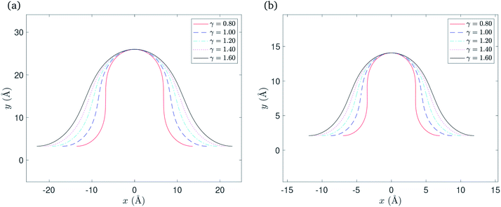 | ||
| Fig. 4 Rippled graphene sheet located on: (a) Cu(111) substrate and (b) Ni(111) substrate, for various bending rigidity γ, in the substrate constrained case. | ||
The total half arc length of the ripple Lrip and the total energy Etot for this case can be calculated from eqn (17) and (18), respectively, with the new parameters μ = 0 and ϕ0 = π/4. Thus, the total half arc length of the ripple is given by
Numerical values for the x-component of the critical point x0 and the total half arc length of the ripple are shown in Table 3, for a range of values for the bending rigidity γ. Again the vdW interaction strength ξ takes a specific empirically derived value for each substrate as given in Table 1.
| γ (eV) | Cu(111) substrate | Ni(111) substrate | ||
|---|---|---|---|---|
| x0 (Å) | Lrip (Å) | x0 (Å) | Lrip (Å) | |
| 0.80 | 6.79 | 29.81 | 3.49 | 15.63 |
| 1.00 | 8.44 | 31.13 | 4.37 | 16.32 |
| 1.20 | 9.65 | 32.34 | 5.02 | 16.95 |
| 1.40 | 10.63 | 33.43 | 5.53 | 17.52 |
| 1.60 | 11.45 | 34.44 | 5.97 | 18.04 |
5 The graphene constrained case
In this case, as shown in Fig. 2(c), in addition to the assumed isoperimetric constraint on the total arc length of C, we take into account the variations of x2, and assume it varies proportionally with x1, that isFollowing the nondimensionalisation described in Section 3, the total energy per unit length for this case is
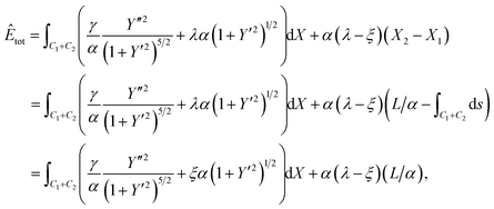 | (20) |
 . Further, the aim is to determine the shape of Y = Y(X) which minimises Êtot, and here λ has no impact on the solution, so we choose λ = ξ to simplify the calculation. The final form of the functional to be minimised is
 | (21) |
![[small kappa, Greek, circumflex]](https://www.rsc.org/images/entities/i_char_e109.gif) = ±[1 − β = ±[1 − β![[thin space (1/6-em)]](https://www.rsc.org/images/entities/char_2009.gif) sin sin![[thin space (1/6-em)]](https://www.rsc.org/images/entities/char_2009.gif) θ]1/2. θ]1/2.
| (22) |
Similarly, by comparing (22) with the equivalent expression for the transitional case (11), we note that in (22) ψ = π/2 and β acts in place of the term  as μ approaches 1. Therefore, we redefine the parameters A, B, and k in (14a) and (14b) as
The critical point (X0, Y0) represents the point of the rotational symmetry which again corresponds to ϕ0 = sin−1(1/k), and the coordinates of this point are given by
Similarly, the solutions on the curves C1 and C2 where ϕ ∈ [ϕ0, π/4] are
| XC1/C2(ϕ) = X0 ∓ g2(ϕ), and YC1/C2(ϕ) = Y0 ± g1(ϕ). |
Now, we use the boundary condition YC2(π/4) = δ/α to rewrite the Y component of the critical point as
The dimensional solutions for the curves C1 and C2 may be obtained by scaling these solution by  .
.
Numerical results
Here again we are left with only one parameter to determine, namely β, and using the boundary condition YC2(π/4) = δ, the value of β may be determined numerically. After finding β, the solution is fully determined and representative plots are shown in Fig. 5. The total half arc length of the ripple Lrip for this case can be evaluated from (17) with ψ = π/2 and to give
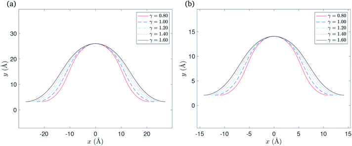 | ||
| Fig. 5 Rippled graphene sheet located on: (a) Cu(111) substrate and (b) Ni(111) substrate, for various bending rigidity γ, in the graphene constrained case. | ||
Similarly, the total energy per unit length Etot for this case is obtained from (18), which yields
Numerical values for the x-component of the critical point x0 and the total half arc length of the ripple Lrip are presented in Table 4 for a range of values of the bending rigidity γ. As before, the vdW interaction ξ takes a specific empirically derived value for each substrate as given in Table 1.
| γ (eV) | Cu(111) substrate | Ni(111) substrate | ||
|---|---|---|---|---|
| x0 (Å) | Lrip (Å) | x0 (Å) | Lrip (Å) | |
| 0.80 | 10.47 | 32.76 | 5.47 | 17.18 |
| 1.00 | 11.43 | 34.00 | 5.97 | 17.83 |
| 1.20 | 12.24 | 35.11 | 6.39 | 18.41 |
| 1.40 | 12.95 | 36.11 | 6.77 | 18.93 |
| 1.60 | 13.59 | 37.02 | 7.10 | 19.41 |
6 Results
For the purpose of comparison, we assume a fixed half length L = 700 Å for the rippled graphene sheet on a flat substrate. The goal is to obtain a relationship between the variation of the substrate length and the total energy per unit length for the rippled graphene. The substrate half length Lsub is divided into three regimes that correspond to the point x2, where the graphene edge ends, which can be calculated by x2 = x1 + L − Lrip. Here we comment that x2s < x2g where x2s and x2g correspond to the substrate constrained case and the graphene constrained case, respectively.The substrate constrained case was formulated to describe the regime where Lsub < x2s, provided that as Lsub gets closer to x2s the total energy per unit length Etot decreases due to the vdW interactions that occur when Lsub increases. The graphene constrained case can be adapted to address the regime when Lsub > x2g, and here the total energy per unit length Etot remains constant since there are no more interactions that are involved for this section. Finally, the transitional case is used to evaluate the total energy per unit length Etot when Lsub ≈ x2. Multiple values for x2t were chosen from the interval [x2s, x2g] to fill the gap between the substrate constrained case and the graphene constrained case where x2t denotes the location of the graphene edge in the transitional case. Fig. 6 illustrates the relationship between varying the substrate length and total energy per unit length included the three cases discussed above.
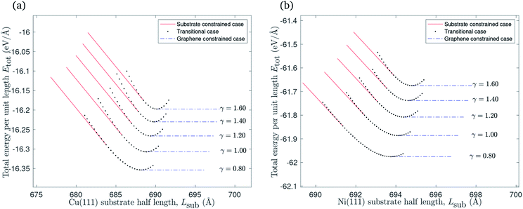 | ||
| Fig. 6 The relationship between varying the substrate length of: (a) Cu(111) substrate, (b) Ni(111) substrate and the total energy per unit length. | ||
A graphene sheet of half length L = 700 Å will remain flat when it is placed on a flat substrate of the same half length. The substrate constrained case can be adapted to investigate the impact of reducing the substrate length on the graphene sheet. Fig. 7 shows that ripples form in this scenario, and that there is an increase in the ripple amplitude as the substrate length decreases. Graphene of lower bending rigidity reaches the ripple height for which the gradient of the ripple becomes infinite at a relatively longer substrate than graphene with a higher bending rigidity. The substrate length at which the ripple gradient becomes infinite corresponds to the left end-point of each curve in Fig. 7.
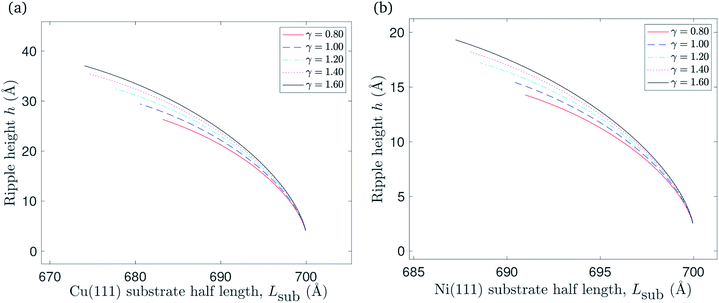 | ||
| Fig. 7 The relationship between reducing the substrate length of: (a) Cu(111) substrate, (b) Ni(111) substrate and the ripple amplitude. | ||
The impact of reducing the substrate length on the total energy per unit length is presented in Fig. 8. The total energy per unit length of the flat graphene sheet is approximated at −17.2 eV Å−1 when it is placed on copper, and at −63.5 eV Å−1 in the case of a nickel substrate. It increases when the substrate length decreases, as expected due to reduced vdW interactions between the graphene sheet and the substrate, as well as elastic energy stored in the ripple. The points marked with circles represent (Lsub0, Etot(Lsub0)) where Lsub0 denotes the substrate length when the gradient of the total energy per unit length curve approaches −ξ.
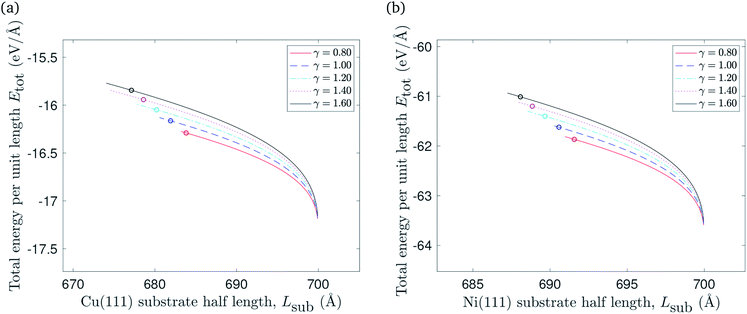 | ||
| Fig. 8 The relationship between reducing the substrate length of: (a) Cu(111) substrate, (b) Ni(111) substrate and the total energy per unit length. | ||
Starting from a flat graphene sheet laying on a shrinking substrate, the system might form a ripple or remain flat and beginning to overhang the substrate. The ripple formation pathway would follow the transitional case and the flat pathway would follow the substrate constrained case. In an ideal setting, ripples would not form because the energy require to follow the first pathway exceeds the energy lost in following the second. However, we comment that many experimental situations include confounding effects such as impurities and defects in the graphene structure which are not accounted for in this work.
Recently, morphologies of graphene wrinkles on copper substrate were experimentally investigated by Wang et al.28 They observed unexpected profiles of wrinkles with widths in the range of tens of nanometres, and heights in the range of a few nanometres. Their theoretical methods and MD simulations agree that the maximum width of wrinkles is less than 2.7 nm which is largely smaller than those experimentally observed. As they reported, the presence of interlayer molecules between the graphene and the copper substrate is the main mechanism that enlarges both width and height of graphene wrinkle. Since we don't take into account interlayer molecules, our model is comparable with their MD simulations without interlayer molecules. Their MD simulation model, as reprinted in Fig. 9(a) and (b), is a stack of two rectangular materials, upper cyan graphene and lower red copper which is best modelled by the transitional case in our model. Therefore, the conformations of rippled (or wrinkled) graphene on a copper substrate, obtained by the transitional case, with bending rigidity γ = 1.20 eV and different heights are adopted to compare with the results of MD simulations of graphene wrinkles obtained by Wang et al.,28 as shown in Fig. 9(c). Despite the fact that the present model uses the value of 2.481 eV nm−2 for the vdW energy of graphene–Cu(111) interactions per unit area, but their model used the value of 4.494 eV nm−2, both results are in excellent agreement in predicting the profiles of graphene ripples (or wrinkles).
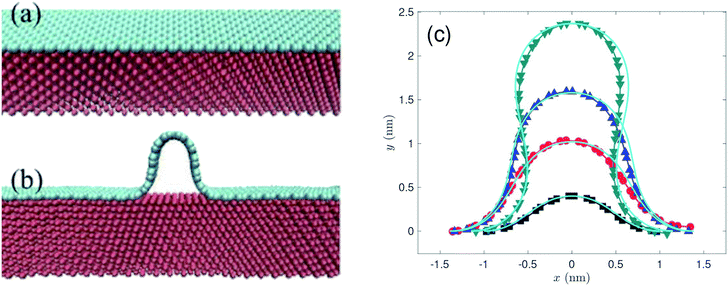 | ||
| Fig. 9 MD simulation models and results of graphene wrinkles reprinted (or adapted) from ref. 28, licensed under a http://creativecommons.org/licenses/by/4.0/. (a and b) The MD simulation model, performed by Wang et al.,28 is presented here in order to adopt the appropriate case among those developed in this model for comparison purposes. (c) The profiles of graphene ripples or wrinkles obtained by present model (cyan lines) superimposed upon the results of MD simulation.28 | ||
7 Summary
In this paper, we develop a model for a rippled graphene sheet that is located on a flat metal substrate. The assumed translational symmetry along the ripple reduces our problem to two dimensions, and the reflective symmetry about the y-axis allows us to consider only solutions in the upper right quadrant. We employ variational calculus to minimise the elastic energy arising from the curvature squared and maximising the vdW interaction energy between the flat section of the graphene and the metal substrate.We account for the length of the substrate by considering three different cases. The first addresses the case when the edges of the rippled graphene sheet and the substrate coincide. The second case is when the edge of the graphene sheet overhangs the substrate edge, and the last case applies to a rippled graphene sheet for which the edge of the sheet does not extend to the substrate edge. We assume a fixed half length of the graphene sheet, and consider all three cases to obtain a continuous relationship between the total energy per unit length of the graphene and the length of the substrate as shown in Fig. 6. The substrate constrained case is used to illustrate the effect of reducing the substrate length on the ripple height and the total energy of the graphene as shown in Fig. 7 and 8. Using the transitional case, our model is shown to agree with the results of earlier MD simulations of graphene ripples (or wrinkles) on a Cu(111) substrate.
Future research may address the phenomenon of ripple formation when the substrate shrinks by taking into account additional physical effects. For instance the model maybe extended to account for the change in the vdW interaction strength as the substrate length and density change. This will introduce ξ as a function of x and lead to an explicit dependence on x in the integrand part of (6), which would undoubtedly complicate the corresponding Euler–Lagrange equation.
Conflicts of interest
There are no conflicts to declare.Acknowledgements
Jabr Aljedani would like to acknowledge the financial support provided by King Abdulaziz University.References
- P. Blake, E. Hill, A. Castro Neto, K. Novoselov, D. Jiang, R. Yang, T. Booth and A. Geim, Appl. Phys. Lett., 2007, 91, 063124 CrossRef.
- J. S. Bunch, A. M. Van Der Zande, S. S. Verbridge, I. W. Frank, D. M. Tanenbaum, J. M. Parpia, H. G. Craighead and P. L. McEuen, Science, 2007, 315, 490–493 CrossRef CAS PubMed.
- C. Lee, X. Wei, J. W. Kysar and J. Hone, Science, 2008, 321, 385–388 CrossRef CAS PubMed.
- X. Li, W. Cai, J. An, S. Kim, J. Nah, D. Yang, R. Piner, A. Velamakanni, I. Jung and E. Tutuc, et al., Science, 2009, 324, 1312–1314 CrossRef CAS PubMed.
- J. C. Meyer, A. K. Geim, M. I. Katsnelson, K. S. Novoselov, T. J. Booth and S. Roth, Nature, 2007, 446, 60 CrossRef CAS PubMed.
- A. C. Neto, F. Guinea, N. M. Peres, K. S. Novoselov and A. K. Geim, Rev. Mod. Phys., 2009, 81, 109 CrossRef.
- Y. Zhu, S. Murali, W. Cai, X. Li, J. W. Suk, J. R. Potts and R. S. Ruoff, Adv. Mater., 2010, 22, 3906–3924 CrossRef CAS PubMed.
- K.-T. Lam, C. Lee and G. Liang, Appl. Phys. Lett., 2009, 95, 143107 CrossRef.
- M. Poetschke, C. Rocha, L. F. Torres, S. Roche and G. Cuniberti, Phys. Rev. B: Condens. Matter Mater. Phys., 2010, 81, 193404 CrossRef.
- Y. Wei, B. Wang, J. Wu, R. Yang and M. L. Dunn, Nano Lett., 2013, 13, 26–30 CrossRef CAS PubMed.
- S. P. Koenig, L. Wang, J. Pellegrino and J. S. Bunch, Nat. Nanotechnol., 2012, 7, 728 CrossRef CAS PubMed.
- K. Kostarelos and K. S. Novoselov, Nat. Nanotechnol., 2014, 9, 744 CrossRef CAS PubMed.
- B. Yu, H. Li, J. White, S. Donne, J. Yi, S. Xi, Y. Fu, G. Henkelman, H. Yu and Z. Chen, et al., Adv. Funct. Mater., 2020, 30, 1905665 CrossRef CAS.
- S. Wang, B. Yang, H. Chen and E. Ruckenstein, Energy Storage Materials, 2019, 16, 619–624 CrossRef.
- S. Wang, B. Yang, H. Chen and E. Ruckenstein, J. Mater. Chem. A, 2018, 6, 6815–6821 RSC.
- F. Schedin, A. Geim, S. Morozov, E. Hill, P. Blake, M. Katsnelson and K. Novoselov, Nat. Mater., 2007, 6, 652 CrossRef CAS PubMed.
- C. H. Lui, L. Liu, K. F. Mak, G. W. Flynn and T. F. Heinz, Nature, 2009, 462, 339 CrossRef CAS PubMed.
- W. Bao, F. Miao, Z. Chen, H. Zhang, W. Jang, C. Dames and C. N. Lau, Nat. Nanotechnol., 2009, 4, 562 CrossRef CAS PubMed.
- I. Pletikosić, M. Kralj, P. Pervan, R. Brako, J. Coraux, A. N'diaye, C. Busse and T. Michely, Phys. Rev. Lett., 2009, 102, 056808 CrossRef PubMed.
- G. Gui, J. Zhong and Z. Ma, J. Phys.: Conf. Ser., 2012, 402, 012004 CrossRef.
- A. Fasolino, J. Los and M. I. Katsnelson, Nat. Mater., 2007, 6, 858 CrossRef CAS PubMed.
- J. M. Carlsson, Nat. Mater., 2007, 6, 801 CrossRef CAS PubMed.
- B. J. Cox, D. Baowan, W. Bacsa and J. M. Hill, RSC Adv., 2015, 5, 57515–57520 RSC.
- T. Dyer, N. Thamwattana and B. Cox, J. Mol. Model., 2018, 24, 99 CrossRef PubMed.
- T. Olsen, J. Yan, J. J. Mortensen and K. S. Thygesen, Phys. Rev. Lett., 2011, 107, 156401 CrossRef PubMed.
- Z. Xu and M. J. Buehler, J. Phys.: Condens. Matter, 2010, 22, 485301 CrossRef PubMed.
- Y. Gamo, A. Nagashima, M. Wakabayashi, M. Terai and C. Oshima, Surf. Sci., 1997, 374, 61–64 CrossRef CAS.
- W. Wang, S. Yang and A. Wang, Sci. Rep., 2017, 7, 1–6 CrossRef PubMed.
| This journal is © The Royal Society of Chemistry 2020 |

