DOI:
10.1039/C9RA10952H
(Paper)
RSC Adv., 2020,
10, 6114-6120
Ag2O-decorated electrospun BiVO4 nanofibers with enhanced photocatalytic performance†
Received
27th December 2019
, Accepted 25th January 2020
First published on 7th February 2020
Abstract
Semiconductor photocatalysts are emerging as tools for pollutant degradation in industrial wastewater, air purification, antibacterial applications, etc. due to their use of visible light, which is abundant in sunlight. Here, we report a new type of p–n junction Ag2O/BiVO4 heterogeneous nanostructured photocatalyst with enhanced photocatalytic performance. P-type Ag2O nanoparticles were in situ reduced and assembled on the surface of electrospun BiVO4 nanofibers using ultraviolet (UV) irradiation; this process hindered the recombination of localized photogenerated electron–hole pairs, and hence resulted in the enhanced photocatalytic activity of the BiVO4/Ag2O nanocomposites. The photocatalytic activities of the obtained BiVO4 and BiVO4/Ag2O nanocomposites were assessed by measuring the degradation of rhodamine B (RhB) under visible light. The 10 wt% Ag2O/BiVO4 sample yielded the optimum degradation of RhB (98.47%), much higher than that yielded by pure BiVO4 nanofibers (64.67%). No obvious change in the XRD pattern of an Ag2O/BiVO4 sample occurred as a result of its use in the photocatalytic reaction, indicating its excellent stability. The high photocatalytic performance observed was attributed to the large surface-to-volume ratio of the essentially one-dimensional electrospun BiVO4 nanofibers and to the in situ growth of p-type Ag2O on the surface of the n-type BiVO4 nanofibers.
1. Introduction
Metal oxide semiconductor photocatalysts have been used to greatly alleviate such problems as water pollution and those involving the environment and energy issues by using visible light of the solar spectrum, in particular collecting it to generate charge carriers, and promoting charge separation and transfer.1–5 TiO2 is an excellent photocatalyst and is also strongly oxidizing, chemically stable, inexpensive and non-toxic, and has been widely studied.6,7 However, the band gap of TiO2 is approximately 3.2 eV, which leads to a rapid recombination of the photogenerated electron–hole pairs and absorption of only ultraviolet (UV) light (only about 4% of total sunlight), and hence TiO2 is not a suitable and effective photocatalyst for water purification.8,9 Recently, n-type bismuth vanadate (BiVO4) with a monoclinic scheelite-like structure has become considered as a promising class of photocatalysts owing to its narrower band gap of 2.4 eV compared to that of TiO2, resulting in an easy separation of photogenerated electrons from holes and excellent photocatalytic performance.10–14
The morphology, structure and specific surface area of BiVO4 materials obtained via traditional approaches, however, have not met the requirements for more efficient photocatalysis development.15,16 Nevertheless, by controlling the morphologies and structures of BiVO4 and BiVO4 materials modified with noble metals and its oxides, further improvements of the photocatalytic performances of BiVO4 materials can be realized.17 With regards to the control of morphology, in comparison with decahedral BiVO4 structures and BiVO4 nanorods, nanobelts, nanotubes and nanospheres, one-dimensional (1D) BiVO4 nanofibers (NFs) display many advantages: (1) large surface-to-volume ratios, which could prolong the photocarrier lifetime; (2) very large aspect ratios, forming a unique charge transfer path along the 1D direction; and (3) abundant surface active sites, which could provide many active sites for subsequent surface modifications of the BiVO4.18–24 As for modifications with noble metals, doping n-type noble metals oxides onto the surfaces of p-type bismuth vanadate semiconductors is a feasible way to construct p–n heterojunctions with enhanced photocatalytic performances.25–28
Based on these considerations, we prepared p–n junction Ag2O/BiVO4 heterogeneous structures by in situ reducing Ag2O nanoparticles on the surfaces of 1D electrospun BiVO4 NFs. As-obtained 10 wt% Ag2O/BiVO4 NFs showed enhanced photocatalytic activity towards degradation of rhodamine B (RhB) pollutants under visible light (photocatalytic efficiency: 98.47% within 100 minutes). Moreover, after three photodegradation cycles, the degradation efficiency was still about 90%, indicating its outstanding cycle stability. Theoretical studies indicated this enhanced photocatalysis to be due to the 1D nature of the electrospun BiVO4 NFs and due to the construction of p–n junction Ag2O/BiVO4 heterogeneous structures.
2. Experimental
2.1. Synthesis of BiVO4 NFs
BiVO4 NFs were synthesized by employing the electrospinning method. In a typical process, 1.21 g of Bi(NO3)3·5H2O and 0.662 g of vanadyl acetylacetonate (VO(acac)2) were dissolved in 5 mL of N,N-dimethylformamide (DMF) under magnetic stirring for 2 h. Afterwards, a mass of 0.7 g of polyvinyl pyrrolidone (PVP) was added to the above mixture under magnetic stirring for 8 h to form a bottle green precursor spinning solution. This solution was drawn up into a 10 mL plastic syringe via a stainless steel needle with an inner diameter of 0.5 mm, and then a voltage of 18 kV was applied over a distance of 15 cm between the needle tip and an aluminium foil collector. After carrying out the collection process for 1 h, the generated precursor was dried in a vacuum oven at 60 °C for 12 h. Finally, the dried BiVO4 precursor was calcinated in a muffle furnace set at various temperatures (400 °C, 500 °C, 600 °C) each for 1 h and with a constant heating rate of 1 °C min−1 between these levels.29
2.2. In situ growth of Ag2O nanoparticles on the BiVO4 NFs
Ag2O nanoparticles were in situ reduced and assembled on the surfaces of BiVO4 NFs by applying ultraviolet (UV) irradiation. First, in each of series of samples, a mass of 0.1 g of as-prepared BiVO4 calcinated at 500 °C was dispersed in 40 mL of deionized water. To these samples were added AgNO3 at different mass fractions, of 3%, 5%, 10% and 15%, respectively, to form suspensions under magnetic stirring. The suspensions were stirred under UV light illumination for 5 h. The final powders were washed with deionized water several times, and then dried at 60 °C in the air for 12 h.
2.3. Characterizations
The morphologies, structures and crystalline forms of BiVO4 NFs and Ag2O-doped BiVO4 NFs were investigated by using a scanning electron microscope (SEM, MAGELLIAN-400), transmission electron microscope (TEM, JEM-2200FS), and X-ray powder diffractometer system (XRD, Rigaku D/max-2550), respectively. The change in the mass of a BiVO4 precursor as a function of temperature and time was assessed by acquiring thermogravimetric analysis and differential scanning calorimetry (TGA/DSC) curves in the isothermal mode using a TA SDT Q600 thermogravimetry analyzer. Raman spectra were acquired by using a Raman spectroscopy apparatus (Spex 1403) with a 514 nm-wavelength laser to identify the molecular structures of the samples. X-ray photoelectron spectroscopy (XPS) data were measured with an ESCALAB 250 electron spectrometer to characterize the surface chemical states of the samples. An absorption spectrum was obtained with a UV-Vis spectrophotometer (UV-2450), using BaSO4 as a reference.
3. Results and discussion
Fig. 1a and S1a† show the SEM images acquired of the BiVO4 precursor. Inspection of the images showed a very smooth surface of the BiVO4 precursor, attributed to it containing the high-molecular-weight PVP template. The BiVO4 precursor formed fibers with an average diameter of 500 nm. Fig. S1b–d† display the SEM images acquired of the BiVO4 precursors calcinated at 400 °C, 500 °C and 600 °C. Inspection of these images showed the roughness and variation in diameter of the BiVO4 NFs after calcination, features attributed to the volatilization of the DMF and PVP. When the temperature reached 500 °C, many pores were observed evenly distributed on the surfaces of the BiVO4 NFs, and the average NF diameter decreased to about 250 nm. When the annealing temperature was further increased, the NFs gradually broke apart, so we chose the BiVO4 NFs annealed at 500 °C as the template to grow Ag2O particles. The XRD of the BiVO4 NFs (Fig. S2†) calcinated at the three temperatures also demonstrated that the crystallinity of the NFs annealed at 500 °C was the best. The acquired SEM images of the Ag2O/BiVO4 NFs are shown in Fig. 1b and c. Ag2O particles were observed to be uniformly distributed on the BiVO4 NFs. Fig. 1d shows the acquired SEM image of a single Ag2O/BiVO4 NF and images of its corresponding elemental mapping. The dot mapping images of Bi, V, O, and Ag followed closely the backbone of the NF, suggesting the successful synthesis of the Ag2O/BiVO4 NFs. A closer TEM observation of an Ag2O/BiVO4 NF (Fig. 1e) indicated that the equally distributed Ag2O particles did not change the fiber structure of BiVO4. Fig. 1f shows a high-resolution TEM (HRTEM) image of a marginal area of the Ag2O/BiVO4 NF shown in Fig. 1e, and indicated the monoclinic structure of the as-synthesized BiVO4 NFs and Ag2O particles. The lattice constant measured from the scheelite-like structure of the BiVO4 NF was 0.308 nm, in agreement with the (112) planes of the BiVO4 phase.13 A lattice spacing value of 0.236 nm was assigned to the (200) planes of the Ag2O phase. The selected area electron diffraction pattern (Fig. 1g) acquired from an Ag2O/BiVO4 NF showed the same good crystallinity and nanocomposite structure. The energy dispersive X-ray (EDX) spectrum acquired of an Ag2O/BiVO4 NF is shown in Fig. 1h, and revealed that the NF was composed of Bi, V, O and Ag elements. Fig. 1i shows thermogravimetric analysis and differential scanning calorimetry (TGA/DSC) curves indicative of the synthesis of porous BiVO4 NFs.30 Analysis of the acquired X-ray diffraction (XRD) pattern (Fig. 1j) further confirmed that the as-synthesized NFs were monoclinic scheelite-like-structured BiVO4 NFs (JCPDS card no. 75-2480).17,31,32 None of the XRD patterns of the samples showed any characteristic diffraction peak corresponding to Ag2O particles, attributed to the small quantities of Ag2O in the as-synthesized samples.
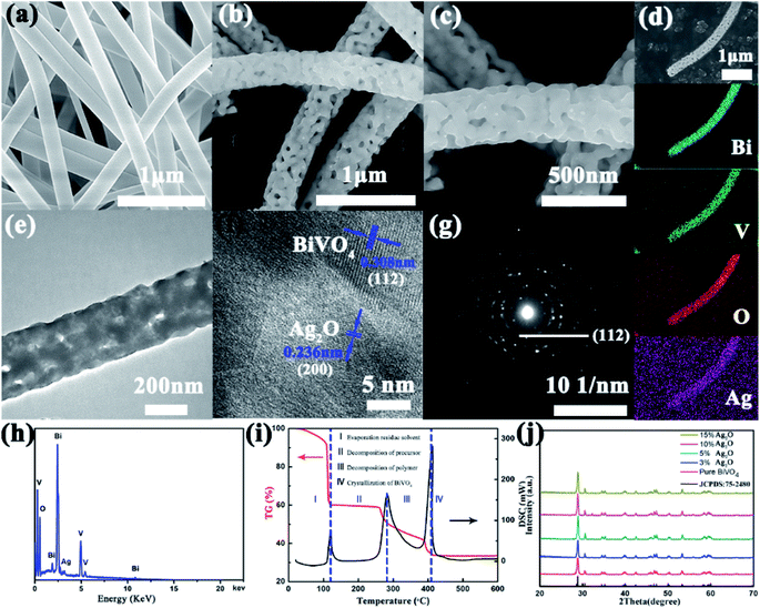 |
| | Fig. 1 (a) An SEM image of an obtained BiVO4 precursor. (b and c) Typical SEM images of Ag2O-doped BiVO4 NFs. (d) An SEM image of a single Ag2O/BiVO4 NF with the corresponding Bi, V, O and Ag elemental mapping images. (e) A TEM image and (f) high-resolution TEM (HRTEM) image of an Ag2O/BiVO4 NF. (g) Selected area electron diffraction (SEAD) pattern and (h) EDAX data of the Ag2O/BiVO4 NF taken from the area marked in (b). (i) TGA/DSC curves of Ag2O/BiVO4 NFs (TGA curve: red; DSC curve: black; heating range: 30–600 °C with a rate of 5 °C min−1). (j) XRD patterns of pure BiVO4 and Ag2O/BiVO4 composites. | |
XPS data were collected to monitor the elemental composition of the nanocomposites and valence states of the elements, as shown in Fig. 2. Fig. 2a shows the survey XPS spectrum of Ag2O/BiVO4 NFs. Analysis of this spectrum indicated that the samples consisted of Bi, V, O and Ag elements, in agreement with the results of mapping images and the EDX spectrum. The acquired high-resolution XPS spectrum of the Ag2O/BiVO4 NFs in the Bi 4f, V 2p, O 1s and Ag 3d regions are shown in Fig. 2b–e, respectively. In the Bi 4f region (Fig. 2b), the two peaks located at 159.35 eV and 164.67 eV can be attributed to the binding energies of Bi 4f5/2 and Bi 4f7/2 with a spin–orbit splitting energy of 5.32 eV, demonstrating that element Bi was present in the form Bi3+. Fig. 2c displays the V 2p region of the spectrum, which can be deconvoluted into two sets of peaks centered at 517.3 eV and 524.9 eV, corresponding to V 2p3/2 and V 2p5/2 with a spin–orbit splitting energy of 7.6 eV.33,34 In comparison with XPS spectra of pure BiVO4 NFs (Fig. S3†), no obvious change was found in the spin–orbit splitting energy values of the Bi and V elements, but for the O element, a new peak at 534.7 eV and attributed to Ag2O appeared in the O 1s region of the XPS spectrum of the hybrid composites. To further determine the valence state of the elements Ag, the high-resolution XPS spectrum in its Ag 3d region (Fig. 2e) was further analyzed. Two observed peaks at 374.9 eV and 368.9 eV can be ascribed to the binding energies of Ag 3d3/2 and Ag 3d5/2 with a spin–orbit splitting energy of 6 eV, consistent with the chemical state of Ag2O. All above analysis results taken together showed that the Ag2O nanoparticles became tightly bound to the surfaces of the BiVO4 NFs, beneficial for the photocatalytic performance.
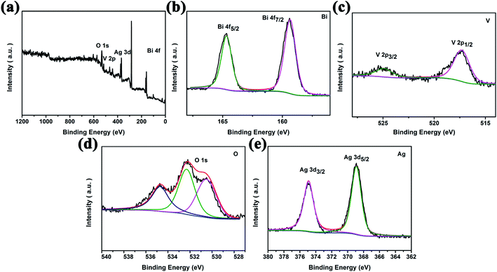 |
| | Fig. 2 High-resolution XPS spectra of 10 wt% Ag2O/BiVO4 samples: (a) the survey spectrum and (b) Bi 4f, (c) V 2p, (d) O 1s, and (e) Ag 3d spectra. | |
After characterizing the elementary morphologies and structures of the Ag2O/BiVO4 NFs, photocatalytic performance studies were systematically conducted. First, UV-Vis diffuse absorption spectra (UV-Vis DRS) of as-prepared samples were acquired, as shown in Fig. 3a and S4,† to investigate their photo-absorption properties. According to the UV-Vis DRS of pure BiVO4 shown in Fig. S4,† the sample showed relatively strong absorption of light at wavelengths of 300 to 450 nm, but weakening absorption as the wavelength of the light was increased above 450 nm, indicating that BiVO4 by itself can only be excited by UV light. After BiVO4 was decorated with Ag2O nanoparticles, the UV-Vis DRS of the resulting Ag2O/BiVO4 NFs (Fig. 3a) showed a significant red-shift of the absorption compared to that of the pure BiVO4 NFs. All the composites with different mass ratios exhibited enhanced absorption of visible light, which can be attributed to the heterojunction formed between Ag2O and BiVO4 NFs having changed the optical properties of the photocatalyst, and suggesting that it would display outstanding activity in the visible light region. The p–n heterojunction effectively decreased the coupling of the photogenerated electron–hole pairs, thus resulting in the enhanced visible light absorption. The corresponding photocurrent density was measured in a three-electrode system in a 0.5 M K2SO4 aqueous electrolyte with a Pt counter electrode, an Ag/AgCl reference electrode, and as-prepared Ag2O/BiVO4 NFs serving as the working electrode. The photocurrent–time curves of Ag2O/BiVO4 NFs with various mass ratios are displayed in Fig. 3b. These curves showed that the photocurrent density of the 10% Ag2O/BiVO4 NFs was greater than that of the samples with other proportions of the components and with the same illumination time. This result can be attributed to n-type Ag2O in moderate amounts being able to hinder photonic electron–hole pairs from recombining and excess Ag2O nanoparticles in the nanocomposites forming a load center of carriers and hence impeding the separation of photogenerated electrons and holes.
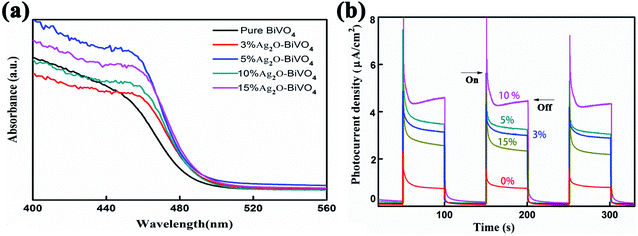 |
| | Fig. 3 (a) UV-Vis diffuse absorption spectra of pure BiVO4 photocatalysts and Ag2O/BiVO4 samples with various mass ratios of the components. (b) The corresponding photocurrent density curves. | |
Fig. 4a shows the degradation of an RhB pollutant under visible light irradiation using pure BiVO4 NFs as well as Ag2O/BiVO4 samples with various mass ratios. No obvious degradation was observed in the absence of any photocatalyst. When any of the as-prepared Ag2O/BiVO4 photocatalysts were added, the RhB pollutant almost fully degraded after irradiation of 100 min. In the presence of pure BiVO4, 3%, 5%, 10%, and 15% Ag2O/BiVO4, 64.67%, 90.2%, 96.65%, 98.47%, and 96.65%, respectively, of the initial amount of RhB degraded within the 100 minutes. The 10% Ag2O/BiVO4 NFs exhibited the highest activity, with the degradation rate increased by 32.8% compared to that of the pure BiVO4 NFs. The kinetic curves of RhB degradation are displayed in Fig. 4b, and indicated that the degradation can be approximated as a pseudo-first-order process following the linear transform ln(C0/Ct) = kt, where k is the degradation rate constant.35,36 All of the Ag2O/BiVO4 composites exhibited higher photocatalytic activities than did the bare BiVO4. The degradation rate constant (k) of the Ag2O/BiVO4 with a 10% mass ratio was calculated to be 0.03908 min−1, a value quite remarkably about 1.62, 1.23 and 1.96 times those for the Ag2O/BiVO4 samples with 3%, 5% and 15% Ag2O loads, respectively. The above two results indicated that decoration of Ag2O nanoparticles on the surface of BiVO4 NFs did indeed improve the photocatalytic properties, and indicated that using the appropriate mass ratio of Ag2O in the as-prepared composites was crucial to the synergistic effects during the photocatalytic reaction. Therefore, we chose 10% of Ag2O/BiVO4 for further study. To investigate the effect of photocatalyst dosage on the photocatalytic performances, photocatalytic reductions of RhB using various masses of 10% Ag2O/BiVO4 photocatalysts under visible-light irradiation were performed, as shown in Fig. 4c. Notably, a mass of 5 mg of the Ag2O/BiVO4 photocatalyst degraded nearly all of the RhB pollutant. In contrast, when using more of the photocatalyst, the photocatalytic performance was poorer. This result was attributed to excessive photocatalyst in the RhB solution increasing the turbidity of the solution, a feature adverse to the penetration of visible light. The photocatalytic reductions of various concentrations of RhB using 5 mg of the Ag2O/BiVO4 (10%) are shown in Fig. 4d. When the initial concentration of the RhB solution was 20 mg L−1, the degradation efficiency of the Ag2O/BiVO4 sample was about 10% lower than that for 10 mg L−1. This result may have been due to the more concentrated solutions having been darker and hence showing worse transmittance of light, with fewer photons arriving at the surface of photocatalyst and leading to the decrease of the degradation efficiency. In addition, with the increase of the initial concentration of the solution, the surface of the photocatalyst would have produced more reactants, decreasing the density of available active sites on the surface of the photocatalyst, and hence affecting the utilization of visible light and causing the decline of the degradation efficiency.37
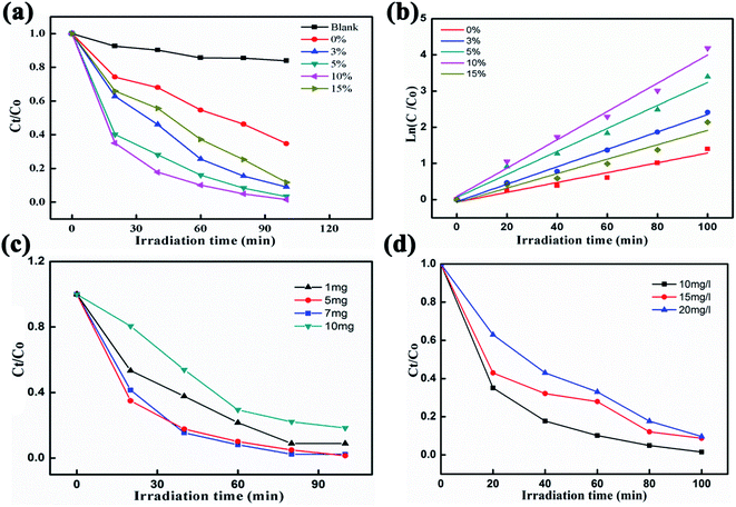 |
| | Fig. 4 (a) Photocatalytic reductions of RhB using pure BiVO4 photocatalysts and Ag2O/BiVO4 samples with various mass ratios. (b) The linear relationships of ln(Ct/C0) versus time for the degradation of RhB. (c) Photocatalytic reductions of RhB in the presence of various masses of 10 wt% Ag2O/BiVO4 photocatalyst under visible-light irradiation. (d) Photocatalytic reductions of various concentrations of RhB using 10 wt% Ag2O/BiVO4. | |
To assess the practical applicability of the photocatalyst, the cycling stability of the 10% Ag2O/BiVO4 hybrid composite was also assessed, as shown in Fig. 5a. Even after three photocatalytic reduction processes, 90% of initial value was observed for the Ag2O/BiVO4 photocatalyst, demonstrating its outstanding cycle performances. Fig. 5b displays the acquired XRD spectra of the Ag2O/BiVO4 photocatalyst before and after the photocatalytic reaction. We found that the phase structure of Ag2O/BiVO4 after the photodegradation was nearly the same as that before the photodegradation, showing the excellent stability and reusability of the photocatalyst.
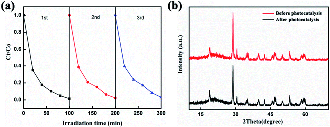 |
| | Fig. 5 (a) Three cycles of photocatalytic reductions of RhB using 10 wt% Ag2O/BiVO4 as the photocatalyst. (b) XRD patterns of Ag2O/BiVO4 before and after photocatalysis. | |
In order to arrive at a best possible understanding of the mechanism of the photocatalysis of a heterostructured photocatalyst system, we produced a schematic of the energy diagram and charge separation in the Ag2O/BiVO4 NFs under visible light irradiation (Fig. 6). BiVO4 and Ag2O are n-type and p-type semiconductors, respectively, and the combination of them can form a p–n heterostructure semiconductor. Under visible-light irradiation, Ag2O can be excited because of its relatively narrow bandgap of 1.3 eV, and the resulting photo-induced electrons would be expected to be able to transfer from the conduction band (CB) of Ag2O to that of BiVO4 NFs. But considering the higher CB potential of BiVO4 NFs than those of O2/·O2− (−0.33 eV) and O2/H2O2 (0.695 eV), the electrons on the CB of BiVO4 NFs cannot reduce O2 to generate ·O2−, H2O2, and ·OH, which are strong oxidizing groups that, if present, can break down the target RhB into H2O, CO2, and so on, so as to assist in reaching the goal of improved photocatalytic performance.34,38–40
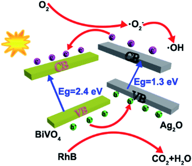 |
| | Fig. 6 A schematic illustration of the mechanism by which the p–n junctions of the Ag2O/BiVO4 samples are formed. | |
The possible reactions for the degradation of RhB are as follows.
| Ag2O − BiVO4 + hv → Ag2O − BiVO4 (eCB−···hVB+) |
| Ag2O (eCB−) + BiVO4 → Ag2O + BiVO4 (eCB−) |
| RhB + Ag2O (hVB+) → degradation products |
Here, e
CB− and h
VB+ denote an electron in the CB and hole in the VB, respectively.
4. Conclusions
In conclusion, a novel p–n junction Ag2O/BiVO4 heterogeneous photocatalyst has been successfully synthesized by reducing Ag2O nanoparticles in situ on the surfaces of 1D electrospun BiVO4 NFs. The obtained Ag2O/BiVO4 NFs with 10% mass ratio of Ag2O showed 98.47% photocatalytic efficiency within 100 minutes of exposure to visible light, and showed robust cycling stability, with a degradation efficiency of 90% after three cycles. The enhanced photocatalytic performance of the Ag2O/BiVO4 heterogeneous photocatalyst can be attributed to the special 1D structure of the hybrid composites—and to the synergistic effect of Ag2O nanoparticles and BiVO4 NFs forming heterogeneous p–n junction structures and hence impeding the recombination of photogenerated electron–hole pairs.
Conflicts of interest
There are no conflicts to declare.
Acknowledgements
The authors sincerely acknowledge financial support from the China Postdoctoral Science Foundation (2014M550392), and a Special Financial Grant from the China Postdoctoral Science Foundation (2017T100799).
References
- P. Dumrongrojthanath, T. Thongtem, A. Phuruangrat and S. Thongtem, Superlattices Microstruct., 2013, 64, 196–203 CrossRef CAS.
- R. V. Gonçalves, P. Migowski, H. Wender, D. Eberhardt, D. E. Weibel, F. C. Sonaglio, M. J. M. Zapata, J. Dupont, A. F. Feil and S. R. Teixeira, J. Phys. Chem. C, 2012, 116, 14022–14030 CrossRef.
- G. Longo, F. Fresno, S. Gross and U. L. Stangar, Environ. Sci. Pollut. Res. Int., 2014, 21, 11189–11197 CrossRef CAS PubMed.
- K. H. Kim and S. K. Ihm, J. Hazard. Mater., 2011, 186, 16–34 CrossRef CAS.
- W. Dong, D. Wang, H. Wang, M. Li, F. Chen, F. Jia and H. Li, J. Colloid Interface Sci., 2019, 535, 444–457 CrossRef CAS PubMed.
- W. Zhou, W. Li, J. Q. Wang, Y. Qu, Y. Yang, Y. Xie, K. Zhang, L. Wang, H. Fu and D. Zhao, J. Am. Chem. Soc., 2014, 136, 9280–9283 CrossRef CAS PubMed.
- C.-J. Li, J.-N. Wang, B. Wang, J. R. Gong and Z. Lin, Mater. Res. Bull., 2012, 47, 333–337 CrossRef CAS.
- W. Wang, L. Jing, Y. Qu, Y. Luan, H. Fu and Y. Xiao, J. Hazard. Mater., 2012, 243, 169–178 CrossRef CAS PubMed.
- S. S. Lee, H. Bai, Z. Liu and D. D. Sun, Int. J. Hydrogen Energy, 2012, 37, 10575–10584 CrossRef CAS.
- F. Chen, C. Wu, J. Wang, C. P. François-Xavier and T. Wintgens, Appl. Catal., B, 2019, 250, 31–41 CrossRef CAS.
- H. Fan, T. Jiang, H. Li, D. Wang, L. Wang, J. Zhai, D. He, P. Wang and T. Xie, J. Phys. Chem. C, 2012, 116, 2425–2430 CrossRef CAS.
- C. Hu, J. Xu, Y. Zhu, A. Chen, Z. Bian and H. Wang, Environ. Sci. Pollut. Res. Int., 2016, 23, 18421–18428 CrossRef CAS PubMed.
- H. Liu, H. Hou, F. Gao, X. Yao and W. Yang, ACS Appl. Mater. Interfaces, 2016, 8, 1929–1936 CrossRef CAS PubMed.
- B. Wang, P. Li, C. Du, Y. Wang, D. Gao, S. Li, L. Zhang and F. Wen, RSC Adv., 2019, 9, 41977–41983 RSC.
- C. Regmi, Y. K. Kshetri, T.-H. Kim, R. P. Pandey and S. W. Lee, Mol. Catal., 2017, 432, 220–231 CrossRef CAS.
- M. J. Nalbandian, M. Zhang, J. Sanchez, Y.-H. Choa, D. M. Cwiertny and N. V. Myung, J. Mol. Catal. A: Chem., 2015, 404–405, 18–26 CrossRef CAS.
- H. Liu, W. Yang, L. Wang, H. Hou and F. Gao, CrystEngComm, 2017, 19, 6252–6258 RSC.
- J. Low, J. Yu, M. Jaroniec, S. Wageh and A. A. Al-Ghamdi, Adv. Mater., 2017, 29, 1601694 CrossRef PubMed.
- Z. Lou and G. Shen, Adv. Sci., 2016, 3, 1500287 CrossRef PubMed.
- S. Cavaliere, S. Subianto, I. Savych, D. J. Jones and J. Rozière, Energy Environ. Sci., 2011, 4, 4761 RSC.
- D. Hou, W. Luo, Y. Huang, J. C. Yu and X. Hu, Nanoscale, 2013, 5, 2028–2035 RSC.
- Y. Liu, M. Zhang, L. Li and X. Zhang, Appl. Catal., B, 2014, 160–161, 757–766 CrossRef CAS.
- H. Lu, Q. Wang, G. Li, Y. Qiu and Q. Wei, Mater. Sci. Eng., C, 2017, 74, 86–93 CrossRef CAS PubMed.
- H. Lian and Z. Meng, Mater. Sci. Eng., C, 2017, 74, 117–123 CrossRef CAS PubMed.
- S. Xu, D. Fu, K. Song, L. Wang, Z. Yang, W. Yang and H. Hou, Chem. Eng. J., 2018, 349, 368–375 CrossRef CAS.
- M. Yan, Y. Hua, F. Zhu, W. Gu, J. Jiang, H. Shen and W. Shi, Appl. Catal., B, 2017, 202, 518–527 CrossRef CAS.
- Y. Zhao, H. Fan, K. Fu, L. Ma, M. Li and J. Fang, Int. J. Hydrogen Energy, 2016, 41, 16913–16926 CrossRef CAS.
- Y. Zhang, G. Zhu, M. Hojamberdiev, J. Gao, J. Hao, J. Zhou and P. Liu, Appl. Surf. Sci., 2016, 371, 231–241 CrossRef CAS.
- K. R. Yoon, J. W. Ko, D.-Y. Youn, C. B. Park and I.-D. Kim, Green Chem., 2016, 18, 944–950 RSC.
- Z. Liu, Q. Lu, C. Wang, J. Liu and G. Liu, J. Alloys Compd., 2015, 651, 29–33 CrossRef CAS.
- D. P. Jaihindh and Y.-P. Fu, Catal. Today, 2017, 297, 246–254 CrossRef CAS.
- C. Liu, Y. Yang, J. Li, S. Chen, W. Li and X. Tang, Chem. Eng. J., 2017, 326, 603–611 CrossRef CAS.
- M. Wang, C. Niu, Q. Liu, Y. Che and J. Liu, Mater. Sci. Semicond. Process., 2014, 25, 271–278 CrossRef CAS.
- J. Cheng, X. Yan, Q. Mo, B. Liu, J. Wang, X. Yang and L. Li, Ceram. Int., 2017, 43, 301–307 CrossRef CAS.
- R. Hao, G. Wang, H. Tang, L. Sun, C. Xu and D. Han, Appl. Catal., B, 2016, 187, 47–58 CrossRef CAS.
- J.-Q. Li, Z.-Y. Guo, H. Liu, J. Du and Z.-F. Zhu, J. Alloys Compd., 2013, 581, 40–45 CrossRef CAS.
- Y. Li, R. Jin, X. Fang, Y. Yang, M. Yang, X. Liu, Y. Xing and S. Song, J. Hazard. Mater., 2016, 313, 219–228 CrossRef CAS PubMed.
- S. Balachandran and M. Swaminathan, J. Phys. Chem. C, 2012, 116, 26306–26312 CrossRef CAS.
- D. Wang, F. Jia, H. Wang, F. Chen, Y. Fang, W. Dong and X. Yuan, J. Colloid Interface Sci., 2018, 519, 273–284 CrossRef CAS PubMed.
- J. Safaei, H. Ullah, N. A. Mohamed, M. F. Mohamad Noh, M. F. Soh, A. A. Tahir, N. Ahmad Ludin, M. A. Ibrahim, W. N. R. Wan Isahak and M. A. Mat Teridi, Appl. Catal., B, 2018, 234, 296–310 CrossRef CAS.
Footnote |
| † Electronic supplementary information (ESI) available. See DOI: 10.1039/c9ra10952h |
|
| This journal is © The Royal Society of Chemistry 2020 |
Click here to see how this site uses Cookies. View our privacy policy here.  Open Access Article
 * and
Yongyong Zhu*


