 Open Access Article
Nano-modified epoxy: the effect of GO-based complex structures on mechanical performance
Ivan Kelnar *,
Alexander Zhigunov,
Ludmila Kaprálková,
Sabina Krejčíková,
Jiří Dybal and
Miroslav Janata
Institute of Macromolecular Chemistry, Czech Academy of Sciences, Heyrovského nám. 2, 162 06 Praha, Czech Republic. E-mail: kelnar@imc.cas.cz
First published on 20th March 2020
Abstract
The application of nanofillers (NFs) in multicomponent polymer systems is accompanied by important structure-directing effects that are more marked in partially miscible systems, such as polymer-modified epoxy. This study deals with rubber-modified epoxy using different combinations of GO and amine-terminated butadiene-acrylonitrile copolymer (ATBN), including in situ and pre-made grafting. Moreover, GO grafted via planar epoxy groups or solely edge-localized carboxyls was used. It is shown that the grafted ATBN chains promote the assembly of GO-g-ATBN into nacre-mimicking lamellar structures instead of usual exfoliation in thermoplastics. This complex structure of elastically embedded GO leads to the best mechanical performance. It is obvious that a small concentration of the grafted polymer exceeds the contribution of a higher concentration of separately added ATBN. The results highlight the important effect of the degree of grafted chains and geometry of the internal structure of the self-assembled arrays and their effect on the mechanical performance.
Introduction
Extensive research for upgrading epoxy systems based on graphene and graphene oxide (GO) has so far been predominantly oriented towards the application of unmodified carbon nanoplatelets (CNs) or their modification with low-molecular-weight compounds.1–4 These mainly include various amines, including amine-based curing agents.5–7 The reason is that fair reinforcement is mostly also accompanied by a certain improvement in toughness. Recently, several studies dealing with polymer modifier/CN combinations bringing higher gain in toughness and thus better balanced properties have also been published. These include the combination of various CNs with pre-made, mostly crosslinked rubbery particles, including recycled rubber.8–11 In such systems, the structure-directing effects of CN12,13 affect the reaction-induced phase separation (RIPS) and thus, the structure cannot be utilized. Consequently, the role of CN is limited to the elimination of the negative effects of elastomer-based modifiers on the modulus only. Recently, the fair effectiveness of inorganic nanofillers, such as organophilized montmorillonite (oMMT), in influencing the RIPS-generated structures, including the formation of complex morphologies, has been reported.14–16 In the case of CN with considerably higher structure-directing potential and easy covalent modifications, including the grafting of polymer chains, their effect on the structure and even the formation of complex morphologies in thermosets has not been studied practically yet. Moreover, polymer chain-grafted GO with surfactant-like parameters has fair ability of forming nacre-like structures.17 The existing studies include the application of larger less-reactive graphite nanoplatelets (GNPs) in combination with polyethersulfone and liquid rubbers.18–20 On the other hand, GO was applied for the upgradation of epoxy modified, e.g., with a sulfonated block copolymer (ionomer)21 and polysulfone.22,23 The high structure-directing effect, which can be accompanied by the formation of effective complex structures, can be anticipated, especially in the case of the application of polymer chain-modified CN. Recently, this has also been demonstrated for polymer chain-intercalated oMMT.14,15 In the case of CN, GO grafted with a carboxylated butadiene acrylonitrile copolymer was studied by Konnola.24 In spite of the apparent formation of a lamellar structure, this aspect was not discussed and was reported as enhanced exfoliation and interface in comparison with more agglomerated structures in the case of neat GO addition. Analogous results without the appropriate corresponding discussions were presented for polyurethane-grafted GO,25 hyper-branched polyamide,26 and polyester-grafted GO.27 On the contrary, only separate dispersion and agglomeration at higher concentrations were found with polysiloxane-modified GO.28 Few other analogous studies,29–33 including the application of GO in epoxy-based anticorrosive coatings,34 did not deal with the morphological evaluation. Generally, unlike low-molecular-weight amphiphilic compounds where the self-assembly can be relatively well described by thermodynamic considerations,35,36 correlations based on the modelling using molecular simulations are mostly done in the case of more “bulky” compounds, such as polymer-grafted nanoparticles.37,38 For instance, simulations of dissipative particle dynamics38 indicate important effects of the aspect ratio, grafted chain length, and number of grafted chains on the type of structures formed.Therefore, the present work is oriented towards highlighting some basic aspects of different GO/ATBN combinations, including the concentration and geometry of grafted chains on the performance of the epoxy structure.
Experimental
Materials
Diglycidyl ether of bisphenol A (DGEBA)-based epoxy resin; Epilox A19-02, epoxy equivalent weight 185–200 g, m.w. 396 g mol−1 (Leuna-Harze GmbH, Germany); amine-terminated butadiene-acrylonitrile copolymer (Hypro 1300X16 ATBN) amine equivalent weights of 900 (Nanoresins AG, Germany). Cycloaliphatic amine hardener 4,4′-methylenebis(2-methylcyclohexylamine) Laromin C260 (BASF SE, Germany).Graphene oxide (GO) was prepared from graphite flakes (Graphite Týn, Czech Rep.) using modified Hummers' method.39 Briefly, 4 g of the graphite flakes was added to a mixture of 95 mL concentrated sulphuric acid and 2 g NaNO3. 12 g of KMnO4 was slowly added to the mixture placed in an ice bath. Then, the mixture was heated at 35 °C for 100 min. Subsequently, 184 mL of water was slowly added, the temperature exothermally increased to ∼95 °C and was kept there for 15 min. After cooling, 420 mL of water with 5 mL of 30% H2O2 was added. After decanting, the residue was washed with a mixture of water, 35% HCl, and ethanol using centrifugation. The oxygen concentration was ∼40%. To achieve delamination, the final ∼2% water suspension was sonicated using Bandelin 200W sonicator with 30% amplitude for 15 min.
Preparation of ATBN-grafted GO
Epoxy samples preparation
This was performed by using a rotary mixer with an evacuated chamber. Epoxy was mixed with acetone or dioxane suspensions of GO and GO-g-ATBN at 80 °C for 120 min under vacuum to remove the solvent. After cooling to room temperature, the curing agent was added and the mixing proceeded for 5 min more. The GO concentration of 0.2% was, in all the systems, related to neat GO. The concentration of added ATBN was 5% in all the cases. The samples for tensile testing (dog bone with 18 mm long working part, type 1BB) and bars (6 × 3.3 × 64 mm3) for non-notched Izod impact testing were prepared by casting in silicone moulds. The curing cycle consisted of 15 h at room temperature, 2 h at 70 °C, and 6 h at 120 °C.Testing
Tensile tests were carried out at 22 °C using an Instron 5800 apparatus at the crosshead speed of 1 mm min−1. At least eight specimens were tested for each sample. The stress-at-break, σb (variation coefficient < 2%), elongation at break, εb (variation coefficient < 5%), and Young's modulus, E (variation coefficient < 6%), were evaluated. The impact strength (IS) was measured using a Zwick hammer with energy of 4 J (variation coefficient 10–12%). The reported values are averages of ten measurements.Dynamic mechanical analysis (DMA) was done in the single-cantilever mode using a DMA DX04T apparatus at 1 Hz and a heating rate of 1 °C min−1 in the range from 25 to 250 °C.
Characterization of structure
Results and discussion
Parameters of ATBN-grafted GO
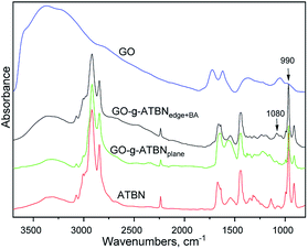
The goal of the GO modifications was to achieve the plane or edge localization of the attached ATBN chains. This is based on the Lerf–Klinovski model40 considering the dominant presence of epoxy groups in the plane area of GO, whereas the carboxyls are localized at the edges. From FTIR evaluation (Fig. 1) of thoroughly washed filter cakes, it follows that the concentration of ATBN in GO-g-ATBNedge+BA obtained by the reaction of ATBN with edge-localized carboxyls of GO modified by the reaction of epoxy groups with BA (to avoid plane-grafting) exceeds the amount of ATBN grafted using plane localized epoxy groups. This result indicates that the concentration of epoxy functionality (utilized for grafting) is most probably lower than that of carboxyls. Based on the elemental analysis, the concentration of grafted ATBN in GO-g-ATBNedge+BA was ∼55%. Another type of edge functionalization was obtained by thionyl-chloride activation of carboxyls in unmodified GO. Herein, the evolved HCl led to the simultaneous elimination of epoxy groups (Scheme 1). As a result, only the edge grafting also occurs (GO-g-ATBNedge). In this case, according to FTIR and TGA, the amount of attached ATBN was approximately lower by 20% (not shown). From Fig. 1, it further follows that the band at 990 cm−1, indicating the epoxy functionality, is overlapped by the ATBN peaks. At the same time the concentration of the characteristic amide units corresponding to edge grafting is apparently below the resolution limit of the FTIR. Therefore, only the indirect indication of plane/edge grafting based on the expected selective reactivity41 of different groups (epoxy and –COCl) of GO could be applied. Some differences in the spectra in Fig. 1 may be caused due to the interactions of GO with dioxane.42 At the same time, the band at 1080 cm−1 for GO-g-ATBNedge+BA (and GO-g-ATBNedge) samples indicates sulphite formation caused by the SOCl2 reaction with GO. | ||
| Scheme 1 Simultaneous conversion of carboxyl groups and the elimination of epoxy functionality of GO to get the precursor for edge grafting of ATBN. | ||
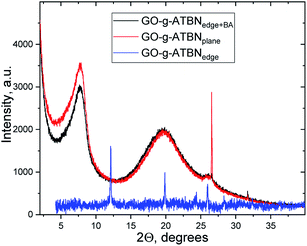
The XRD patterns (Fig. 2) of different GO-g-ATBN (in the dry-state, prepared by dipping of solvent dispersed on a glass surface) indicate the same position of the first peak (2Θ = 7.72°) for both GO-g-ATBNplane and GO-g-ATBNedge+BA samples, which corresponds to the interlayer distance of 11.44 Å. The peak width is changing, which indicates larger ordered stacks of modified GO in case of the sample with edge-attached GO (GO-g-ATBNedge+BA), whereas the peak area is larger for the plane-coupled ATBN sample. The almost 24% increase in the peak area should be directly proportional to the amount of modified GO involved in the domain formation.
The intense peak at 2Θ = 26.52 corresponds to the graphite (002) peak with the interlayer distance of 3.36 Å.43 It is accompanied by a small peak at a slightly larger 2Θ value. The peak of a similar character appears during the milling processing.44
In the case of GO-g-ATBNedge, the lower amount of edge-grafted chains together with the unmodified plane area of GO changes the structural morphology drastically. The molecules are well-packed into a fine-ordered structure. In the measured 2Θ range, the peaks were detected at the 2Θ positions = 12.42°, 19.86°, 24.28°, 25.96°, 28.32°, 36.32°, 40.34°, and 42.61°.
We consider that the differences found correspond to the self-assembling ability determined by the adduct structure, especially, the different degree and geometry of grafting.
Unfortunately, we were not able to directly confirm the geometry (localization) of the grafted ATBN; some indirect indication is the undoubtedly different morphology of the respective lamellar arrays in epoxy (see below). The same is valid for a low concentration of grafted BA, which is undetectable by FTIR.
Effect of ATBN-grafted GO on the structure
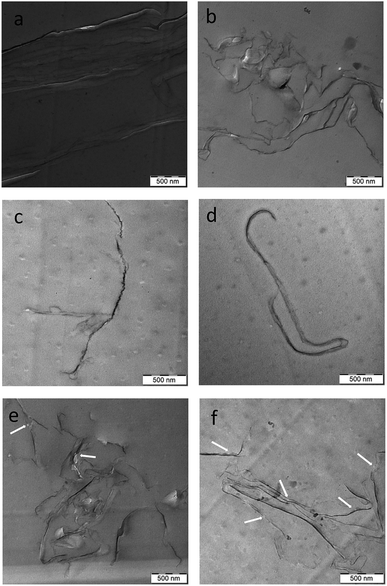
The TEM images of epoxy (Fig. 3a–c) containing all the types of pre-made GO-g-ATBN indicate the dominant formation of lamellar structures by self-pinning mechanism15 in comparison with the dispersion of single platelets in the case of unmodified GO. The formation of layered structures is apparently promoted by the amphiphilic surfactant-like structure of the GO-g-ATBN adducts together with their favourable geometry.37,38 This fact also corresponds to the well-known tendency of different platelet–polymer combinations to form nacre-like arrays.12 The TEM images also indicate the different morphology of the arrays that depend on the grafting geometry and degree, including BA coverage. Fig. 3a shows that plane modification leads to the most marked distance between the GO platelets, i.e., the most distinct elastomeric interlayer. In the both cases of edge bound ATBN, a denser lamellar structure with a less marked rubbery interlayer was created. In the case of lower extent of edge grafting and unmodified plane area of GO, marked branching of this more “tight” lamellar structure was found (Fig. 3b). Fig. 3c shows that the higher extent of edge grafting combined with BA modification of the plane area of GO leads to a different type of denser lamellae, probably also with a changed alignment type.At the same time, the creation of ordered structures also seems to be supported by the reduced solubility of ATBN in epoxy with increasing molecular weight during crosslinking, i.e., by reaction-induced phase separation (RIPS). Generally, this leads to the formation of larger domains; the formation of bulky ordered arrays can be considered as analogous to phase separation. The hypothesis of formation of these structures, at least in the early stage of RIPS (by reduced solubility of ATBN), seems to be supported by the incorporation of rubbery domains into lamellar structure in the case of simultaneously added ATBN dissolved in uncured epoxy (see below). In other words, the formation of lamellar arrays and the phase separation of ATBN seems to proceed simultaneously.
From the above results, it follows that polymer modification of GO does not lead to better exfoliation but to some kind of a thermodynamically more advantageous lamellar structure. The array formed can also be described as some kind of a rigid-tough nacre-like structure. Fig. 3d–f show that the lamellar structure is created also in the case of combination of added ATBN and GO-g-ATBN. But the changed morphology indicates a certain effect on the formation of the lamellar structure by dissolved ATBN. This leads, especially in the case of plane-grafted ATBN, to the formation of a different lamellar structure, probably with less favourable parameters (see below). Fig. 3b and c also indicate that simultaneous phase separation of the elastomer and the formation of lamellar arrays (due to RIPS) may lead to a structure with partial incorporation of the elastomer in the case of GO with both types of edge ATBN functionalization (Scheme 2).
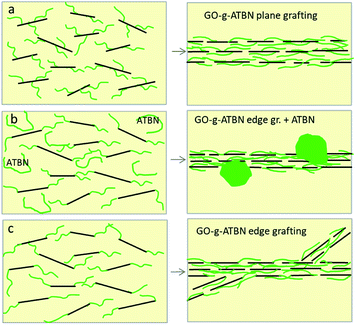 | ||
| Scheme 2 Effect of grafting geometry on the morphology of lamellar arrays (a) GO-g-ATBNplane (b) GO-g-ATBNedge (c) GO-g-ATBNedge + ATBN. | ||
Effect of separate GO + ATBN addition on the structure
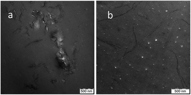
In the case of separate GO and ATBN addition directly to the epoxide, the presence of inclusions together with the lamellar structures apparently indicates the in situ formation of GO-g-ATBN. The adduct structure/degree of grafting is most probably different from the pre-made GO-g-X16 adduct, which may lead to different morphology of the lamellar structure. From comparison of Fig. 3d and 4a, it is obvious that the structure is similar to that of the plane-grafted GO-g-ATBN + 5ATBN system, where the added ATBN affects the formation of the lamellar structure (see above). In the case of reduced GO (rGO), in situ grafting does not occur, which apparently leads to the formation of a less “organized” structure of the blended inclusions (Fig. 4b). A similar kind of blended inclusions were also found in the case of the GO-g-BA + ATBN combination (not shown).XRD
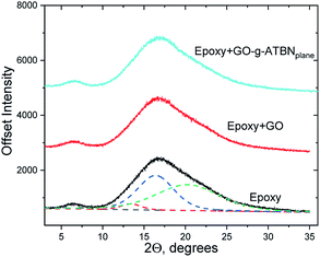
Fig. 5 indicates that all the XRD patterns of the epoxy nanocomposites look similar. These are the typical spectra observed for epoxy.4 The absence of a characteristic peak of GO could be explained by the exfoliation (or also GO concentration below resolution limit of XRD). With respect to the shape of the broad peak at 10° < 2Θ < 27°, we supposed the superposition of several peaks. The set of three Gaussian peaks describes the shape quite well. After peak decomposition, just minor differences between the peak parameters and thus, between the chain organization in the samples, were detected. The example of decomposition is shown in the neat epoxy sample. As a result, in the case of the epoxy with the lamellar structure formed by GO-g-ATBNplane, we can consider that its concentration is insufficient for XRD evaluation. Therefore, the dimensions of the elastomeric “interlayer” could be indicated by TEM only. This limitation originates from the fact that the goal of this study was to highlight only the effect of low GO concentration on the performance of epoxy.Dynamic mechanical analysis
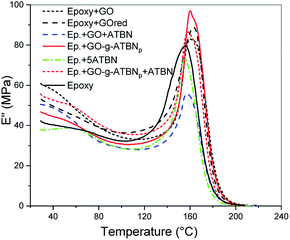
The evaluation of glass transition temperature of epoxy (Table 1 and Fig. 6) shows a slight increase due to the addition of GO. This indicates that the immobilization effect of GO probably eliminates the possible disturbance of the epoxy network formation by the reaction of the amine-hardener with the epoxy groups of GO. This negative effect of GO is confirmed by higher Tg in the case of rGO and BA-modified GO (similar ∼3 °C increase over GO); here, the reinforcing effect without a negative effect on the curing can only be considered. In the case of epoxy containing GO-g-ATBN-based lamellar structure, a slight decrease in the Tg probably corresponds to presence of the elastomer-formed interface on the surface of the arrays (together with the analogous interlayer between the GO platelets). The addition of 5% ATBN decreases the Tg, comparably for both the GO + ATBN and GO-g-ATBN + ATBN systems. The relatively low negative effect of added ATBN on Tg corresponds to a low decrease in the Tg due to ATBN in the epoxy system.| Composition | E (MPa) | σb (MPa) | εb (%) | IS (kJ m−2) | Tg (°C) |
|---|---|---|---|---|---|
| a The GO-g-ATBN concentration is related to neat GO (concentration of GO platelets is the same in all the systems). | |||||
| Epoxya | 1730 | 71 | 6 | 6.8 | 155.8 |
| +0.2GO | 2190 | 73 | 4.9 | 9.5 | 160.2 |
| +5ATBN | 1670 | 70 | 7.4 | 19 | 155.6 |
| +0.2GO + 5ATBN | 1990 | 72 | 5.4 | 14 | 157.2 |
| +0.2rGO + 5ATBN | 2040 | 65 | 5.3 | 9 | 159 |
| +0.2(GO-ATBN)plane | 2230 | 75 | 5.2 | 14.2 | 160.1 |
| +0.2(GO-ATBN)edge | 2090 | 73 | 6.1 | 12.8 | 161 |
| +0.2(GO-ATBN)edge BA | 2070 | 71 | 4.9 | 9 | 160 |
| +0.2GO-ATBNplane + 5ATBN | 2050 | 71 | 6.1 | 13.4 | 158.4 |
| +0.2GO-ATBNedge + 5ATBN | 1980 | 73 | 6.5 | 10.4 | 159 |
| +0.2GO-ATBNedge BA + 5ATBN | 1950 | 71 | 7.1 | 12 | 155 |
Mechanical properties
The results in Table 1 indicate that, in agreement with other studies, the addition of neat GO leads to enhanced modulus (E) and strength (σb), and a slight gain in the toughness (IS) of epoxy. Similar mechanical parameters were also found for the rGO-modified epoxy. The data in Table 1 further implies that the best-balanced mechanical performance is for the epoxy with low concentration of the lamellar structure formed by GO-g-ATBNplane with plane grafting using epoxy functionality, i.e., the structure with the most marked elastomeric interlayer (Fig. 3a). Its strength and stiffness exceed those achieved in all other GO/ATBN combinations, whereas the toughness is close to that of epoxy modified with ATBN only. At the same time, the edge-functionalized GO-g-ATBN with a denser lamellar structure leads to slightly worse mechanical performance, especially the toughness. This drop in the toughness was more marked for GO-g-ATBNedge+BA with a higher extent of grafting and BA “coverage” of the GO plane. This most probably corresponds to the expected different alignment type of the GO platelets (Fig. 3c).These results indicate an important effect of the morphology of the lamellar structure on the mechanical performance, especially on the impact energy absorption. Our results, especially the relative increase in E and IS with epoxy/(GO-ATBN)plane with respect to the neat epoxy, exceed those of the related study of Konnola.24 Unfortunately, as mentioned above, this work does not contain discussions of the structure formed. Table 1 further suggests that the combination of GO-g-ATBNplane with 5% added ATBN impairs the mechanical parameters, including a slight decrease in the toughness. This corresponds to the expected ATBN-induced formation of a less favourable structure of lamellar arrays in the case of plane grafted GO (Fig. 3d). The drop in the toughness also occurs in the case of edge modified GO-g-ATBN, in spite of the incorporation of rubber inclusions into the lamellar structure. This means that this modification of the lamellae apparently cannot eliminate the negative effect of the tighter lamellar structure. The only exception occurs in the case of GO-g-ATBNedge+BA with higher concentration of edge modification and plane-attached BA. Herein, a certain increase in the toughness apparently corresponds to the apparent elimination of less favourable alignment by ATBN, together with the incorporation of rubber inclusions into the lamellar array (Fig. 3f).
Similar mechanical parameters were obtained in the case of simple GO and ATBN addition. This fact well corresponds to the similar lamellae/inclusions structure (Fig. 4a). Finally, the weaker properties, especially the toughness, of epoxy with the rGO + ATBN combination are apparently a consequence of the impossibility of in situ grafting and thus the absence of GO-g-ATBN, which allows the formation of less favourable blended inclusions (Fig. 4b) only. This fact also confirms the advantages of the lamellar structure. The fact that the drop in E due to ATBN addition to GO-modified epoxy is not very marked corresponds to surprisingly low reduction in these parameters by mere ATBN addition to the selected epoxy system (Table 1).
The fracture behaviour was further described by SEM observation of the fracture surfaces of the samples broken in the impact testing.
Fig. 7a shows the smooth pattern of the fracture surface of neat epoxy, which is in contrast with the higher extent of plastic deformation and increased crack surface area due to crack deflection and pinning45 in the samples with GO/ATBN-based modifications. These changed rough patterns, indicating higher impact energy absorption capacity, are most marked for the systems with a lamellar structure (Fig. 7b), especially GO-g-ATBNplane. The smoother surface of the sample containing rGO and ATBN with less effective structure of blended inclusions is of importance (Fig. 7c). These observations well correspond to the toughness values in Table 1.
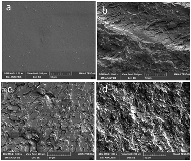 | ||
| Fig. 7 SEM images of the fracture surfaces of the samples broken by a impact hammer (a) epoxy (b) Ep. + 0.2GO-g-ATBNplane (c) Ep. + 0.2 GOred + 5ATBN (d) Ep. + 0.2GO + 5ATBN. | ||
Thermogravimetric analysis
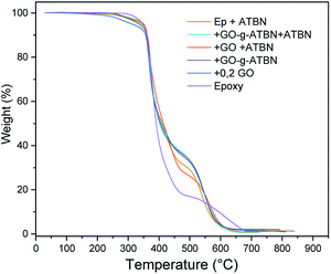
The results of TGA characterization in Fig. 8 imply enhanced thermal stability of epoxy in all the cases of GO-based modification. The combination GO + ATBN (separate addition) leads to slightly lower stability. The comparison of effect of lamellar and exfoliated structures shows negligible differences; this is probably also a consequence of the relatively low GO concentration.Conclusions
The results achieved indicate that the formation of lamellar structure leads to well-balanced mechanical properties, even with as low as 0.2% concentration of GO-g-ATBN. The low amount of GO-g-ATBN exceeds the effect of much higher amount of non-bonded liquid rubber combined with GO. In other words, the grafting of ATBN on GO is apparently its most efficient application in the epoxy system. The importance of lamellar structure morphology tailored by grafting degree and geometry, including the effect of added rubber, is highlighted. Plane grafting of ATBN leads to a favourable lamellar structure with a thicker elastomeric interlayer, whereas edge grafting leads to a less effectively dense, even branched, morphology. The addition of ATBN influences the structure formation and may also lead to the incorporation of the elastomer into the lamellar structure, which indicates that the lamellar arrays are formed in the course of crosslinking by RIPS.Conflicts of interest
There are no conflicts to declare.Acknowledgements
This work was supported by the Czech Science Foundation (Grant No 19-06065S).References
- R. Rohini, P. Katti and S. Bose, Polymer, 2015, 70, A17–A34 CrossRef CAS.
- G. Shimei, M. Lichun, S. Guojun, L. Xiaoru, L. Peiyao, W. Mingye, S. Longlong, G. Zheng and H. Yudong, J. Mater. Sci., 2018, 53, 1573–4803 Search PubMed.
- Z. Li, R. Wang, R. J. Young, L. Deng, F. Yang, L. Hao, W. Jiao and W. Liu, Polymer, 2013, 54, 6437–6446 CrossRef CAS.
- Y.-J. Wan, L.-C. Tang, L.-X. Gong, D. Yan, Y.-B. Li, L.-B. Wu, J.-X. Jiang and G.-Q. Lai, Carbon, 2014, 69, 467–480 CrossRef CAS.
- M. Gholipour-Mahmoudalilou, H. Roghani-Mamaqani, R. Azimi and A. Abdollahi, Appl. Surf. Sci., 2018, 428, 1061–1069 CrossRef CAS.
- I. Zaman, H. Kuan, Q. Meng, A. Michelmore, N. Kawashima, T. Pitt, L. Zhang, S. Gouda, L. Luong and J. Ma, Adv. Funct. Mater., 2012, 22, 2735–2743 CrossRef CAS.
- G. Li-Zhi, W. Yan-Jun, G. Li-Xiu, Y. Dong, T. Long-Cheng, W. Lian-Bin, J. Jian-Xiong and L. Guo-Qiao, J. Mater. Chem. A, 2014, 2, 15058–15069 RSC.
- M. Mehrabi-Kooshki and A. Jalali-Arani, J. Appl. Polym. Sci., 2019, 136, 46988 CrossRef.
- K. W. Kam, P. L. Teh, H. Osman and C. K. Yeoh, J. Appl. Polym. Sci., 2019, 136, 47198 CrossRef.
- T. Li, S. He, A. Stein, L. F. Francis and F. S. Bates, Macromolecules, 2016, 49(24), 9507–9520 CrossRef CAS.
- D. Quan, D. Carolan, C. Rouge, N. Murphy and A. Ivankovic, Int. J. Adhes. Adhes., 2018, 81, 21 CrossRef CAS.
- Y. Cao, J. Zhang, J. Feng and P. Wu, ACS Nano, 2011, 5, 5920–5927 CrossRef CAS PubMed.
- I. Kelnar, J. Kratochvíl, L. Kaprálková, A. Zhigunov and M. Nevoralová, J. Mech. Behav. Biomed. Mater., 2017, 71, 271–278 CrossRef CAS PubMed.
- I. Kelnar, J. Rotrekl, L. Kaprálková and J. Hromádková, J. Appl. Polym. Sci., 2012, 125, 2755–2763 CrossRef CAS.
- C. C. Chu, J. J. Lin, C. R. Shiu and C. C. Kwan, Polym. J., 2005, 37, 239–245 CrossRef CAS.
- J. Rotrekl, A. Sikora, L. Kaprálková, J. Dybal and I. Kelnar, eXPRESS Polym. Lett., 2013, 7(12), 1012–1019 CrossRef CAS.
- Y. Wang, T. Li, P. Ma, S. Zhang, H. Zhang, M. Du, Y. Xie, M. Chen, W. Dong and W. Ming, ACS Nano, 2018, 12, 6228–6235 CrossRef CAS PubMed.
- F. Wang, L. T. Drzal, Y. Qin and Z. Huang, Composites, Part A, 2016, 87, 10–22 CrossRef CAS.
- F. Wang and L. T. Drzal, Materials, 2018, 11(11), 2137 CrossRef PubMed.
- Y. J. Lim, D. Carolan and A. C. Taylor, J. Mater. Sci., 2016, 51, 8631 CrossRef CAS.
- X. Zhiguang, S. Pingan, Z. Jin, Q. Guo and Y.-W. Mai, Compos. Sci. Technol., 2018, 168, 363–370 CrossRef.
- M. G. Nasab and M. Kalaee, RSC Adv., 2016, 6(51), 45357–45368 RSC.
- T.-T. Wang, P. Huang, Y.-Q. Li, N. Hu and S.-Y. Fu, Compos. Commun., 2019, 14, 55–60 CrossRef.
- R. Konnola, J. Joj, J. Parameswranpilai and K. Joseph, RSC Adv., 2015, 5, 61775 RSC.
- Y. Li, D. Pan, S. Chen, Q. Wang, G. Pan and T. Wang, Mater. Des., 2013, 47, 850–856 CrossRef CAS.
- J. Li, W. Zhu, S. Zhang, Q. Gao, J. Li and W. Zhang, Polym. Test., 2019, 76, 232–244 CrossRef CAS.
- J. Tian, T. Xu, Y. Tan, Z. Zhang, B. Tang and Z. Sun, Materials, 2019, 12(19), 3103 CrossRef PubMed.
- J. Luo, S. Yang, L. Lei, J. Zhao and Z. Tong, Composites, Part A, 2017, 100, 275–284 CrossRef CAS.
- Y. Xie, W. Liu, C. Liu, S. He, F. Zhang, H. Shi, M. Yang and Z. Wang, J. Appl. Polym. Sci., 2019, 136, 47842 CrossRef.
- S. Laifu, L. Shaorong, X. Xiane, Q. Bo, H. Zihai, X. Xu, R. Baolin and Y. Jinhong, Polym. Bull., 2017, 74, 1611–1627 CrossRef.
- Z. S. Pour and M. Ghaemy, Compos. Sci. Technol., 2016, 136, 145–157 CrossRef.
- B. Qi, S. R. Lu, X. E. Xiao, L. L. Pan, F. Z. Tan and J. H. Yu, eXPRESS Polym. Lett., 2014, 8(7), 467–479 CrossRef CAS.
- S. Laifu, L. Shaorong, X. Xiane, Q. Bo, H. Zihai, X. Xu, R. Baolin and Y. Jinhong, Polym. Bull., 2017, 74, 1611–1627 CrossRef.
- F. Jiang, W. Zhao, Y. Wu, Y. Wu, G. Liu, J. Dong and K. Zhou, Appl. Surf. Sci., 2019, 479, 963–973 CrossRef CAS.
- C. Pignet, Dalton Trans., 2011, 40, 8059–8071 RSC.
- L. Magnus Bergström and M. Tadashi, Thermodynamics of Self Assembly, IntechOpen, 2011, DOI:10.5772/13711.
- L. Yung-Lung, C. Chi-Shiang, K. Sanat, L. Jiang-Jen, S. Yu-Jane and T. Heng-Kwong, J. Phys. Chem. C, 2011, 115, 5566–5577 CrossRef.
- H.-C. Lin, B.-Z. Hsieh, Y.-L. Lin, Y.-J. Sheng and J.-J. Lin, J. Colloid Interface Sci., 2012, 387, 106–114 CrossRef CAS PubMed.
- D. C. Marcano, D. V. Kosynkin, J. M. Berlin, A. Sinitskii, Z. Sun, A. Slesarev, L. B. Alemany, W. Lu and J. M. Tour, ACS Nano, 2010, 4, 4806–4814 CrossRef CAS PubMed.
- H. He, J. Klinowski, M. Forster and A. Lerf, Chem. Phys. Lett., 1998, 287, 53–56 CrossRef CAS.
- I. A. Vacchi, C. Spinato, J. Raya, A. Bianco and C. Ménard-Moyon, Nanoscale, 2016, 8, 13714–13721 RSC.
- D. Cortés-Arriagada, S. Miranda-Rojas, D. E. Ortega and A. Toro-Labbé, Phys. Chem. Chem. Phys., 2017, 19, 17587–17597 RSC.
- H.-K. Jeong, Y. P. Lee, R. J. W. E. Lahaye, M.-H. Park, K. H. An, I. J. Kim, C.-W. Yang, C. Y. Park, R. S. Ruoff and Y. H. Lee, J. Am. Chem. Soc., 2008, 130, 1362–1366 CrossRef CAS PubMed.
- Z. Q. Li, C. J. Lu, Z. P. Xia, Y. Zhou and Z. Luo, Carbon, 2007, 45, 1686–1695 CrossRef CAS.
- N. Domun, H. Hadavinia, H. T. Zhang, T. Sainsbury, G. H. Liaghat and S. Vahid, Nanoscale, 2015, 7, 10294–10329 RSC.
| This journal is © The Royal Society of Chemistry 2020 |

