 Open Access Article
CO2 conversion into methanol under ambient conditions using efficient nanocomposite photocatalyst/solar-energy materials in aqueous medium†
Mohsen Lashgari *ab and
Sanaz Soodia
aChem. Dept, Institute for Advanced Studies in Basic Sciences (IASBS), 444 Prof. Yousef Sobouti Blvd., Zanjan 45137-66731, Iran. E-mail: Lashgari@iasbs.ac.ir
bCenter for Research in Climate Change and Global Warming: Hydrogen and Solar Division, Zanjan 45137-66731, Iran
First published on 16th April 2020
Abstract
A promising route to solve the CO2 issue is its photocatalytic back-conversion to H-based solar fuels/chemicals, particularly methanol – being widely used as a strategic material in chemical/energy-related industries. Herein, the authors address this globally interesting problem and demonstrate how through an effortless hydrothermal route and using earth-abundant elements, two efficient carbon nanotube (CNT)-based heterojunction photocatalyst/solar-energy materials, viz. CNT/NiO and CNT/NiO/Fe2O3 are synthesized and employed for methanol production. The investigations revealed that both binary and ternary composites could selectively (≥93%) produce methanol using CO2 feed in aqueous medium. Moreover, a higher performance (energy efficiency: 1.81%) was witnessed for the ternary photocatalyst. From a catalytic standpoint, the superior activity of the CNT/NiO/Fe2O3 photocatalyst was discussed in detail in terms of its larger surface area, higher absorption of incident light, better charge separation/transfer, and generation of greater photo-voltage/current to effectually split the water medium and achieve the photoconversion process. A mechanistic scheme was finally proposed for the production of methanol and methane, as liquid and gas phase products, respectively.
Introduction
Methanol (CH3OH) is a strategic chemical with wide application in the synthesis of hydrocarbons, plastics, pharmaceuticals, adhesives and so forth. This compound is also important from an energy perspective and is considered a safe H-based fuel – that is employed in direct methanol fuel cells or utilized as a blend with gasoline in internal combustion engines.1,2Current technologies to synthesize methanol are mainly based on production and consumption of syngas mixture [the output of steam reforming process], being industrially carried out under harsh high temperature/pressure conditions (T = 200–300 °C, P = 5–10 MPa) through catalytic hydrogenation of a CO2/CO feed:2,3
 | (1) |
During the hydrogenation process, H2 molecules are dissociated upon the catalyst surface and the resulting H atoms are combined with CO2/CO molecules and transformed into methanol. Although methanol can be synthesized by either CO or CO2 feed, the use of CO2 is preferred from non-toxicity standpoint.4,5
Carbon dioxide transformation [back-conversion] into methanol is also crucial from the environmental viewpoint,1 since this notorious greenhouse gas – being unrestrictedly produced by human societies and dumped into the atmosphere – is universally deemed the main cause of global warming and climate change.6 Therefore, this plentiful ubiquitous gas can be reconsidered a sustainable complimentary source of carbon and be utilized in the synthesis of other C-based chemicals/fuels,7,8 particularly methanol as pointed above.
Artificial photosynthesis of methanol using CO2 upon semiconductor materials in aqueous medium, is a modern/green strategy,9 in which H atoms (radicals) are transiently generated on the photocatalyst surface (H+ + ecb− → H10) and subsequently utilized in CO2 conversion (hydrogenation) to methanol.
One of the challenging issues in the photocatalytic back-conversion of CO2 into oxygenates is selective synthesis of a specific compound and reduction of the diversity of by-products.7,11 This objective can be met by proper selection of photocatalyst components.12 In the present work, we chose NiO semiconducting component, owing to nickel property in CO2 adsorption and its capability to produce methanol.4,13,14 We also employed carbon nanotube (CNT), because it has been reported as an effective component for photocatalytic conversion of CO2 into solar fuels, particularly alcohols.9,15,16 Furthermore, it is worth noting that CNT has the capacity of hydrogen storage.17 Therefore, on the resulting CNT/NiO composite material, the hydrogenation of CO2 could occur effectively, and an appreciable amount of methanol is anticipated to be produced upon this binary nanocomposite photocatalyst.
Since NiO is a wide-bandgap, p-type semiconducting material, a straightforward strategy to improve its photon absorption and reduce charge (e/h) recombination phenomenon, is to make its composite with a suitable low-cost, eco-friendly, narrow-bandgap, n-type semiconductor, viz. Fe2O3.8,18–20 Based on this strategy, herein, we also synthesized a ternary CNT/NiO/Fe2O3 composite as an efficient photocatalyst/solar-energy material for application in CO2 transformation into methanol. Concerning the photocatalytic application of NiO/Fe2O3, it should be finally noted that these semiconducting components have been also employed in the literature, for water oxidation and dye (pollutant) degradation as well.18,19,21,22
The objective of this research is to reduce the diversity of products and perform selective photosynthesis of methanol by means of proper selection of photocatalyst components and their synthesis through a facile hydrothermal route using earth abundant elements. To better understanding of the photocatalyst activity, besides geometrical/morphological as well as photochemical factors, we will also pay particular attention on photoelectrochemical concepts, including photovoltage and photocurrent as two new thermodynamic and kinetic parameters influencing on the activity of photocatalysts. Another interesting feature of this article is its mechanistic interpretation of the photosynthesis phenomenon.
Experimental
Photocatalyst synthesis
The binary and ternary composite energy-materials, i.e. CNT/NiO and CNT/NiO/Fe2O3 were hydrothermally synthesized according to the literature with some modifications.23–26 Prior to the synthesis of photocatalysts, CNT (multiwall, purchased from Neutrino CNT-manufacturing company; internal and external diameters 3 and 6.3 nm, respectively17) was thoroughly washed and dispersed using a sonication bath in acetone (30 min), ethanol (1 h), and deionized water (DW, 30 min) and finally dried in a vacuum desiccator overnight at room temperature. To synthesize CNT/NiO, an appropriate quantity of the purified CNT [3 wt%; Fig. S1†] was ultrasonically dispersed in a 30 ml DW/ethanol (1![[thin space (1/6-em)]](https://www.rsc.org/images/entities/char_2009.gif) :
:![[thin space (1/6-em)]](https://www.rsc.org/images/entities/char_2009.gif) 1 v/v) solution containing 0.12 M Ni2+ (NiCl2·6H2O salt, Sigma-Aldrich; 99%), 0.07 M hexamethylenetetramine (C6H12N4, Merck; 99%), and 2 ml ethanolamine (NH2(CH2)2OH, Merck; 98%). The suspension was then transferred into a Teflon-lined stainless steel autoclave and heated for a day at 160 °C. After cooling the reactor, the reaction mixture was decanted, washed several times with ethanol and DW, and dried at 60 °C. Finally, the resulting compound was heated (5 °C min−1) under argon atmosphere, and stayed at 350 °C for 1 h.
1 v/v) solution containing 0.12 M Ni2+ (NiCl2·6H2O salt, Sigma-Aldrich; 99%), 0.07 M hexamethylenetetramine (C6H12N4, Merck; 99%), and 2 ml ethanolamine (NH2(CH2)2OH, Merck; 98%). The suspension was then transferred into a Teflon-lined stainless steel autoclave and heated for a day at 160 °C. After cooling the reactor, the reaction mixture was decanted, washed several times with ethanol and DW, and dried at 60 °C. Finally, the resulting compound was heated (5 °C min−1) under argon atmosphere, and stayed at 350 °C for 1 h.
To synthesize CNT/NiO/Fe2O3, 10 mg of the freshly prepared CNT/NiO powder was added to 16 ml DW containing 0.032 M sodium sulfate salt (Na2SO4·10H2O, Sigma-Aldrich; 98%). Under vigorous stirring of the mixture, an optimum quantity of Fe3+ cation [2![[thin space (1/6-em)]](https://www.rsc.org/images/entities/char_2009.gif) :
:![[thin space (1/6-em)]](https://www.rsc.org/images/entities/char_2009.gif) 1 Fe3+ to Ni2+ molar ratio; see Fig. S1†], i.e. 240 mmol ferric nitrate (Fe(NO3)3·9H2O salt, Sigma-Aldrich; 98%) was dissolved in the mentioned medium. The resulting mixture was then transferred into the autoclave reactor and heated for 2 h at 120 °C. After cooling the reactor, the precipitate was similarly washed several times with ethanol and DW, dried at 80 °C and finally calcined at 400 °C under argon atmosphere for 2 h (heating rate: 5 °C min−1).
1 Fe3+ to Ni2+ molar ratio; see Fig. S1†], i.e. 240 mmol ferric nitrate (Fe(NO3)3·9H2O salt, Sigma-Aldrich; 98%) was dissolved in the mentioned medium. The resulting mixture was then transferred into the autoclave reactor and heated for 2 h at 120 °C. After cooling the reactor, the precipitate was similarly washed several times with ethanol and DW, dried at 80 °C and finally calcined at 400 °C under argon atmosphere for 2 h (heating rate: 5 °C min−1).
Characterization (XRD, XPS, Raman, SEM, BET, DR, PL, and photoelectrochemical analyses)
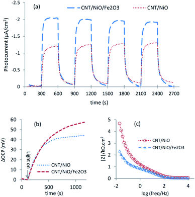
X-ray diffraction (XRD) patterns of the synthesized materials were determined using a Philips X'Pert Pro X-ray powder diffractometer (λ = 1.54 Å; Cu-Kα beam). XPS spectra were recorded via a Thermo Scientific™ ESCALAB™ 250Xi photoelectron spectrometer with Mg-Kα X-ray source (1253.6 eV). Raman spectra were recorded at room temperature using a Rigaku FirstGuard hand-held spectrometer with a 1064 nm laser and TE (Thermoelectric) Cooled CCD (Charge Coupled Device) detector. Field emission scanning electron micrographs (FE-SEM) of the synthesized materials were taken using a Tescan Mira3 electron microscope. Nitrogen adsorption–desorption (BET) and porosimetry tests were conducted at 76 K on a Micromeritics® TriStar II Plus analyzer. Diffuse reflectance (DR) spectra of the photocatalysts were measured using a Varian Cary 5 UV-Vis-NIR spectrometer (BaSO4 was used as a blank). To record photoluminescence (PL) spectra of the photocatalyst materials, a Varian Cary Eclipse fluorescence spectrophotometer was utilized (λex = 409 nm).Open circuit potential (OCP), transient photocurrent and impedance measurements of the photocatalyst powders were conducted in a conventional 3-electrode glass cell using an Ivium-Vertex Potentio-Galvanostat instrument (electrolyte: a 0.5 M NaHCO3 solution, light source: a 10 W blue LED with λ = 434 nm).7,17 In these tests, a platinum foil (2.5 cm2) and saturated calomel (SCE) were employed as counter and reference electrodes, respectively. The working electrodes (WEs) were also fabricated through a Dr Blade approach27 by mixing 20 mg photocatalyst, 3 drops Triton X-100 (surfactant, serving as binder) and 0.25 ml DW, and coating the resulting paste on the conductive side of a 1 × 1 cm2 fluorine doped tin oxide (FTO) glass (SOLARONIX, electrical resistance: 10 Ω sq−1). Then, the electrodes were dried at 60 °C for 15 min and finally annealed at 250 °C for 60 min. By applying a small potential bias to WE (∼10 mV w.r.t. OCP), the transient photocurrent tests were carried out under a situation, where the background (dark) current was almost zero and its sign was not changed during the light-on/off cycles [OCPs for CNT/NiO and CNT/NiO/Fe2O3 were ∼295 and 287 mVSCE, respectively].
Photocatalytic conversion of CO2 into methanol: photoreactor setup and product analysis
The photoconversion/hydrogenation process was conducted in an upright, cylindrical, double-wall, glass reactor attached to a T-controlling bath circulator (WCR-P6). The reaction medium was 50 ml DW containing 50 mg suspended photocatalyst and dissolved CO2 gas. To increase the solubility of the gas as well as improve the photocatalyst performance, the pH of medium was set at 8.5 using a NaOH solution.7,28 Prior to illumination of the reactor, the medium was saturated with a pure 99.99% CO2 gas (under saturated condition, the pH of medium reaches ∼7.5 and bicarbonate is the predominant species in the medium29,30). During the test, the photocatalyst particles were continuously dispersed using a magnetic stirrer, and the bubbling of CO2 gas into the reaction medium continued in a smooth flow (∼40 ml min−1). A sun simulated light (xenon irradiation, 100 mW cm−2)17 was employed and the tests were terminated after 2 h illumination of the reactor (according to our previous reports, the illumination at longer periods is not recommended for the studies of liquid-phase products, because by accumulating the product in the reaction medium, it can undergo further reaction/degradation and becomes consequently consumed7,9).The water photo-splitting experiment was conducted in the same photoreactor (containing 50 ml DW and 50 mg photocatalyst powder) in the absence of any additive, and the volume of photogenerated gas was recorded at different illumination periods in a route described in detail elsewhere.31,32
The quantity of methanol and other by-products in the aqueous reaction medium was determined using a high performance liquid chromatographic (HPLC) approach.33,34 To this end, a Knauer HPLC instrument equipped with UV and RI detectors (K2600, K2310) and a Eurokat H column (300 × 8 mm, 10 μm) was applied [eluent: 0.05 M H2SO4, temp: 60 °C, flow rate: 0.6 ml min−1]. All measurements were repeated at least three times and the mean values were reported as final data.
Results and discussion
Photocatalyst synthesis and characterization
X-ray diffraction (XRD) patterns of the binary (CNT/NiO) and ternary (CNT/NiO/Fe2O3) nanocomposites are depicted in Fig. 1.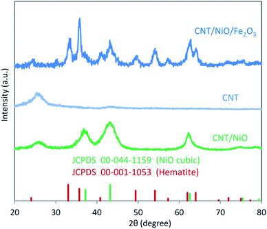 | ||
| Fig. 1 X-ray diffraction (XRD) patterns of the binary and ternary CNT-based photocatalyst/solar-energy materials synthesized in this work. | ||
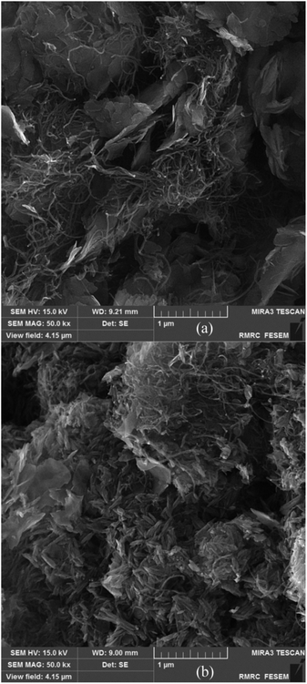
Similar to our previous reports, the existence of CNT in these composite materials is recognized as a relatively wide, low-intensity peak between 20 to 30 degrees.8,33 By comparing the XRD pattern of CNT/NiO with that of NiO (JCPDS card no. 00-044-1159), the formation of the binary composite is clearly affirmed. Furthermore, the occurrence of wide peaks in XRD diagrams indirectly indicates that the energy materials synthesized here have nanostructured morphology.9,31 Fig. 1 also shows that compared to the XRD diagram of CNT/NiO, the ternary composite, i.e. CNT/NiO/Fe2O3 has a more complicated pattern, which is owing to the existence of Fe2O3 component (JCPDS card no. 44-1159) in this composite material. In addition to XRD, the presence of Ni, Fe, O, C and the formation of NiO, Fe2O3 and CNT were confirmed using XPS data (Table 1). The synthesis of NiO and Fe2O3 as well as the existence of CNT in the composite material were also approved by Raman evidence (Fig. S4†). The nanostructured morphology witnessed via XRD diagram (peak broadening; see Fig. 1) was confirmed by SEM images taken from both binary and ternary photocatalysts (Fig. 2). Fig. 2a shows a porous nano-flake/flower-like structure (the characteristic of NiO23–25) in which CNT fibers are distributed in a relatively uniform manner within the composite photocatalyst. Besides NiO nano-flakes and CNT fibers, in the SEM image of the ternary photocatalyst (Fig. 2b), the existence of Fe2O3 was recognized as rod-shaped entities (see also Fig. S5 and S6†). The porous morphology of the photocatalysts was approved through BET analyses (Table 2 and Fig. S7†); here, a mesoporous structure (pore diameter: ∼12 nm) was obtained for both photocatalysts, and a larger surface area as well as more pore volume were found in the presence of Fe2O3 component.
Optical/photo-electrochemical response and activity prediction
Fig. 3a shows that CNT/NiO has a fair photon absorption in the visible region. This interesting ability of the photocatalyst to absorb incident light is ascribed to the existence of CNT in the composite material17 (Fig. S8†). By adding Fe2O3 to the binary composite, the extent of photon absorption increases and its bandgap decreases from 2.7 eV to 1.6 eV (see Fig. S10†). Fig. 3b displays lower PL emission for the CNT/NiO/Fe2O3 photocatalyst, indicating the existence of a greater opportunity for the photogenerated charges in this photocatalyst to be effectually consumed in the photoredox process, before they get naturally annihilated through the e/h recombination phenomenon.36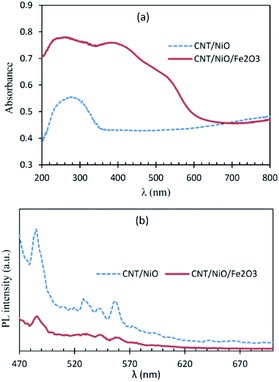 | ||
| Fig. 3 Diffuse reflectance (DR) UV-Vis (a) and photoluminescence (PL; (b)) spectra of the nanocomposite photocatalyst/solar-energy materials under study. | ||
The better charge separation witnessed for the ternary composite was reconfirmed by photo-electrochemical studies (Fig. 4), as a producing a higher transient photocurrent and greater photo-voltage [shift in OCP due to system illumination] as well as less electrical resistance (impedance) against charge transport.37 Because of these reasons and the superior potency in harnessing the incident photons as well as possessing a larger surface area (Table 2), the ternary composite is anticipated to exhibit higher activity to convert CO2 into methanol [see the next section].
CO2 photoreduction in aqueous medium, methanol synthesis, and mechanistic perspective
CO2 photoreduction reaction in the aqueous medium was performed under ambient conditions in the presence of binary and ternary composites, and the results of products analysis are summarized in Table 3.| Product (μM) | Methanol | Oxalic acid | Formic acid | Acetic acid |
|---|---|---|---|---|
| a,b data listed in these parentheses (rows) denote respectively to the selectivity (%) and energy efficiency (%), obtained for the photoconversion process to produce a specific product upon the photocatalyst material. | ||||
| CNT/NiO | 1655.0 | 64.5 | 33.1 | Trace |
| (94.4)a | (3.7) | (1.9) | — | |
| (0.68)b | (0.08) | (0.01) | — | |
| CNT/NiO/Fe2O3 | 4382.0 | 179.2 | 114.3 | 41.7 |
| (92.9)a | (3.8) | (2.4) | (0.9) | |
| (1.81)b | (0.24) | (0.05) | (0.02) | |
Table 3 indicates that methanol is the main product of the CO2 photoreduction process; by adding Fe2O3 to the binary composite, the capability of photocatalyst to produce methanol increases significantly (∼2.6 times). To determine the ability of photocatalysts in selective production of methanol [among the liquid phase products], the authors employed this formula:
 | (2) |
 | (3) |
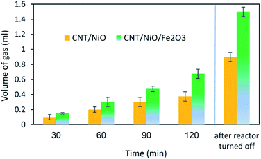
Briefly, the superior activity of the ternary composite photocatalyst can be rationalized to its ability in: (1) possessing a larger surface area, (2) absorbing more incident photons, (3) exhibiting less charge (e/h) recombination, (4) facilitating charge transfer, and (5) producing more photo-voltage (photo-generated electromotive force). Furthermore, it should be noted that the ternary photocatalyst has greater potency in utilizing photogenerated charges  to split water medium; see Fig. 5. The redox reactions occurring during the water-splitting process are proton reduction (eqn (4)) and hydroxide oxidation (eqn (5)), and the overall process is splitting of H2O molecules:17,38
 | (4) |
 | (5) |
 | (6) |
Concerning the capability of photocatalysts to split H2O, Fig. 5 demonstrates that both composites are able to perform the water splitting process and the superior activity is due to CNT/NiO/Fe2O3. This evidence proposes the conjecture that during the water splitting process, not only more hydrogen but more hydroxyl could also be transiently generated upon the ternary photocatalyst surface.10 With the generation of more H/OH radicals and facilitation of the hydrogenation of methoxyl or hydroxylation of methyl radicals (eqn (7)), the production of greater quantity of methanol (Fig. 6) is rationalized:11,39–41
 | (7) |
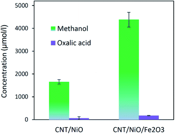 | ||
| Fig. 6 The power of photocatalysts to convert CO2 into methanol and oxalic acid (the main liquid-phase by-product). | ||
In connection with this mechanistic route, it should also be noted that the transient generation of radical species mentioned above has been already witnessed elsewhere through EPR (electron paramagnetic resonance) and in situ FT-IR (Fourier transform infrared) spectroscopic techniques.5,11,12,41–44
The other point – deducing from eqn (7), is the possibility of ĊH3 + Ḣ recombination and hence the generation of methane as a gas-phase product. This anticipation was just verified for the ternary photocatalyst – that is able to produce extra methanol [see Fig. 6 and S12†]. Furthermore, it is worth noting that the non-production of methane upon the binary photocatalyst can be used to elucidate why less methanol becomes produced on CNT/NiO photocatalyst; here, the lack of methane formation (CḢ + Ḣ ↛ CH4) signifies that the available route for the methanol production is CH3Ȯ + Ḣ reaction not ĊH3 + ȮH alternative. By contrast, in the case of ternary photocatalyst, since methane is produced (ĊH3 + Ḣ → CH4), both reaction channels (eqn (7)) are available; therefore, the production of more quantity of methanol is justified.
The final interesting fact that can be deduced from Fig. 5 is concerned with the H-sorbing capacity of CNT, justifying why by ending the reactor illumination, the gas evolution process is not immediately stopped. From photo-transformation standpoint, this property of the catalyst component is important, because CNT could indeed serve as an in situ H-reservoir system13 for the hydrogenation of CO2 on the photocatalyst surface.
Conclusions
As a synopsis, in the present study, the authors focussed on the matter of selective photocatalytic transformation of CO2 into methanol. To this end, two effective, eco-friendly, affordable CNT-based heterojunction nanocomposite photocatalysts were synthesized through a facile hydrothermal route. It was proved that both photocatalyst/solar-energy materials were able to selectively (≥93%) photosynthesize methanol. Since photocatalytic phenomena have an electrochemical nature, i.e. within them, a couple of redox (electron transport) reactions occur synchronously on the photocatalyst surface, these photo-induced phenomena could be electrochemically characterized via measuring the photogenerated voltage and current as two new determinant factors in the evaluation (justification) of the photocatalysts activity. Here, photovoltage (generated by striking photons onto the photocatalyst surface) plays a role of driving (electromotive) force for performing the redox reactions and photocurrent is the rate of electron transport, which could roughly represent a kinetic feature of the process. Besides points mentioned above, the following remarks were concluded:❖ In the absence of any additive (sacrificial agent), both photocatalysts were able to split water molecules and serve as in situ H generator for CO2 hydrogenation to methanol.
❖ With addition of Fe2O3 to the binary composite (CNT/NiO), not only the system impedance decreased, but its surface area as well as its potency to effectually harness incident photons were increased. Upon the resulting ternary photocatalyst (CNT/NiO/Fe2O3), a greater amount of methanol (more than twice) was produced.
❖ In the case of CNT/NiO/Fe2O3, by illuminating the reaction medium, a larger photo-voltage/current was generated and the splitting of water molecules as well as methanol production occurred in a superior extent.
❖ For methanol synthesis upon the ternary photocatalyst, both ĊH3 + ȮH and CH3Ȯ + Ḣ reaction channels were available and methane (ĊH3 + Ḣ) was the main gas-phase product. Whereas in the case of binary photocatalyst, the reaction channel was limited to CH3Ȯ + Ḣ and no methane was produced.
Conflicts of interest
There are no conflicts to declare.Acknowledgements
The authors wish to acknowledge the research council of IASBS for financial support of this project (GIASBS201932603). SS should thank Prof. Andreas Züttel for her hosting at EPFL and Lab facility for GC tests of gaseous products. We would also like to extend our thanks to the Editor as well as anonymous Referees of the manuscript for their efforts and useful comments.Notes and references
- G. A. Olah, Angew. Chem., Int. Ed., 2005, 44, 2636 CrossRef CAS PubMed.
- S. G. Jadhav, P. D. Vaidya, B. M. Bhanage and J. B. Joshi, Chem. Eng. Res. Des., 2014, 92, 2557 CrossRef CAS.
- F. Studt, M. Behrens, E. L. Kunkes, N. Thomas, S. Zander, A. Tarasov, J. Schumann, E. Frei, J. B. Varley, F. Abild-Pedersen, J. K. Nørskov and R. Schlçgl, ChemCatChem, 2015, 7, 1105 CrossRef CAS.
- F. Studt, I. Sharafutdinov, F. Abild-Pedersen, C. F. Elkjær, J. S. Hummelshøj, S. Dahl, I. Chorkendorff and J. K. Nørskov, Nat. Chem., 2014, 6, 320 CrossRef CAS PubMed.
- W. Wang, S. Wang, X. Ma and J. Gong, Chem. Soc. Rev., 2011, 40, 3703 RSC.
- M. Lashgari, Use of solar and alternative energy to reduce emissions, US-Iran Symposium on Climate Change: Impacts and Mitigation, March 30–April 1, Irvine, California, 2015 Search PubMed.
- M. Lashgari and S. Soodi, J. Nanosci. Nanotechnol., 2019, 19, 3237 CrossRef CAS PubMed.
- Z. Yang, J. Xu, C. Wu, H. Jing, P. Li and H. Yin, Appl. Catal., B, 2014, 156–157, 249 CrossRef CAS.
- M. Lashgari, S. Soodi and P. Zeinalkhani, J. CO2 Util., 2017, 18, 89 CrossRef CAS.
- M. Lashgari and P. Zeinalkhani, Appl. Catal., A, 2017, 529, 91 CrossRef CAS.
- J. Fu, K. Jiang, X. Qiu, J. Yu and M. Liu, Mater. Today, 2020, 32, 222 CrossRef.
- X. Li, J. Yu, M. Jaroniec and X. Chen, Chem. Rev., 2019, 119, 3962 CrossRef CAS PubMed.
- X. Feng, J. I. Cerdá and M. Salmeron, J. Phys. Chem. Lett., 2015, 6, 1780 CrossRef CAS PubMed.
- X. Shao, X. Yin and J. Wang, J. Colloid Interface Sci., 2018, 512, 466 CrossRef CAS PubMed.
- M. I. Malik, Z. O. Malaibari, M. Atieh and B. Abussaud, Chem. Eng. Sci., 2016, 152, 468 CrossRef.
- M. M. Kandy, Sustainable Energy Fuels, 2020 10.1039/C9SE00827F.
- M. Lashgari and P. Zeinalkhani, Nano Energy, 2018, 48, 361 CrossRef CAS.
- J. Li, F. Meng, S. Suri, W. Ding, F. Huang and N. Wu, Chem. Commun., 2012, 48, 8213 RSC.
- S. Jana, A. Mondal and A. Ghosh, Appl. Catal., B, 2018, 232, 26 CrossRef CAS.
- J. Wang, H. Liu, Y. Xu and X. Zhang, Asian J. Chem., 2014, 26, 3875 CrossRef CAS.
- X. Du, J. Wei, J. Zhao, R. Han and Y. Ding, Chem.–Asian J., 2014, 9, 2745 CrossRef CAS PubMed.
- H. Bemana and S. Rashid-Nadimi, Surf. Interfaces, 2019, 14, 184 CrossRef CAS.
- Y. Jiao, Y. Liu, B. Yin, S. Zhang, F. Qu and X. Wu, Nano Energy, 2014, 10, 90 CrossRef CAS.
- C. Wang, X. Cheng, X. Zhou, P. Sun, X. Hu, K. Shimanoe, G. Lu and N. Yamazoe, ACS Appl. Mater. Interfaces, 2014, 6, 12031 CrossRef CAS PubMed.
- X. Zhang, C. Wang, H. Li, X. G. Wang, Y. N. Chen, Z. Xie and Z. Zhou, J. Mater. Chem. A, 2018, 6, 2792 RSC.
- S. M. Bashir, S. S. Hossain, S. Rahman, S. Ahmed and M. M. Hossain, Electrocatalysis, 2015, 6, 544 CrossRef CAS.
- M. Lashgari and M. Ghanimati, Chem. Eng. J., 2019, 358, 153 CrossRef CAS.
- M. A. Asi, L. Zhu, C. He, V. K. Sharma, D. Shu, S. Li, J. Yang and Y. Xiong, Catal. Today, 2013, 216, 268 CrossRef.
- C. B. Andersen, J. Geosci. Educ., 2002, 50, 389 CrossRef.
- J. G. Shim, D. W. Lee, J. H. Lee and N. S. Kwak, Environ. Eng. Res., 2016, 21, 297 CrossRef.
- M. Lashgari and M. Ghanimati, J. Photonics Energy, 2014, 4, 044099 CrossRef.
- M. Lashgari and M. Ghanimati, J. Colloid Interface Sci., 2019, 555, 187 CrossRef CAS PubMed.
- J. Hong, W. Zhang, J. Ren and R. Xu, Anal. Methods, 2013, 5, 1086 RSC.
- R. Gusain, P. Kumar, O. P. Sharma, S. L. Jain and O. P. Khatri, Appl. Catal., B, 2016, 181, 352 CrossRef CAS.
- Y. Wang, S. Fan, F. Liao, X. Zheng, Z. Huang, Y. Wang and X. Han, Nanoscale Adv., 2019, 1, 1200 RSC.
- M. Lashgari and M. Ghanimati, J. Hazard. Mater., 2018, 345, 10 CrossRef CAS PubMed.
- M. Lashgari, P. Elyas-Haghighi and M. Takeguchi, Sol. Energy Mater. Sol. Cells, 2017, 165, 9 CrossRef CAS.
- M. Lashgari and D. Matloubi, J. Chem. Sci., 2015, 127, 575 CrossRef CAS.
- Z. Sun, N. Talreja, H. Tao, J. Texter, M. Muhler, J. Strunk and J. Chen, Angew. Chem., Int. Ed., 2018, 57, 7610 CrossRef CAS PubMed.
- X. M. Liu, G. Q. Lu, Z. F. Yan and J. Beltramini, Ind. Eng. Chem. Res., 2003, 42, 6518 CrossRef CAS.
- N. M. Dimitrijevic, B. K. Vijayan, O. G. Poluektov, T. Rajh, K. A. Gray, H. He and P. Zapol, J. Am. Chem. Soc., 2011, 133, 3964 CrossRef CAS PubMed.
- J. Wambach, A. Baiker and A. Wokaun, Phys. Chem. Chem. Phys., 1999, 1, 5071 RSC.
- H. Yamashita, A. Shiga, S. Kawasaki, Y. Ichihashi, S. Ehara and M. Anpo, Energy Convers. Manage., 1995, 36, 617 CrossRef CAS.
- Y. Jia, Y. Xu, R. Nie, F. Chen, Z. Zhu, J. Wang and H. Jing, J. Mater. Chem. A, 2017, 5, 5495 RSC.
Footnote |
| † Electronic supplementary information (ESI) available. See DOI: 10.1039/d0ra01733g |
| This journal is © The Royal Society of Chemistry 2020 |

