 Open Access Article
Two novel aromatic hydrocarbons: facile synthesis, photophysical properties and applications in deep-blue electroluminescence†
Zhixiang Gaoa,
Yuling Wu *b,
Wenshan Qua,
Tianbao Lib,
Tingting Yanga,
Xiaxia Fana,
Lijuan Donga,
Yunlong Shia,
Xuerui Cheng
 c,
Yufen Renc and
Peng Tao
 *b
*b
aSchool of Physics and Electronic Science, Shanxi Datong University, Datong, 037009, P. R. China
bKey Laboratory of Interface Science and Engineering in Advanced Materials, Ministry of Education, Taiyuan University of Technology, Taiyuan, 030024, China. E-mail: wuyuling@tyut.edu.cn; iamtaopeng@gmail.com
cDepartment of Technology and Physics, Zhengzhou University of Light Industry, Zhengzhou, 450002, P. R. China
First published on 28th April 2020
Abstract
Two efficient novel fluorescent naphthalene and fluorene-based aromatic hydrocarbon isomers (1 and 2) are prepared and investigated for organic electroluminescence. These compounds show bright violet to deep-blue emission, narrow full width at half maximum (52 nm), and high photoluminescence efficiency (e.g. 0.61 in CH2Cl2, 0.67 in film). Alternation of substituent position on the naphthalene moiety can give rise to remarkable emission variation. The relatively large torsion angle between naphthalene and fluorene suppresses the π–π interactions by weakening the intermolecular interactions in the solid state, which can result in highly efficient fluorescence. Moreover, the 1931 Commission Internationale de L'Eclairage coordinates and maximum emission peak for deep-blue electroluminescence based on 1 are (0.16, 0.08) and 410 nm, respectively.
1. Introduction
Recently, wet-processable organic light-emitting devices (OLEDs) have become a research focus in the industrialization of high-performance organic electroluminescence (EL). For both solid-state lighting and displays, blue emission is indispensable.1 The inherent defects of pure blue emitters can remarkably influence the OLEDs performance, thereby hampering industrialization of OLEDs.2 Currently, most of the blue emitters suitable for wet-processable OLEDs are polymer-based materials, in which polyfluorene is the most used.3 However, the well-known shortcoming of polyfluorene is its green emission band due to the formation of a β-phase of the polymer in the aggregation state, reducing the color purity of the blue emission.3a Besides, compared to the small molecule-based emitters with well-defined chemical structure, the device performance of polymer-based OLEDs is usually unstable due to the difference in molecular weight distribution.4 Thus, structural design becomes the key to solving these problems. Fluorene is an important building block for designing blue emitters, and has inspired us to further explore this rich family of blue fluorophors through structural design for achieving wet-processable deep-blue OLEDs.In this contribution, by linking naphthalene and hexyl functionalized fluorene with large torsion angle, two novel wet-processable violet to deep-blue fluorescent aromatic hydrocarbon-based emitters (1 and 2) were designed. Hexyl chains in the fluorene moiety could not only increase their solubilities in the commonly used organic solvents but also can act as the steric hindrance group. The large torsion angle between naphthalene and fluorene unit could also suppress the π–π interactions in the solid states, inducing highly efficient emission. These two designed emitters exhibit intensive violet to deep-blue fluorescence (415 nm for 1 and 400 nm for 2 in dichloromethane) with quite high photoluminescence (PL) efficiency (ΦPL) (0.42–0.67) and narrow full width at half maximum (FWHM) (52–60 nm) beneficial to highly efficient wet-processable deep-blue OLEDs. The 1931 Commission Internationale de L'Eclairage coordinate and maximum emission peak for deep-blue electroluminescence based on 1 are (0.16, 0.08) and 410 nm, respectively.
2. Results and discussion
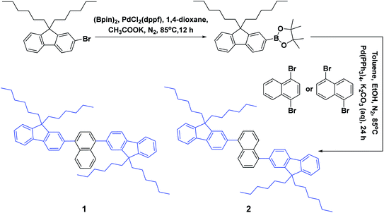
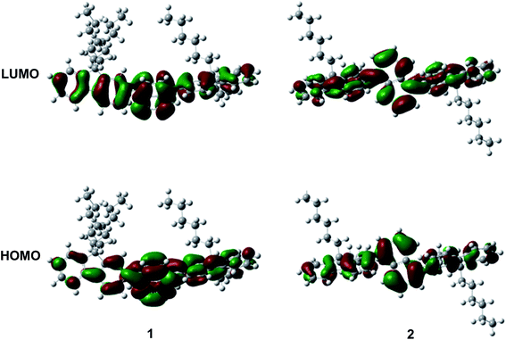
As depicted in Scheme 1, these two aromatic hydrocarbon isomers were prepared with two steps in high yields. The target emitters were obtained in very high yield (over 85%) by Suzuki coupling reaction of dibromonaphthalene with 2-(9,9-dihexyl-9H-fluoren-2-yl)-4,4,5,5-tetramethyl-1,3,2-dioxaborolane under the catalysis of Pd(PPh3)4 at 85 °C in toluene. Both two compounds are purified as white solid by column chromatography and fully characterized by mass spectra, elemental analyses and nuclear magnetic resonance (NMR) (ESI†). Two six-carbon hexyl chains were incorporated into the fluorene for improving the solubilities in the commonly used organic solvents. The NMR spectra were obtained in the solvent of chloroform-d. Due to quite similar chemical environment of proton in these compounds, the 1H NMR for 1 and 2 are not well resolved, some of them are overlapped. However, both 13C NMR spectra shows excellent resolution, although the much larger torsion angle between naphthalene and fluorene unit. In 13C NMR spectra of compounds 1 and 2, seventeen signals of aromatic carbons can be found, which can be attributed to two equivalent part of the entire molecule owing to this structural symmetry of compound 1 and 2, which is originated from the quite rapid rotation of fluorene moiety at room temperature in the solution state. Similar observation could also be found for signals from the carbons of hexyl chains, there exist seven resonances in nonaromatic region of 13C NMR spectrum for each compound. Unfortunately, crystallization of two compounds were failed due to the four flexible hexyl chains in one molecule, we optimized the molecular configuration in ground state to investigate the torsion angles between naphthalene and fluorene moiety of two compounds, as shown in Fig. S1,† torsion angles are about 54° (53.7° for 1, 54.1° for 2). Such large torsion angles indeed reduce molecular planarity to guarantee the deep-blue emission, and also effectively suppress the π–π interactions in the solid states, inducing in quite highly efficient violet to deep-blue emission. More importantly, such molecular engineering of large torsion angle reduce molecular planarity effectively, which commonly lead to the aggregation induced quenching and the red shift in emission spectrum of fluorescent materials.The photophysical property of these two compounds (1 and 2) was well investigated in both dichloromethane and film shown in Fig. 1, Tables 1, S1 and S2.† In the solution of dichloromethane, the strong absorption band in the wavelength of 228 nm and 250–350 nm is attributed to the overlap of 1π → π* transition of both naphthalene and fluorene moiety in 1 and 2.5,6 The emitters show bright deep-blue to violet fluorescent emission with a emission wavelength of 415 nm for 1 and 400 nm for 2 in the solution of CH2Cl2 (excited at 280 nm). The quartz plates were used as the substrate to record the PL spectra of the film. Under the same excitation wavelength, the emission maximum of both two emitters was slightly blue shift to 410 nm for 1 and 390 nm for 2 in the film state. The slight blue shift (about 5–10 nm) in emission maximum can be attributed to steric hindrance of four flexible hexyl chains in one molecule in solid states. More interestingly, the alternation of substituent position on naphthalene moiety can give rise to remarkable emission variation (410 nm for 1 and 390 nm for 2 in film), indicating that the substituent position has great influence on the excited state of emitters. As shown in Table S2,† the fluorescence decays are analyzed as two-exponential curves, the average emission lifetimes of these two emitters are calculated to be 0.9–2.18 ns from the two-exponential curves, supporting the fluorescent nature of emission. It should be noted that relatively large torsion angle and the hexyl chains within the fluorophors result in the weak interactions between molecules, and then hinder the π–π interactions in the solid states, inducing in the effective violet to deep-blue fluorescent emission. The electron cloud distributions of lowest unoccupied molecular orbital (LUMO) and highest occupied molecular orbital (HOMO) of 1 and 2 calculated from quantum chemical calculations were depicted in Fig. 2.7 Different from the molecule with donor–acceptor structure, the calculated electron cloud of both LUMO and HOMO distribute over nearly the whole π-conjugation skeleton of molecule, this can be explained by the fact that the electron density of naphthalene is almost the same with that of fluorene. Besides, the calculated electron cloud distributions of selected molecular orbitals of 1 and 2 are also shown in Fig. S2,† and the corresponding calculated energy levels for of 1 and 2 are listed in Table S3.† The calculated energy level gap of 1 is slightly smaller than that of 2, which is consistent with the emission energies of two compounds in the solution of CH2Cl2. The ΦPL of 1 is 0.42 in dichloromethane and 0.52 in film. The ΦPL of 2 is 0.61 in dichloromethane and 0.67 in film. The emissions exhibited narrow FWHM (52–60 nm). Moreover, in neat film, the ΦPL of two emitters is much higher than that in dichloromethane. It should also be noted that, owing to the less extent of aggregation induced quenching effect in neat film, the high ΦPL of the fluorophor could have positive influence on the performance of devices. We further investigated the electrochemical property of fluorophors by means of cyclic voltammetry (CV). As shown in Fig. S3,† the compounds show reversible oxidation wave in the solution of CH2Cl2, and the first oxidation potential of compounds was estimated to be about 1.0 V.5 The energy levels of the highest occupied molecular orbital and the lowest unoccupied molecular orbitals of compounds calculated from the CV can be calculated to be −5.80, −2.81 eV for 1 and −5.82, −2.72 eV for 2, respectively.
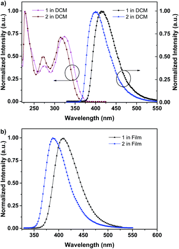 | ||
| Fig. 1 (a) UV-visible absorption (left), photoluminescence (right) spectra of 1 and 2 in CH2Cl2 at 298 K; (b) photoluminescence spectra of 1 and 2 in film at 298 K. | ||
| Compound | Emissiona | Eoxonsetb [eV] | Egc [eV] | HOMO/LUMOc [eV] | |||
|---|---|---|---|---|---|---|---|
| λem [nm] | FWHM [nm] | τ [ns] | ΦPL | ||||
| a At a concentration of 1.0 × 10⁻⁵ mol L−1 in CH2Cl2 or neat film, λex = 280 nm.b In CH2Cl2.c HOMO (eV) = −e(Eoxonset + 4.8), Eg = 1240/λ, LUMO (eV) = Eg + HOMO. | |||||||
| 1 | 415 (CH2Cl2) | 60 (CH2Cl2) | 0.90 (CH2Cl2) | 0.42 (CH2Cl2) | 1.00 | 2.99 | −5.80/−2.81 |
| 410 (film) | 57 (film) | 1.08 (film) | 0.52 (film) | ||||
| 2 | 400 (CH2Cl2) | 58 (CH2Cl2) | 0.96 (CH2Cl2) | 0.61 (CH2Cl2) | 1.02 | 3.10 | −5.82/−2.72 |
| 390 (film) | 52 (film) | 2.18 (film) | 0.67 (film) | ||||
The deep-blue fluorophor 1 was employed further to fabricate the electroluminescent device for evaluating the performance of electroluminescence. The non-doped deep-blue OLED was prepared with the device structure of indium-tin-oxide (ITO) (180 nm)/poly(3,4-ethylenedioxythiophene) doped with poly(styrenesulfonate) (PEDOT:PSS) (40 nm)/poly(9-vinylcarbazole) (PVK) (30 nm)/emitter 1 (20 nm)/2,2′,2′′-(1,3,5-benzinetriyl)-tris(1-phenyl-1-H-benzimidazole) (TPBi) (50 nm)/lithium fluoride (LiF) (1 nm)/aluminum (Al) (100 nm) as depicted in Fig. S4.† In the device, ITO is severed as the anode, and PEDOT:PSS is severed as the hole injection layer (HIL). TPBi layer and PVK layer are severed as the electron transport layer (ETL) and the hole transport layer (HTL). We use compound 1 as the non-doped light-emitting layer (EML). In order to evaluate the performance of device, a 20 nm of neat film of compound 1 was chosen. The illustration of device structure and the energy levels of involved functional materials of the deep-blue/violet device are shown in Fig. S4.† According to the energy level diagrams of device (Fig. S4b†), the LUMO/HOMO level of the fluorophor matches well with that of TPBi and PVK, proving the excellent carrier recombination within the emission layer, that is quite important for realizing a high-performance of OLED.8 The fluorophor 1-based device exhibits bright deep-blue fluorescence with narrow FWHM of 59 nm and emission maximum at 410 nm, as shown in Fig. 3a. In addition, the 1931 Commission Internationale de L'Eclairage (CIE) coordinates is located in (0.16, 0.08), which belongs to the deep-blue region (shown in Fig. 3b). Most importantly, under different working voltages from 7 V to 9 V, the normalized spectra of electroluminescence are well overlapped, indicating that the spectrum of electroluminescence cannot be affected by the working voltages, and this electrofluorescence is only emitted from the solid states of fluorophor 1.9
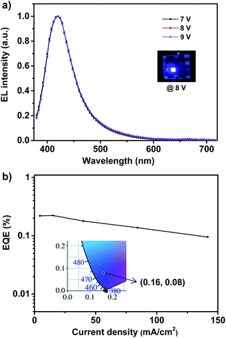 | ||
| Fig. 3 The EL spectra (a) and EQE–J curve (b) of violet/deep-blue OLED based on 1. Inset: EL photograph (up) and 1931 CIE coordinate (down) of device at 8 V. | ||
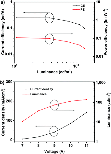
According to the EQE–current density (EQE–J) curve in Fig. 3b, current density–voltage–luminance (J–V–L) curves and current efficiency–luminance–power efficiency (CE–L–PE) curves depicted in Fig. 4, the deep-blue device based on fluorophor 1 also achieves the performance of electroluminescence. For instance, the turn-on voltages of this device is about 7 V, the highest luminance, PE, CE and EQE are 138 cd m−2, 0.11 lm W−1, 0.25 cd A−1, and 0.22%, respectively. We noted that, over the whole operation progress, the efficiency roll-off of this device is quite small. This preliminary performance of device is not high, which could be suffered from the inefficient structure of device. Nevertheless, in the aspects of the spectral properties of EL, these preliminary results imply that the compound 1 still has promising application in the deep-blue/violet devices.
3. Experimental section
3.1. Materials and reagents
All of solvents were used after distillation and stored over activated molecular sieves (5 Å). All operations were performed under an inert nitrogen atmosphere using standard Schlenk unless otherwise stated. All of chemicals and reagents were purchased from commercial sources and used without further purification.3.2. Synthesis of aromatic hydrocarbon isomers (1 and 2)
3.3. EL device fabrication and testing
The devices were fabricated on pre-patterned ITO glass substrates with a sheet resistance of 15 Ω per square. The ITO glass substrates were sequentially cleaned by the detergent, acetone, isopropyl alcohol and deionized water before use. Prior to the thin film deposition, the substrates were treated with the UV ozone to improve the work function and also to remove the possible chemical residuals left on the ITO surface during the wet cleaning processes. Poly(3,4-ethylenedioxythiophene) doped with poly(styrenesulfonate) (PEDOT:PSS) were spin-coated onto the cleaned ITO substrates at 3000 rpm for 40 s, and annealed for 20 min at 120 °C. The poly(9-vinylcarbazole) (PVK) layer was prepared by spin-coating (PVK in chlorobenzene (5 mg mL−1)) at 3000 rpm for 40 s, and annealed for 10 min at 100 °C in the glove box. The thickness of the PVK is about 20 nm. The EML layer was prepared by spin-coating (compound 1 in toluene (5 mg mL−1)) at 3000 rpm for 40 s, and annealed for 10 min at 100 °C in the glove box. The thickness of the EML is about 20 nm. Afterwards, the ITO glass substrates with PVK layer and EML layer were loaded in a vacuum chamber for deposition of organic layers using thermal evaporation under a base pressure of 5 × 10⁻⁴ Pa. The film thicknesses and the corresponding deposition rates were controlled by the calibrated crystal quartz sensors. The thickness for PEDOT:PSS/PVK/EML by spin-coating are characterized by a film step measuring instrument (Dektak-XT). Deposition rates of functional organic layers, the cathode interlayer LiF and the top Al contact were about 1 Å s−1, 0.1 Å s−1 and 3–6 Å s−1, respectively. The active emissive area of the devices is 3 mm × 3 mm, defined by the overlap between ITO anode and Al cathode.The EL spectra, CIE coordinates of OLEDs were measured using a computer controlled PR-655 spectra scan spectrometer. The J–V–L was measured by a computer-controlled Keithley 2400 source meter integrated with a BM-70A luminance meter. The CE and PE were calculated from the plot of J–V–L. The EQE was calculated from the J–V–L curve and spectra data. All samples were characterized immediately after thin films deposition without encapsulation.
3.4. Theoretical calculations
All calculations were performed using the Gaussian 09 package. The geometry optimization by density functional theory was carried out using the B3LYP functional. The 6-31G(d) basis set was used to treat all other atoms.4. Conclusion
To conclude, two novel and highly efficient deep-blue to violet fluorescent fluorene/naphthalene-based aromatic hydrocarbons were designed by connecting fluorene and naphthalene through large torsion angle. Attributed to the large torsion angle between naphthalene and fluorene unit and four hexyl chains within one molecule, the π–π interactions was largely suppressed in the solid states, giving highly efficient deep-blue to violet fluorescent emission. In neat film, bright deep-blue to violet emission at wavelength of about 410 nm with high ΦPL up to 0.67 can be observed from the designed emitters, and the full width at half maximum of emitter is relatively narrow (52 nm). In addition, the 1931 Commission Internationale de L'Eclairage coordinate and maximum emission peak for deep-blue electroluminescence based on 1 is (0.16, 0.08) and 410 nm, respectively. Further explorations of this family of deep-blue fluorescent materials for highly efficient deep-blue electroluminescence are still going on.Author contributions
P. Tao and Y. Wu conceived the experiments. Z. Gao and X. Fan made the synthesis, L. Dong, Y. Shi and T. Li performed the photophysical property measurements and analyzed the data. W. Qu performed the computational calculations. T. Yang, X. Cheng and Y. Ren fabricated the devices and analyzed the device proformance. Z. Gao, Y. Wu and P. Tao wrote the paper. All authors have given approval to the final version of the manuscript.Conflicts of interest
The authors declare no competing financial interest.Acknowledgements
The authors acknowledge National Natural Scientific Foundation of China (61905120, 61705158, 51672185), China Postdoctoral Science Foundation Funded Project (2018M640506), Natural Science Foundation of Jiangsu Province of China (BK20190740), Jiangsu Planned Projects for Postdoctoral Research Funds (2018K003B), Shanxi Province Universities Science and Technology Achievements Transformation and Cultivation Project (No. 29), Datong City Key Industry Research Project (2019014), Key Research Project of Department of Science and Technology in Henan Province (No. 192102210003) for financial support.References
- (a) P. Tao, Y. B. Zhang, J. Wang, L. W. Wei, H. X. Li, X. L. Li, Q. Zhao, X. W. Zhang, S. J. Liu, H. Wang and W. Huang, J. Mater. Chem. C, 2017, 5, 9306 RSC; (b) Y. Miao, P. Tao, L. Gao, X. Li, L. Wei, S. Liu, H. Wang, B. Xu and Q. Zhao, J. Mater. Chem. C, 2018, 6, 6656 RSC; (c) P. Tao, Y. Miao, H. Wang, B. Xu and Q. Zhao, Chem. Rec., 2019, 19, 1531 CrossRef CAS PubMed; (d) J. J. Guo, X. L. Li, H. Nie, W. W. Luo, S. F. Gan, S. M. Hu, R. R. Hu, A. J. Qin, Z. J. Zhao, S. J. Su and B. Z. Tang, Adv. Funct. Mater., 2017, 27, 1606458 CrossRef; (e) Y. Miao, K. Wang, B. Zhao, L. Gao, P. Tao, X. Liu, Y. Hao, H. Wang, B. Xu and F. Zhu, Nanophotonics, 2018, 7, 295 CAS.
- (a) J. Lee, H. Chen, T. Batagoda, C. Coburn, P. Djurovich, M. Thompson and S. Forrest, Nat. Mater., 2016, 15, 92 CrossRef CAS PubMed; (b) K. Klimes, Z. Zhu and J. Li, Adv. Funct. Mater., 2019, 29, 1903068 CrossRef; (c) X. Cai and S. Su, Adv. Funct. Mater., 2018, 28, 1802558 CrossRef; (d) Y. Miao, K. Wang, L. Gao, B. Zhao, Z. Wang, Y. Zhao, A. Zhang, H. Wang, Y. Hao and B. Xu, J. Mater. Chem. C, 2018, 6, 1853 RSC.
- (a) F. Montilla, A. Ruseckas and I. Samuel, J. Phys. Chem. C, 2018, 122, 9766 CrossRef CAS; (b) M. Bender, K. Schelkle, N. Jurgensen, S. Schmid, G. Hernandez-Sosa and U. Bunz, Macromolecules, 2016, 49, 2957 CrossRef CAS; (c) H. Wang, Y. Xu, T. Tsuboi, H. Xu, Y. Wu, Z. Zhang, Y. Miao, Y. Hao, X. Liu, B. Xu and W. Huang, Org. Electron., 2013, 14, 827 CrossRef CAS.
- L. Xie, C. Yin, W. Lai, Q. Fan and W. Huang, Prog. Polym. Sci., 2012, 37, 1192 CrossRef CAS.
- X. Feng, X. Wei, M. Yin, Y. Miao and P. Tao, Tetrahedron Lett., 2019, 60, 151340 CrossRef CAS.
- Z. Lv, L. Zou, H. Wei, S. Liu, W. Huang and Q. Zhao, ACS Appl. Mater. Interfaces, 2018, 10, 19523 CrossRef CAS PubMed.
- M. J. Frisch, G. W. Trucks, H. B. Schlegel, G. E. Scuseria, M. A. Robb, J. R. Cheeseman, G. Scalmani, V. Barone, B. Mennucci, G. A. Petersson, H. Nakatsuji, M. Caricato, X. Li, H. P. Hratchian, A. F. Izmaylov, J. Bloino, G. Zheng, J. L. Sonnenberg, M. Hada, M. Ehara, K. Toyota, R. Fukuda, J. Hasegawa, M. Ishida, T. Nakajima, Y. Honda, O. Kitao, H. Nakai, T. Vreven, J. Montgomery, J. E. Peralta, F. Ogliaro, M. Bearpark, J. J. Heyd, E. Brothers, K. N. Kudin, V. N. Staroverov, R. Kobayashi, J. Normand, K. Raghavachari, A. Rendell, J. C. Burant, S. S. Iyengar, J. Tomasi, M. Cossi, N. Rega, J. M. Millam, M. Klene, J. E. Knox, J. B. Cross, V. Bakken, C. Adamo, J. Jaramillo, R. Gomperts, R. E. Stratmann, O. Yazyev, A. J. Austin, R. Cammi, C. Pomelli, J. W. Ochterski, R. L. Martin, K. Morokuma, V. G. Zakrzewski, G. A. Voth, P. Salvador, J. J. Dannenberg, S. Dapprich, A. D. Daniels, Ö. Farkas, J. B. Foresman, J. V. Ortiz, J. Cioslowski and D. J. Fox, Gaussian09, Revision B.01, Gaussian Inc., Wallingford, CT, 2010 Search PubMed.
- (a) Y. Miao, X. Wei, L. Gao, K. Wang, B. Zhao, Z. Wang, B. Zhao, H. Wang, Y. Wu and B. Xu, Nanophotonics, 2019, 8(10), 1783 CAS; (b) X. Wei, L. Gao, Y. Miao, Y. Zhao, M. Yin, H. Wang and B. Xu, J. Mater. Chem. C, 2020, 8, 2772 RSC; (c) Y. Seino, S. Inomata, H. Sasabe, Y. Pu and J. Kido, Adv. Mater., 2016, 28, 2638 CrossRef CAS PubMed; (d) Y. Miao, K. Wang, B. Zhao, L. Gao, Y. Wang, H. Wang, B. Xu and F. Zhu, J. Mater. Chem. C, 2017, 5, 12474 RSC.
- (a) Y. Miao, K. Wang, L. Gao, B. Zhao, H. Wang, F. Zhu, B. Xu and D. Ma, J. Mater. Chem. C, 2018, 6, 8122 RSC; (b) S. Wang, M. Qiao, Z. Ye, D. Dou, M. Chen, Y. Peng, Y. Shi, X. Yang, L. Cui, J. Li, C. Li, B. Wei and W. Y. Wong, iScience, 2018, 9, 532 CrossRef CAS PubMed; (c) Y. Miao, K. Wang, L. Gao, H. Wang, F. Zhu and B. Xu, J. Mater. Chem. C, 2018, 6, 9811 RSC; (d) Y. Li, Z. Xu, X. Zhu, B. Chen, Z. Wang, B. Xiao, J. W. Y. Lam, Z. Zhao, D. Ma and B. Z. Tang, ACS Appl. Mater. Interfaces, 2019, 11, 17592 CrossRef CAS PubMed.
Footnote |
| † Electronic supplementary information (ESI) available. See DOI: 10.1039/d0ra01846e |
| This journal is © The Royal Society of Chemistry 2020 |

