 Open Access Article
Creative Commons Attribution 3.0 Unported Licence
Upconversion luminescence enhancement by Fe3+ doping in CeO2:Yb/Er nanomaterials and their application in dye-sensitized solar cells
Jingyi Bai *a,
Pingping Duana,
Xin Wanga,
Gui Hana,
Min Wangb and
Guowang Diao
 *a
*a
aSchool of Chemistry and Chemical Engineering, Yangzhou University, Yangzhou 225002, PR China. E-mail: jybai@yzu.edu.cn; gwdiao@yzu.edu.cn
bGuangling College, Yangzhou University, Yangzhou 225002, PR China
First published on 19th May 2020
Abstract
To make use of broad spectrum solar energy remains a main target in the photoelectrochemical area. Novel promising photoelectrode CeO2:Fe/Yb/Er nanomaterials supported on upconversion nanomaterials doped with transition-metal ions are reported to improve broad spectrum absorption and scattering properties in dye-sensitized solar cells (DSSCs) for the first time. The results demonstrate that the materials have stronger upconversion luminescence than CeO2:Yb/Er samples when the Fe3+ ion doping concentration is 2 mol% and 33.5% higher photoelectric conversion efficiency than a pure P25 electrode, which are attributed to the special light scattering properties and excellent dye adsorption capacity of the CeO2:Fe/Yb/Er nanomaterials. Accordingly, doping Fe3+ transition metal ions in the upconversion material CeO2:Yb/Er provides a new research idea for improving the photoelectric conversion efficiency of DSSCs.
1. Introduction
In today's deepening energy crisis, the inexhaustible solar energy has received more and more attention because of its safety, sustainability, and carbon-free nature.1 In the photovoltaic industries using solar energy, dye-sensitized solar cells are photoelectrochemical systems with dye-adsorbed porous-structured oxides as photoanodes, which have the advantages of low cost, high efficiency and good stability.2 However, the problem of spectral mismatch between the incident solar spectrum and the band gap of the semiconductor photoanode greatly reduces the utilization of sunlight by the battery. In particular, the near-infrared (NIR) light which accounts for nearly 50% of sunlight is wasted. Hence, enlarging the range of absorbable wavelengths in sunlight is one of the effective measures to reduce energy loss.3In order to obtain higher photocurrent values in the NIR region, researchers turned their attention to up-conversion materials that can convert low-energy excitations into high-energy emissions. Up-conversion nanophosphors (UCNPs) with nonlinear optical effects can convert NIR light into visible light by means of energy transfer or multiple absorptions.4 Then the dye molecule absorbs visible light and produces more electrons, which promotes the conversion of sub-band gap photons into above-band gap photons to decrease transmission loss. Consequently, it is feasible to improve battery performance by introducing UCNPs into solar cells to enhance their utilization of sunlight.5
In order to realize the above potential applications, it is particularly important to find a suitable matrix material. The semiconductor oxide material CeO2 has been widely in many fields such as photocatalysis, water oxidation, phosphors and thermoelectric materials, which is due to its environmental friendliness, thermal stability and chemical stability.6,7 Especially in this work, the similar ionic radius of Ce4+ and Yb3+, Er3+ are conducive to the doping of rare earth ions and the lower phonon energy of CeO2 is favorable for the emission of UC by reducing the multiphonon relaxation, which all lay the foundation for CeO2 as the host material.8,9 On the other hand, the remarkable features of CeO2 such as high refractive index and high optical transparency provide support for its use as a light scattering layer to increase light collection efficiency in DSSCs with double-layer photoanode.10 Herein, we have chosen CeO2 as the host material for UCNPs is reasonable, and it is also the unique innovation of our team based on the above two considerations.11 But the current exploration of CeO2-based up-conversion materials is mostly achieved by the doping between Er3+/Yb3+ and Er3+ rare earth ions, which makes it difficult to further improve the luminous intensity. Thereupon, how to overcome this problem becomes a top priority.
As we all know, the probability of electronic transition has a decisive influence on the intensity of upconversion luminescence in the UCNPs, but it is also easily affected by the local crystal field around the RE ions.12 In the sense, in addition to utilizing the plasma effect, photonic crystal effect and constructing a core–shell structure, it is a great significance to increase the UC efficiency of UCNPs by changing the symmetry of local crystal fields.13 In published literature reports, researchers have used this approach to achieve their goals. For example, the green light emission enhanced by 34 times and red light emission enhanced by 101 times when the Li+-doping concentration was 0.5 mol%, which were found in Wang's studies.14 The three-doping system with Mg2+ ions can significantly increase the red, green and purple UC emissions in UCNPs by Zhao's research.15 Compared with alkali ion doping, transition metal (TM) ions have potential to adjust the excited state properties to match the acceptor ions because the exposure of d electrons renders them very sensitive to the environment. Especially, the TM ions Fe3+ have many energy levels to enable more energy exchange with RE ions.16
The use of Fe3+ ions alone in batteries has a number of drawbacks, so we have introduced Fe3+ into DSSCs by co-doping. This paper is the first time to explore the effect of Fe3+ on the strength of UC in CeO2 matrix materials, which has important reference significance. The incorporation of non-rare earth ion Fe3+ will adjust the symmetry of the local crystal field in the materials to enhance UC luminescence intensity. The prepared materials were used as photoanodes for dye-sensitized solar cells, and the good photovoltaic performance was obtained. At the same time, a new approach has been opened for the application of Fe3+ ions in DSSCs.
2. Experiments
2.1 Preparation of CeO2:Fe/Yb/Er
0.8 g polyvinylpyrrolidone (PVP, K-30) was ultrasonically dispersed into 30 mL ultrapure water, and magnetically stirred with 60 minutes to form a clear solution. Subsequently, 2.4 mmol of metal ions [(96.7 − x) mol% Ce3+, 0.3 mol% Yb3+, 3 mol% Er3+, x mol% Fe3+ (x = 0.5, 1, 2, 3, 5)] was mixed with PVP solution and stirred vigorously for 60 minutes to make the mixture uniform. The homogenized liquid was poured into a Teflon-lined with 50 mL and hydrothermally treated at 200 °C for 12 hours. The product was centrifuged at 8000 rpm min−1 and washed several times with deionized (DI) water and ethanol, then dried overnight at 80 °C. Moreover, the precipitate was placed in a muffle furnace, heated at 400 °C for 1 hour, and then the same heating rate was controlled to continue to rise to 1100 °C and held for 3 hours. In addition, the SiO2 layer was wrapped on the surface of the materials to protect its morphology at high temperature; it was eliminated with NaOH solution (1 M) after calcination. For comparison, the CeO2:Yb/Er and CeO2:Fe nanomaterials were prepared by the same method.2.2 Fabrication of solar cells
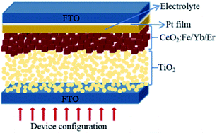
For the double layer photoanode, P25 paste was screen-printed on the FTO glasses, then the CeO2:Fe/Yb/Er nanoparticles were coated as an upper film on the basis of the TiO2 film. The double layer films with area of 0.16 cm2 were sintered at 450 °C for 30 minutes to form the photoanodes, which will be immersed in N719 dye solution (4.5 × 10⁻⁴ M in absolute acetonitrile) for 24 hours. Subsequently, rinsed photoanodes with absolute ethanol and allowed to air dry. The Pt-coated counter electrode and working electrode were assembled to form a sandwich-type battery whose structure is shown in Fig. 1. Finally, 0.5 M tert-butylpyridine, 0.1 M LiI, 0.60 M BMII and 0.05 M I2 were dissolved in an acetonitrile solution to obtain the I−/I3− electrolyte, which was dropped into the battery.17 For comparison, pure P25 electrode, CeO2:Yb/Er electrode and CeO2:Fe electrode were also assembled.2.3 Characterization
The X-ray diffraction which used the Cu-Kα radiation (λ = 1.5406) has characterized the phase purity of powder. And the overall structure was studied by scanning electron microscopy (FE-SEM) and transmission electron microscopy (TEM). High-resolution transmission electron microscopy (HR-TEM), Energy dispersive X-ray (EDX) and X-ray photoelectron spectra (XPS) have analyzed the atomic composition of the sample. The Fluorescence spectrophotometer (Shimadzu 200) measured all spectra of upconversion photoluminescence emission by using a 980 nm semiconductor laser as the excitation source, because it has steady state fluorescence. The diffuse reflectance spectra of sample were observed by a UV-vis-NIR spectrophotometer (Cary 5000). Dye desorption measurements were carried out by detaching the N719 dye from photoanode films in NaOH solution (0.1 M) and the concentration has been evaluated by UV-vis absorption spectroscopy. The I–V and the IPCE curves were valued by using a solar light simulator (Newport 94063) with the air mass 1.5 global (AM 1.5G) light. Electrochemical impedance spectroscopy (EIS) was measured in range of 100 kHz to 0.1 Hz by a computer controlled potentiostat (Autolab 320, Metrohm).3. Results and discussions
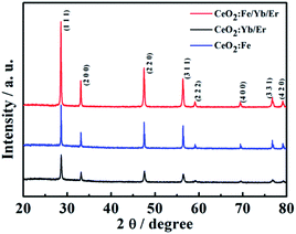
Fig. 2 shows the XRD patterns of different three nanomaterials. The characteristic diffraction peaks of all samples in the figure correspond to the (111), (200), (220), (311), (222), (400), (331) and (420) crystal planes of cubic phase CeO2 (JCPDS card no. 34-0394). And there is no other metal diffraction peaks. It can be seen that the material of CeO2:Fe/Yb/Er has the sharpest diffraction peak and the highest crystallinity, its 2θ angle that corresponding to the (111) crystal plane has shifted compared to the CeO2:Yb/Er material. This phenomenon demonstrates the successful doping of Fe3+ ions in the main system of CeO2 and the phase structure of CeO2 did not change. We can learn from the already reported literature that the doping of Fe3+ in the host lattice is achieved by replacing other ions or occupying the gap sites. What's more important, these two occupancies of Fe3+ ions in the main matrix both can change the environment around Er3+, thereby breaking the forbidden band transition and facilitating the f–f intra-configuration transition of rare earth ions.18SEM and TEM images characterize the morphologies of the prepared samples. As shown in Fig. 3a and d, the CeO2:Yb/Er sample with a particle diameter of 800 nm is composed of octahedral porous structures. Fig. 3b inset displays the HRTEM image of the sample and clearly shows that the nanoparticles are formed by agglomeration of small nanoparticles with a particle size of 3–5 nm. When the Fe3+ ions are introduced, the samples of CeO2:Fe/Yb/Er (Fig. 3b and e) and CeO2:Fe (Fig. 3c and f) are not only well dispersed but also uniform in size, their particle size was shrunk to about 120 nm. From the comparison of the three samples, it is observed that the doping of Er3+ and Yb3+ ions have no effect on the morphology of materials, but the Fe3+ doping has obviously influenced the particle size of samples.
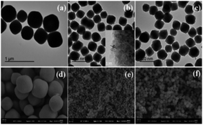 | ||
| Fig. 3 TEM images of (a) CeO2:Yb/Er; (b) CeO2:Fe/Yb/Er; (c) CeO2:Fe and SEM images of (d) CeO2:Yb/Er; (e) CeO2:Fe/Yb/Er; (f) CeO2:Fe. | ||
It can be deduced that the ionic radius of Er3+ (0.89 Å) and Yb3+ (0.868 Å) have little difference with the Ce4+ (0.87 Å), whereas Fe3+ (0.64 Å) with much smaller ionic radius than Ce4+ (0.87 Å), which induce to hinder the growth of the crystal.9
Fig. 4 specifically shows the structural details of the CeO2:Fe/Yb/Er crystal. The EDX spectrum (Fig. 4a) confirms the successful doping of Er3+, Yb3+ and Fe3+ ions in samples.
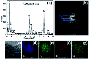 | ||
| Fig. 4 (a) EDX spectrum; (b) SAED pattern; (c) HRTEM image and (d–g) elemental mapping of the CeO2:Fe/Yb/Er nanomaterials. | ||
The elemental mappings in Fig. 4d–g further prove the uniform distribution of Ce, Fe, Yb and Er in the whole nanoparticles. The SAED pattern (Fig. 4b) and HRTEM image (Fig. 4c) display the intercrystalline diffraction rings of CeO2:Fe/Yb/Er UCNPs and a typical 0.271 nm lattice spacing attributed to the (111) crystal plane of CeO2.
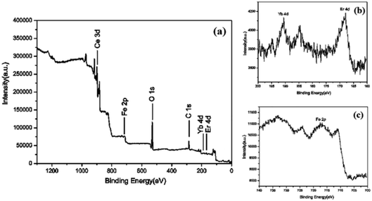
The surface elemental composition and chemical states of CeO2:Fe/Yb/Er is analyzed by XPS. It can be know from the XPS survey spectrum (Fig. 5a) that the CeO2:Fe/Yb/Er UCNPs only contains several elements of Ce, O, Fe, Er and Yb. The core level XPS spectrum of Ce 3d is attributed to the signal binding energies of Ce4+ state while some of Ce3+ state, the binding energy peak at 902.4 eV is attributed to high concentration of Ce3+ and the binding energy peaks at 919.3, 900.3 eV are attributed to Ce4+ oxidation state.
As shown in Fig. 5b, the Yb 4d and Er 4d XPS peaks were observed at a lower binding energy position at 192.3 eV and 168.4 eV, respectively.19–21 XPS signals of Fe 2p (Fig. 5c) at 711 eV can be assigned to Fe 2p3/2 and Fe 2p1/2. The major peak at 530.0 eV corresponds to O2 and another two shoulder peaks around the main peak at 530 eV may correspond to be oxygen adsorbed water and forming hydroxyl groups. XPS proved the presence of Fe3+, Yb3+, Er3+, Ce4+ and Ce3+ ions in the samples.
When the amount of Yb3+ and Er3+ is constant, Fig. 6a shows the UC luminescence spectra of CeO2:Fe/Yb/Er UCNPs with Fe3+-doping concentration from 0.5% to 5% at room temperature under the commercial continuous wave diode 980 nm laser. The upconversion emission intensities were changed with the Fe3+ doping. Two green emissions ranging from 517 to 532 nm and from 532 to 551 nm were deduced from the 2H11/2 → 4I15/2 and 4S3/2 → 4I15/2 transitions respectively. The red emission is observed at 659 nm and 679 nm, which due to the 4F9/2 → 4I15/2 transition of Er3+.22 It can be known that the intensity of the upconversion photoluminescence changes significantly with the increase of the Fe3+ ion concentration, and the luminescence intensity is the strongest at the Fe3+-doping concentration of 2 mol%. While the enhancement rate of green light is obviously higher than the red region (Fig. 6b). It can also be observed from the fluorescence spectra of the three materials in Fig. 6c that doping Fe3+ does not affect the peak position. Furthermore, the green and red emission of CeO2:Fe/Yb/Er (CFe = 2 mol%) samples are nearly 7 and 3 times stronger than those of CeO2:Yb/Er materials, respectively. But the CeO2:Fe samples without doped rare earth ions have no luminescent effect. This phenomenon is probably due to the fact that the Fe3+ ions with a smaller ion radius in the lattice shorten the average bond lengths of O–Ln bond, which destroys the symmetry of local crystal field around the RE ions and increases the probability of electric dipole transition, therefore the upconversion luminous intensity is obviously enhanced. But the higher concentration of Fe3+ may induces severe distortion of the crystal lattice, which will affects the spatial distribution of Er3+ ions and cause concentration quenching, which eventually induced the fluorescence radiation decreased.12,23 Possible reason is there may be Yb3+–Fe3+ dimer complex formation in the Yb3+–Er3+–Fe3+ tridoped system. The mixed electron wave functions of 3d5 electron-exposed Fe3+ ions and Yb3+ ions formed some new energy levels, thus triggering new energy transfer and enhancing UC emission.18,21
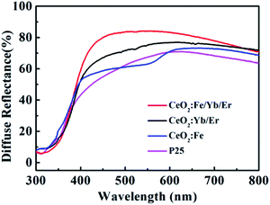
The UV diffuses reflectance spectra of four samples (Fig. 7) display that the changes after doping with Fe3+ ions are clearly related to the characteristics of unsensitized photoanodes. The reflectance characteristics of the CeO2:Fe/Yb/Er increase distinctly compared with other materials. Furthermore, the CeO2:Fe/Yb/Er electrode shows the highest reflectance within the long wavelength region (550–800 nm). When sunlight is irradiated onto DSSCs, the NIR photons can be converted into visible photon by the CeO2:Fe/Yb/Er nanomaterial layers. It is indicated that the upconversion luminescent materials can be used as an excellent light scattering medium for expanding the optical path length in the electrode, which will improve its light capturing ability and photoelectric conversion efficiency. It is worth mentioning that the electrode coated with CeO2:Fe materials has no advantage in light scattering because of its no upconversion characteristics.24
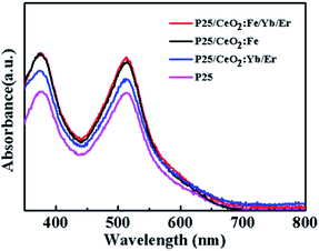
As we all know, the dye loading capacity of the photoanode films will greatly affect the efficiency of the DSSCs. Fig. 8 is an absorption spectrum of N719 dye in a 0.1 M NaOH solution. Obviously, the photoanodes after printed materials have a significant improvement in dye adsorption compared to the pure P25 electrode. Among them, the films of CeO2:Fe/Yb/Er and CeO2:Fe have the same dye adsorption capacity substantially, and both are larger than CeO2:Yb/Er film. This may be attributed to the smaller particle diameter of CeO2:Fe/Yb/Er and CeO2:Fe nanomaterials than the CeO2:Yb/Er and the enhancement of the ability in dyes adsorbing.
The top and cross-section of the photoanode were characterized by SEM images. Fig. 9a shows that the photoanode of DSSCs is a typical two-layer structure, and its light scattering materials is tightly covered on the host material TiO2. The two layers fused to form a large assembly and the boundary is clearly visible. As can be seen in Fig. 9b, the upconversion nanomaterials are adhered to each other and are uniformly arranged on the P25 layer with the help of adhesives which is consisted of ethylcellulose and Triton X-100 terpineol solution.25
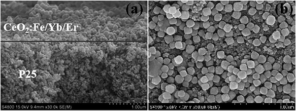 | ||
| Fig. 9 (a) SEM images of cross-section of the bilayer photoelectrode; (b) the surface for CeO2:Fe/Yb/Er and P25 layer. | ||
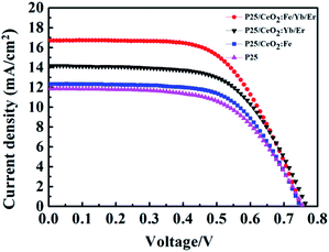
The DSSCs coated with different materials have been tested for I–V (Fig. 10) and the photovoltaic parameters are shown in Table 1. After coating CeO2:Fe material on the P25 film, the short-circuit current is improved from 11.85 mA cm−2 which only had the TiO2 film up to the 12.32 mA cm−2 and the photoelectric conversion efficiency increased form 5.47% to 5.89%. When a layer of CeO2:Yb/Er up-conversion material was added to the P25 layer, Jes and η were further raised to 14.17 mA cm−2 and 6.74%, respectively. Here, the enhancement of efficiency may rely on the broadened range of absorbable spectrum, and making fuller use of near-infrared light in sunlight. What is more important, a high conversion efficiency of 7.30% and a short-circuit current of 16.70 mA cm−2 were achieved because the introduction of the composite material CeO2:Fe/Yb/Er on the TiO2 film as a light scattering layer. The enhancement of 33.5% than the pure P25 electrode in efficiency was directly ascribed to the dye loading capacity, light capture ability and upconversion effect of CeO2:Fe/Yb/Er UCNPs. Especially its stronger upconversion luminescence intensity makes the battery efficiency enhanced by 8.3% compared with the CeO2:Yb/Er electrode. Note that its battery efficiency is 23.9% higher than the CeO2:Fe battery can be further seen that the upconversion effect plays a vital role in DSSCs.
| Jsc (mA cm−2) | Voc (V) | FF | η (%) | |
|---|---|---|---|---|
| CeO2:Fe/Yb/Er | 16.704 | 0.744 | 0.610 | 7.30 |
| CeO2:Yb/Er | 14.167 | 0.763 | 0.613 | 6.74 |
| CeO2:Fe | 12.323 | 0.744 | 0.631 | 5.89 |
| P25 | 11.852 | 0.753 | 0.603 | 5.47 |
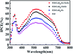
The IPCE spectrum of batteries is detailed in Fig. 11. In a certain wavelength range, the light capture ability of all photoanodes improved compared to the P25 electrode with the lowest IPCE value. It is attributed that the stronger dye absorption capacity on the particles surface will generate more photoelectrons to remarkably improve the photoelectric conversion efficiency. In addition, the UC luminescence effect is believed to enhance the light-trapping ability of the electrodes by enhancing the optical density. Herein, the CeO2:Fe/Yb/Er layer obtains the highest IPCE value because of its stronger up-conversion luminescence intensity. The measurement result of IPCE is consistent with I–V and UV tests.
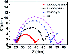
In order to investigate the transmission and recombination of photo-generated electrons in DSSCs, the electrochemical impedance measurements of solar cells with four different photoanodes were performed under the condition that the light intensity is 100 mW cm−2 and the scanning frequency ranges from 100 kHz to 0.1 Hz, the result is shown in Fig. 12. The middle large semicircle is ascribed to the recombination resistance and chemical capacitance across the photoanode/dye/electrolyte interface. The CeO2:Fe/Yb/Er electrode doped with Fe3+ ions obtains the lowest electronic recombination resistance with a value of 12.5 Ω. This incident confirmed that the increase number of dye molecules and the improvement of light utilization can reduce the impedance at the intermediate frequency, thereby increasing the amount of photo-generated electrons. Thus the purpose of heighten the photoelectric conversion efficiency of DSSCs can be achieved.
4. Conclusions
In conclusion, the CeO2:Fe/Yb/Er nanomaterials with uniform size were perfectly prepared by a hydrothermal method. To guarantee the upconversion luminescent intensity, the Fe3+ ions were introduced in materials to enhance the intensity by changing the symmetry of the local crystal field around the Er3+ ions. At the meanwhile, the behavior of incorporation Fe3+ ions into the host material improves the light scattering ability of this material. And it also enables materials to gain better dye loading capacity because the smaller ionic radius of Fe3+ shrank the lattice ruler will obtain a larger specific surface area. Additionally, the photoelectric conversion efficiency of solar cells using CeO2:Fe/Yb/Er UCNPs as the light scattering layer can reach 7.30%, which is 33.5% higher than the pure P25 electrodes. And its process of improving the photovoltaic performance of dye-sensitized cells is mainly accomplished by expanding the spectral absorption range and making fuller utilization of sunlight. This illustrates the great possibility and feasibility of the abundant Fe3+ ions on the earth applied to DSSCs. Furthermore, some explorations in this work that related to the use of transition metal ion Fe3+ to enhance up-conversion luminescence provide a novel idea for the improvement of upconversion materials widely used in scientific research.Conflicts of interest
There are no conflicts to declare.Acknowledgements
This work was supported by the National Natural Science Foundation of China (grant 20973151, 20901065, 21273195 and 21671169), and Project Funded by the Priority Academic Program Development of Jiangsu Higher Education Institutions. The authors also acknowledge the Testing Center of Yangzhou University for EDS and HRTEM measurements.References
- J. M. Ji, H. Zhou and H. K. Kim, Rational design criteria for D-pi-A structured organic and porphyrin sensitizers for highly efficient dye-sensitized solar cells, J. Mater. Chem. A, 2018, 6(30), 14518–14545 RSC.
- V. Kumar, A. Pandey, S. K. Swami, O. M. Ntwaeaborwa, H. C. Swart and V. Dutta, Synthesis and characterization of Er3+-Yb3+ doped ZnO upconversion nanoparticles for solar cell application, J. Alloys Compd., 2018, 766, 429–435 CrossRef CAS.
- T. Chen, S. W. Hao, A. Azimbay, Y. F. Shang, Q. L. Pi, Y. D. Hou and C. H. Yang, Optimizing concurrent extension of near-infrared and ultraviolet light harvesting of dye sensitized solar cells by introducing sandwich-nanostructured upconversion-core/inert-shell/downconversion-shell nanoparticles, J. Power Sources, 2019, 430, 43–50 CrossRef CAS.
- J. Dutta, V. K. Rai, M. M. Durai and R. Thangavel, Development of Y2O3:Ho3+/Yb3+ Upconverting Nanophosphors for Enhancing Solar Cell Efficiency of Dye-Sensitized Solar Cells, IEEE J. Photovolt., 2019, 9(4), 1040–1045 Search PubMed.
- P. Du, J. H. Lim, J. W. Leem, S. M. Cha and J. S. Yu, Enhanced Photovoltaic Performance of Dye-Sensitized Solar Cells by Efficient Near-Infrared Sunlight Harvesting using Upconverting Y2O3:Er3+/Yb3+ Phosphor Nanoparticles, Nanoscale Res. Lett., 2015, 10, 321–327 CrossRef PubMed.
- Z. D. Wang, X. Z. Li, H. M. Qian, S. X. Zuo, X. Y. Yan, Q. Chen and C. Yao, Upconversion Tm3+:CeO2/palygorskite as direct Z-scheme heterostructure for photocatalytic degradation of bisphenol A, J. Photochem. Photobiol., A, 2019, 372, 42–48 CrossRef CAS.
- X. Z. Li, H. G. Zhang, H. H. Lu, S. X. Zuo, Y. Y. Zhang and C. Yao, Photo-assisted SCR removal of NO by upconversion CeO2/Pr3+/attapulgite nanocatalyst, Environ. Sci. Pollut. Res., 2019, 26(13), 12842–12850 CrossRef CAS PubMed.
- D. M. Han, Y. Yang, F. B. Gu and Z. H. Wang, Tuning the morphology and upconversion fluorescence of CeO2:Er/Yb nano-octahedra, J. Alloys Compd., 2016, 656, 524–529 CrossRef CAS.
- L. Baca, H. Steiner and N. Stelzer, Upconversion luminescence and optical thermometry in Er3+/Yb3+ co-doped CeO2 for space application, J. Alloys Compd., 2019, 774, 418–424 CrossRef CAS.
- L. G. A. Carvalho, L. A. Rocha, J. M. M. Buarque, R. R. Goncalves, C. S. Nascimento, M. A. Schiavon, S. J. L. Ribeiro and J. L. Ferrari, Color tunability in green, red and infra-red upconversion emission in Tm3+/Yb3+/Ho3+ co-doped CeO2 with potential application for improvement of efficiency in solar cells, J. Lumin., 2015, 159, 223–228 CrossRef CAS.
- A. Corma, P. Atienzar, H. Garcia and J. Y. Chane-Ching, Hierarchically mesostructured doped CeO2 with potential for solar-cell use, Nat. Mater., 2004, 3(6), 394–397 CrossRef CAS PubMed.
- P. Ramasamy, P. Chandra, S. W. Rhee and J. Kim, Enhanced upconversion luminescence in NaGdF4:Yb, Er nanocrystals by Fe3+ doping and their application in bioimaging, Nanoscale, 2013, 5(18), 8711–8717 RSC.
- Z. Yin, H. Li, W. Xu, S. B. Cui, D. L. Zhou, X. Chen, Y. S. Zhu, G. S. Qin and H. W. Song, Local Field Modulation Induced Three-Order Upconversion Enhancement: Combining Surface Plasmon Effect and Photonic Crystal Effect, Adv. Mater., 2016, 28(13), 2518 CrossRef CAS PubMed.
- X. W. Wang, X. Zhang, Y. B. Wang, H. Y. Li, J. Xie, T. Wei, Q. W. Huang, X. J. Xie, L. Huang and W. Huang, Comprehensive studies of the Li+ effect on NaYF4:Yb/Er nanocrystals: morphology, structure, and upconversion luminescence, Dalton Trans., 2017, 46(28), 8968–8974 RSC.
- S. W. Zhao, W. Liu, X. Y. Xue, Y. S. Yang, Z. Y. Zhao, Y. F. Wang and B. Zhou, Enhanced upconversion luminescence and modulated paramagnetic performance in NaGdF4:Yb, Er by Mg2+ tridoping, RSC Adv., 2016, 6(107), 105270–105271 RSC.
- W. Wei, J. Q. Jiao, Y. Liu, L. H. Liu, B. Z. Lv, Z. H. Li, S. S. Gai and J. G. Tang, Effect of the Fe3+ concentration on the upconversion luminescence in NaGdF4:Yb3+, Er3+ nanorods prepared by a hydrothermal method, J. Mater. Sci., 2019, 54(20), 13200–13207 CrossRef CAS.
- Z. S. Wang, H. Kawauchi, T. Kashima and H. Arakawa, Significant influence of TiO2 photoelectrode morphology on the energy conversion efficiency of N719 dye-sensitized solar cell, Coord. Chem. Rev., 2004, 248(13–14), 1381–1389 CrossRef CAS.
- J. Tang, L. Chen, J. Li, Z. Wang, J. H. Zhang, L. G. Zhang, Y. S. Luo and X. J. Wang, Selectively enhanced red upconversion luminescence and phase/size manipulation via Fe3+ doping in NaYF4:Yb, Er nanocrystals, Nanoscale, 2015, 7(35), 14752–14759 RSC.
- Y. J. Li, L. Yao, D. K. Xu, Y. L. Hu, S. H. Yang and Y. L. Zhang, Enhanced UV-Vis-NIR activated photocatalytic activity from Fe3+-doped BiOBr:Yb3+/Er3+ upconversion nanoplates: synergistic effect and mechanism insight, Inorg. Chem. Front., 2019, 6(1), 126–136 RSC.
- J. Y. Bai, X. L. Sun, G. Han and G. W. Diao, Double-shell CeO2@TiO2 hollow spheres composites with enhanced light harvesting and electron transfer in dye-sensitized solar cells, J. Alloys Compd., 2017, 722, 864–871 CrossRef CAS.
- Y. T. Zhang, Y. L. Shen, M. Liu, Y. Han, X. L. Mo, R. B. Jiang, Z. B. Lei, Z. H. Liu, F. Shi and W. P. Qin, Enhanced high-order ultraviolet upconversion luminescence in sub-20 nm beta-NaYbF4:0.5% Tm nanoparticles via Fe3+ doping, Crystengcomm, 2017, 19(9), 1304–1310 RSC.
- C. Homann, L. Krukewitt, F. Frenzel, B. Grauel, C. Wurth, U. Resch-Genger and M. Haase, NaYF4:Yb,Er/NaYF4 Core/Shell Nanocrystals with High Upconversion Luminescence Quantum Yield, Angew. Chem. Int. Ed., 2018, 57(28), 8765–8769 CrossRef CAS PubMed.
- Y. H. Hu, X. H. Liang, Y. B. Wang, E. Z. Liu, X. Y. Hu and J. Fan, Enhancement of the red upconversion luminescence in NaYF4:Yb3+, Er3+ nanoparticles by the transition metal ions doping, Ceram. Int., 2015, 41(10), 14545–14553 CrossRef CAS.
- G. Han, M. Wang, D. Y. Li, J. Y. Bai and G. W. Diao, Novel upconversion Er, Yb-CeO2 hollow spheres as scattering layer materials for efficient dye-sensitized solar cells, Sol. Energy Mater. Sol. Cells, 2017, 160, 54–59 CrossRef CAS.
- J. Y. Bai, R. F. Zhao, G. Han, Z. C. Li and G. W. Diao, Synthesis of 1D upconversion CeO2:Er, Yb nanofibers via electrospinning and their performance in dye-sensitized solar cells, RSC Adv., 2015, 5(54), 43328–43333 RSC.
| This journal is © The Royal Society of Chemistry 2020 |

