 Open Access Article
Creative Commons Attribution 3.0 Unported Licence
3D flower-like molybdenum disulfide modified graphite felt as a positive material for vanadium redox flow batteries†
Lei Wanga,
Shuangyu Lia,
Dan Lib,
Qinhao Xiaoa and
Wenheng Jing *a
*a
aState Key Laboratory of Materials-Oriented Chemical Engineering, College of Chemical Engineering, Nanjing Tech University, Nanjing 211816, China. E-mail: jingwh@njtech.edu.cn
bJiangsu Jiayi Thermal Power Co., Ltd., Changzhou 213200, China
First published on 4th May 2020
Abstract
3D flower-like molybdenum disulfide microsphere modified graphite felt (MoS2/GF) with excellent electrocatalytic activity and redox reversibility for the VO2+/VO2+ couple is successfully fabricated by a facile hydrothermal method. The results show that the hydrothermal reaction time has a deep influence on the MoS2 structure; an open 3D flower-like MoS2 structure with a layer spacing of 0.63 nm is uniformly grafted on the GF surface for a reaction time of 36 h. With the presence of MoS2, the total resistance (1.58 Ω) and charge transfer resistance (0.01 Ω) of MoS2/GF-36 are smaller than that of the heat treated GF (2.04 Ω and 11.27 Ω, respectively), indicating that the electrode has better conductivity and more favorable electron transfer ability. As expected, a significant increase in the capacity and energy efficiency is obtained with the MoS2/GF-36 electrode. These satisfactory results are attributed to the 3D flower-like structure on the surface of the electrode, which increases the contact area between the electrode and the electrolyte. More importantly, the MoS2/GF electrode with excellent stability has great application prospect in vanadium redox flow batteries (VRFBs).
1. Introduction
As global environmental pollution and energy shortages caused by the use of fossil fuels become increasingly prominent, the global strategic deployment of clean energy, such as solar energy and wind energy, has been accelerating.1–3 However, due to the unstable and intermittent nature of clean energy, the deployment of large-scale energy storage systems (ESSs) is in high demand. Among different ESSs, redox flow batteries (RFBs) are considered to be one of the most promising technologies because of their attractive features, including their high energy efficiency, long cycle life, safety and stability.4–6 The researchers found many types of batteries, such as Ce–V, Cr–Fe, Ce–Ce, V–V, etc.7–9 Among them, the all-vanadium redox flow battery (VRFB) has received considerable attention and is at the commercial demonstration stage, which employs the same elements in two semi-batteries, decreasing the risk of the cross-contamination of the electrolyte.10A VRFB mainly consists of three components, including the electrolyte, the separation membrane and the electrode. The redox reaction performs on the surface of the electrode; thus a high activity electrode is desirable for improving the power density and energy density of a VRFB. It has demonstrated that the redox reaction (V2+/V3+) at the negative electrode is reversible and present fast reaction kinetics due to having only one electron transfer. By contrast, the positive reaction is more complex (one electron and two protons are transferred) and presents relatively slow reaction kinetics, so the reaction at the positive electrode (VO2+/VO2+) is the rate determination step.11–14 In addition, the range of the electrocatalytic materials is limited by the acidic medium and the high redox potential (1.0 V) of the VO2+/VO2+ couple.15,16 Therefore, it is critically important to develop a high activity and stable electrode, especially the positive electrode, to enhance the battery's performance.
Currently, polyacrylonitrile (PAN) graphite felt (GF) is widely used as a VRFB electrode due to its good stability in strong acid solutions, wide operating potential range, high conductivity and high surface area.17,18 In spite of these merits, GFs commonly require further functionalization treatments for fast reaction kinetics and better wettability. As a result, various surface treatments have been made to improve the electrochemical activity of the electrode by increasing the oxygen functional groups or nitrogen functional groups, such as thermal treatment, acid treatment, ammonia treatment or depositing catalysts onto the surface of electrode.19–28 Among those, intensive efforts have been focused on depositing catalysts onto the surface of the electrode due to the flexibility in adjusting the catalytic activity and surface morphology. Recently, MoS2 nanosheets, which have a typical graphite-like layered structure, have received significant attention and are considered to be a promising anode material due to their high electrocatalytic activity and large interlayer spacing (0.62 nm). It has been demonstrated that grafting MoS2 onto carbon fiber can enhance the electron transfer and increase their available and accessible active surface area.29,30 Nevertheless, the low inherent electronic conductivity of MoS2 would cause serious polarization and a low electrode utilization efficiency. In this regard, tailoring and optimizing the nanostructure of MoS2 are necessary in order to achieve a high electrochemical performance. For instance, flower-like MoS2/C nanospheres in an Na-ion battery anode present a high capacity and long cycle life.31 Additionally, increasing the layer spacing would reduce the ion diffusion resistance. Therefore, to be applied in VFRBs, the nanostructure of MoS2 should be elaborately designed to obtain a high battery efficiency.
In this study, we successfully synthesized low-cost 3D flower-like MoS2 as an electrocatalyst on the surface of GF to enhance the electrochemical activity of the VO2+/VO2+ redox reaction via a facile hydrothermal method. It has been reported that the hydrothermal reaction time plays an important role in controlling the MoS2, so the influence of the reaction time on the structure and electrode performance was carefully investigated.32,33 For applications in the VRFB as an anode, the vanadium species reaction activity, the diffusion coefficient and the performance of a single VRFB cell were systematically studied to provide us with an insight into the effect of the MoS2 structure on the electrochemical performance.
2. Experimental procedures
2.1 Electrode preparation
All commercially available chemicals for this experiment were analytical grade and used directly without further purification. To avoid impurities and enhance wettability, commercial GFs (Shanghai Hongsheng Industrial Co., Ltd.) were sonicated in ethanol for 30 min, washed with deionized water and dried at 80 °C. Finally, the GFs were calcined in a muffle furnace at 400 °C for 2 h and marked as H-GFs.For the preparation of the molybdenum disulfide doped graphite felt (MoS2/GF) electrodes, 0.48 g of Na2MoO4·2H2O and 0.6 g of thiourea (CH4N2S) were dissolved into 60 mL of deionized water under strong stirring. Then the H-GFs were infiltrated into the prepared solution and reacted at 200 °C for 24, 36 and 48 h in a 100 mL Teflon-line stainless-steel autoclave, denoted as MoS2/GF-X (X = 24, 36, 48). After cooling down, the electrodes were washed with a large amount of deionized water and ethanol, and dried at 80 °C.
2.2 Physicochemical characterization
The surface morphology and elemental mapping studies of the obtained electrodes were investigated via a scanning electron microscopy (SEM) and an energy dispersive X-ray spectroscopy (EDX) (Hitachi S-4800 microscope, Japan). A transmission electron microscope (TEM) and high-resolution transmission electron microscopy (HRTEM) images were obtained using a TF20, Jeol 2100F microscope. X-ray diffraction (XRD) measurements were performed on a Japanese science X-ray diffractometer (Miniflex 600X) with a Cu Kα radiation source (λ = 1.5418 Å), scanning between 5° and 80° (2θ) at a scan rate of 15° min−1. The Raman spectrum was recorded on a LabRAM HR Raman microscope. The X-ray photoelectron spectroscopy (XPS) analyses were performed with a ThermoFisher ESCALAB 250XiXPS system.2.3 Electrochemical measurements
Cyclic voltammetry (CV) and electrochemical impedance spectroscopy (EIS) were performed on a GAMRY Reference 3000 electrochemical workstation using a three-electrode configuration in a 0.1 M VOSO4·3H2O and 3 M H2SO4 solution, which consisted of a MoS2/GF-X as the working electrode (1 cm × 1 cm), a platinum sheet as the counter electrode, and a saturated calomel electrode (SCE) as the reference electrode. The CV test was conducted from 0 to 1.6 V vs. the SCE at scan rates ranging from 1–30 mV s−1. The EIS test was conducted under an open circuit potential (OCP) with an excitation signal of 10 mV in the frequency range from 105 to 10−2 Hz. For comparison, the H-GF was also studied and all the electrochemical characterizations were performed at room temperature in an N2 atmosphere.2.4 VRFB single cell test
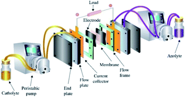
The structure of the VRFB is shown in Fig. 1, and mainly consists of electrolytes, electrodes, various plates, ion exchange membrane, tanks and pumps. Among those, MoS2/GF-36 (3 cm × 3.5 cm) was employed as the positive electrode, while H-GF was used as the negative electrode. A Nafion 117 (real working area is 3 cm × 3.5 cm, DuPont, USA) membrane was utilized as the separator. The electrolyte consisted of 1.5 M VOSO4·3H2O and 3 M H2SO4 with a volume of 15 mL. The cell test was performed on a BTS-5V6A battery testing system (Shenzhen Newware Technology Electronics Co., Ltd.) with a potential range of 0.75–1.75 V. The charge–discharge test was conducted at current densities ranging from 30 to 150 mA cm−2. For comparison, a VRFB with H-GF as the positive electrode was also studied. Furthermore, all the VRFB cell tests were performed at room temperature in an N2 atmosphere.3. Result and discussion
3.1 Physicochemical characterization
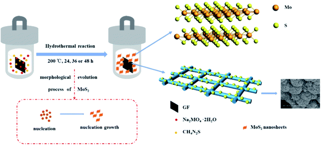
3D flower-like molybdenum disulfide modified graphite felt (MoS2/GF) was directly fabricated via a simple one-step hydrothermal method, for which the schematic illustration is shown in Fig. 2. During the reaction process, thiourea is hydrolyzed to H2S, NH3 and CO2, and H2S is further hydrolyzed to H+ and S2− under the high temperature and pressure environment. Then, Mo6+ is reduced by the presence of H+ and the precipitate particle of MoS2 is formed. The detailed reaction process is expressed by eqn (1)–(3). To further form the MoS2 microspheres, the particle mainly experiences a three-stage process, including rapid nucleation, orientation aggregation of nanosheets and the self-assembly of microsphere structures.34 In this case, the molar ratio of Na2MoO4·2H2O to CSN2H4 is 1![[thin space (1/6-em)]](https://www.rsc.org/images/entities/char_2009.gif) :
:![[thin space (1/6-em)]](https://www.rsc.org/images/entities/char_2009.gif) 4, a large amount of MoS2 nuclei is formed in the first phase, and then the MoS2 nuclei develop to nanosheets because of the different growth rates of the crystal faces. Subsequently, to reduce their surface energy, the MoS2 nanosheets gather together and wrap around to form flower-like microspheres.
4, a large amount of MoS2 nuclei is formed in the first phase, and then the MoS2 nuclei develop to nanosheets because of the different growth rates of the crystal faces. Subsequently, to reduce their surface energy, the MoS2 nanosheets gather together and wrap around to form flower-like microspheres.| CS(NH2)2 + 2H2O → CO2 + 2NH3 + H2S | (1) |
| H2S → 2H+ + S2− | (2) |
| 4MoO42− + 9S2− + 24H+ → 4MoS2 + SO42− + 12H2O | (3) |
To verify this, the surface morphology of the H-GF and MoS2/GF-X electrodes are detected with the results shown in Fig. 3. As observed, H-GF presents a typical interconnected network structure and its surface is defect-free and smooth. For the MoS2/GF-24 electrode, the surface of the GF is covered by a large number of MoS2 nanosheets. However, the nanosheets do not have an adequately developed flower structure. As the reaction time is extended to 36 h, uniform and dense MoS2 flower-like microspheres with diameters of ∼1 μm are observed on the GF surface, and the microsphere consists of tens of nanosheets from the high-magnification SEM image (Fig. 3(h)), which favors the adsorption and transfer of vanadium ions. However, the MoS2 nanosheets are non uniformly dispersed on the surface of the GF; most of the GF fibers cover many layers of MoS2 nanosheets and the 3D flower-like MoS2 spheres disappear when the reaction time is further extended to 48 h. The possible reason is that the accumulation of the H+ with the reaction time causes the charge shielding effect that a large amount of H+ gather on the edge of the nanosheet, resulting in MoO42− and S2− only reacting with the outer layer of H+ to form MoS2. Therefore, the growth of the MoS2 nanosheets is inhibited to some extent, and finally leads to the disappearance of the petals. Based on this result, it is not difficult to determine that the optimum reaction time for obtaining 3D flower-like spheres on the surface of the GF is 36 h.
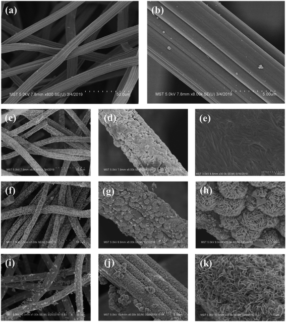 | ||
| Fig. 3 SEM images of (a and b) H-GF, (c–e) MoS2/GF-24, (f–h) MoS2/GF-36 and (i–k) MoS2/GF-48 electrodes. | ||
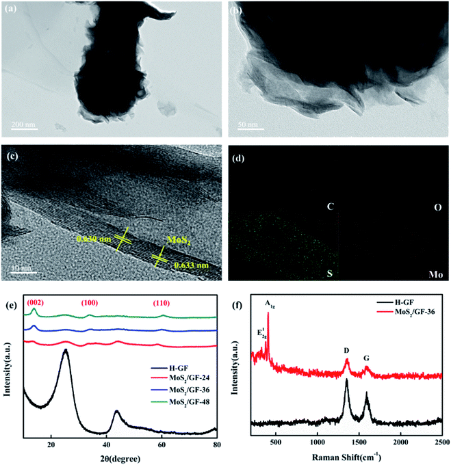
Thereafter, the structure of MoS2/GF-36 is further analyzed via TEM and HRTEM, the results of which are shown in Fig. 4(a)–(c). It can be seen from the images that the MoS2 on the GF present a typical layered structure with an interlayer distance of 0.63 nm, corresponding to the (002) planes of MoS2.35 This layered structure can increase the available and accessible active surface area to electrolyte and enhance the redox reaction of the vanadium ions. Moreover, the MoS2/GF-36 consists of four elements, including Mo, S, O and C according to the EDX elemental spectra, wherein the four elements are evenly distributed on the GF surface (Fig. 4(d)).
The crystal structure of the H-GF and MoS2/GF-X electrodes are investigated by their XRD patterns (Fig. 4(e)). For the H-GF electrode, two peaks at 25.1° and 43.2° are observed, corresponding to the (002) and (100) planes of the GF, respectively.36 In the presence of the MoS2, new characteristic peaks at 13°, 33° and 59° appear, respectively corresponding to the (002), (100) and (110) crystal planes of MoS2, indicating the synthesized MoS2 presents a hexagonal crystal structure.37 Furthermore, the crystallinity of MoS2 is enhanced with an increase in the reaction time. It is worth noting that the diffraction peaks of the (100) and (110) crystal planes of the MoS2/GF-36 electrode are not obvious, and the diffraction peaks of the (002) crystal plane become obvious, indicating that the MoS2 nanosheets of the MoS2/GF-36 electrode are relatively thin and have more exposed edge structures. Further evidence for MoS2 grafting on the GF surface is provided by the Raman spectra (Fig. 4(f)). The GF present two different peaks at 1350 cm−1 and 1592 cm−1, corresponding to the D-band and the G-band of the GF, respectively.38,39 For the MoS2/GF-36 electrode, the in-plane E12g and the out-of-plane A1g of MoS2 with typical hexagonal layered structures appear, whose characteristic peaks are at 376 cm−1 and 403 cm−1, respectively.40 This is consistent with the results of the XRD and SEM, and further confirms that the 3D flower-like MoS2 has successfully grown on the surface of the GF.
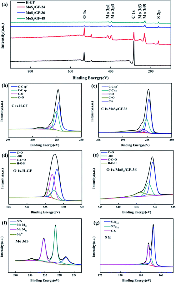
The local elemental compositions of the electrodes are analyzed via XPS (Fig. 5). As shown in Fig. 5(a), the GF consists of two elements, namely, C and O. For the MoS2/GF-X electrode, new peaks corresponding to the Mo and S elements are observed. For further insight into the binding mode of GF to MoS2 and the composition of oxygen-containing functional groups on GF, the spectra of C 1s and O 1s are analyzed, with the results shown in Fig. 5(b)–(e) and Table 1. According to the C 1s spectra of MoS2/GF-36 electrode, the C functional groups mainly consist of C–C sp2, C–C sp, C–O, C![[double bond, length as m-dash]](https://www.rsc.org/images/entities/char_e001.gif) O and a surplus peak that can be ascribed to C–S bond.41–44 This result fully demonstrates that MoS2 was successfully grafted onto GF. Furthermore, besides the C–S bond in MoS2/GF-36, GF and MoS2 may be firmly stacked by interlayer van der Waals attraction similar to graphene because of the surface energy minimization.43,45,46 Based on the O 1s spectrum, it can be convoluted into four peaks of C
O and a surplus peak that can be ascribed to C–S bond.41–44 This result fully demonstrates that MoS2 was successfully grafted onto GF. Furthermore, besides the C–S bond in MoS2/GF-36, GF and MoS2 may be firmly stacked by interlayer van der Waals attraction similar to graphene because of the surface energy minimization.43,45,46 Based on the O 1s spectrum, it can be convoluted into four peaks of C![[double bond, length as m-dash]](https://www.rsc.org/images/entities/char_e001.gif) O, –OH, C–C
O, –OH, C–C![[double bond, length as m-dash]](https://www.rsc.org/images/entities/char_e001.gif) O and H–O–H,13,16,47 and the fitting results show that the GF with grafted MoS2 flower-like microspheres significantly enhances the –OH content, which is attributed to the C–C
O and H–O–H,13,16,47 and the fitting results show that the GF with grafted MoS2 flower-like microspheres significantly enhances the –OH content, which is attributed to the C–C![[double bond, length as m-dash]](https://www.rsc.org/images/entities/char_e001.gif) O bond cleavage and the synthesis of the –OH bond. It has been demonstrated that an increase in the oxygen-containing functional groups on the surface of the electrode can provide more active sites and enhance the VO2+/VO2+ redox reaction.48–50 Therefore, the prominent enhancement of –OH, which is a primarily important precursors for electron transfer in VO2+/VO2+ redox couples, can be beneficial for improving the performance of the vanadium battery.
O bond cleavage and the synthesis of the –OH bond. It has been demonstrated that an increase in the oxygen-containing functional groups on the surface of the electrode can provide more active sites and enhance the VO2+/VO2+ redox reaction.48–50 Therefore, the prominent enhancement of –OH, which is a primarily important precursors for electron transfer in VO2+/VO2+ redox couples, can be beneficial for improving the performance of the vanadium battery.
| Electrode | C![[double bond, length as m-dash]](https://www.rsc.org/images/entities/char_e001.gif) O (%) O (%) |
–OH (%) | C–C![[double bond, length as m-dash]](https://www.rsc.org/images/entities/char_e001.gif) O (%) O (%) |
H–O–H (%) |
|---|---|---|---|---|
| H-GF | 46.86 | 14.35 | 31.22 | 7.57 |
| MoS2/GF-36 | 55.56 | 23.37 | 0 | 21.07 |
In addition, the Mo 3d spectrum is also analyzed, where the four different peaks respectively correspond to the S 2s of MoS2, the Mo 3d5/2 and Mo 3d3/2 of Mo3+ in MoS2 and the Mo 3d of MoO3, which may be attributed to the oxidation of the sample in air (Fig. 5(f)).40 Thereafter, the sulfur species are determined by the XPS S 2p spectrum, which has two peaks: the S 2p3/2 and S 2p1/2 lines of MoS2, indicating the presence of bridged S22− or apical S2−, respectively.51–54 It is noteworthy that the extra peaks in S 2p plot of MoS2/GF-36 can be assigned to C–S bond,41,44,55 which is in accord with the XPS results of C 1s. Combined with the above SEM, XRD, and TEM results, it is not difficult to determine that the 3D flower-like MoS2 microsphere modified GF electrode could absorb more vanadium ions and enhance the ion transfer and VO2+/VO2+ redox reaction.
3.2 Electrochemical characterization
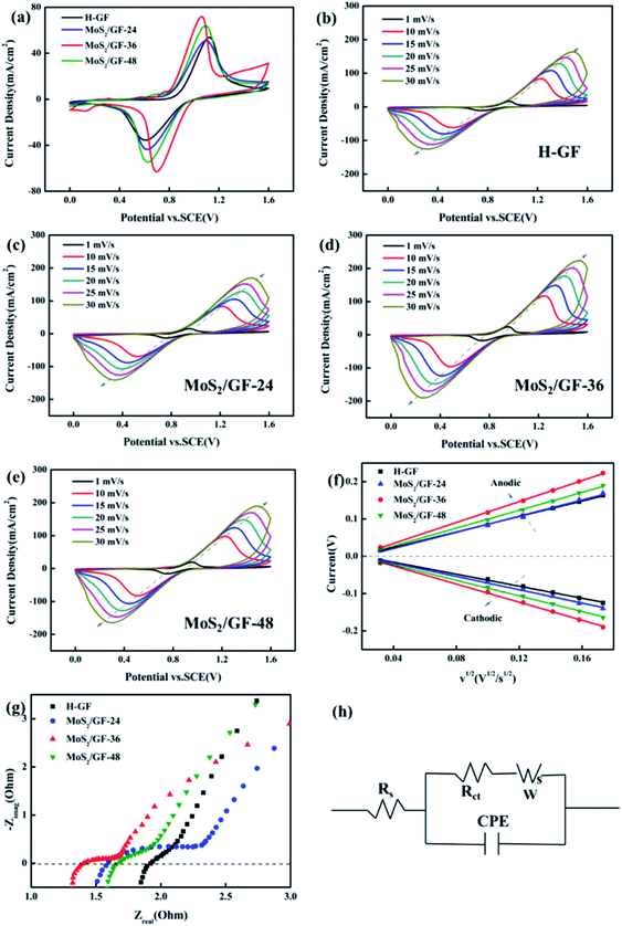
To further experimentally verify the enhancement of the VO2+/VO2+ redox reaction by the MoS2/GF-X electrodes, the CV of the electrodes is investigated and shown in Fig. 6(a). Several parameters are employed to evaluate its catalytic activity including the peak potential separation (ΔEp = Epa − Epc), redox onset potential, peak current density (Ipa and Ipc) and peak current density ratio (Ipa/Ipc), with the detailed parameters summarized in Table 2. Significant differences between all the electrodes are observed. The MoS2/GF-X electrodes almost present high anodic/cathodic peak current, and small ΔEp and Ipa/Ipc, indicating the improvement of the electrocatalytic activity and reaction reversibility, especially for the MoS2/GF-36 electrode. In addition, the MoS2/GF-36 electrode delivers the smallest onset potentials of the oxidation and the highest onset potentials of the reduction process, suggesting an enhancement of the electrocatalytic kinetic of the oxidation and reduction process. The optimal electrochemical activity and reversibility of the MoS2/GF-36 electrode verify that the 3D flower-like MoS2 microsphere has a positive effect for the VRFB battery.| Electrode | Ipa (mA cm−2) | Ipc (mA cm−2) | Epa (V) | Epc (V) | Ipa/Ipc | ΔEp (V) |
|---|---|---|---|---|---|---|
| H-GF | 53.79 | −35.53 | 1.13 | 0.61 | 1.51 | 0.52 |
| MoS2/GF-24 | 50.81 | −43.61 | 1.10 | 0.62 | 1.17 | 0.48 |
| MoS2/GF-36 | 71.85 | −63.04 | 1.06 | 0.70 | 1.14 | 0.36 |
| MoS2/GF-48 | 64.03 | −54.57 | 1.09 | 0.63 | 1.17 | 0.46 |
To further investigate the effects of the MoS2 catalysts on the kinetics of the VO2+/VO2+ redox reaction, a series of CV plots for various electrodes at different scan rates from 1 to 30 mV s−1 are recorded and shown in Fig. 6(b)–(e). It can be seen from Fig. 6(f) that the anode and cathode peak currents of all the electrodes are linear with the square root of the scanning rate (ν1/2), thus the ion diffusion coefficient can be estimated according to eqn (4).54,56,57
 | (4) |
 | (5) |
Based on the above equation, the diffusion coefficient of the electrodes can be calculated and summarized in Table 3. As observed, the D0 of each electrode for VO2+ → VO2+ is MoS2/GF-36 > MoS2/GF-48 > MoS2/GF-36 > H-GF, and a similar trend is found for VO2+ → VO2+. This illustrates that the MoS2/GF-36 electrode with a 3D flower-like structure enhances the ion transfer in the electrode and presents the best electrochemical activity for the VO2+/VO2+ redox reaction.
| Electrode | D0 (10−8 cm2 s−1) for VO2+→ VO2+ | D0 (10−8 cm2 s−1) for VO2+→ VO2+ |
|---|---|---|
| H-GF | 2.58 | 1.56 |
| MoS2/GF-24 | 2.80 | 1.91 |
| MoS2/GF-36 | 4.74 | 3.54 |
| MoS2/GF-48 | 3.44 | 2.63 |
To understand the electronic charge transfer mechanism in the prepared electrodes, EIS measurements were performed at the open circuit voltage (OCP). All the obtained Nyquist plots (Fig. 6(g)) are composed of a semicircle portion in the high-frequency region and a linear portion in the low-frequency region, indicating that the redox process on the electrode surface is a mix that is controlled by the charge transfer and diffusion steps. Fig. 6(h) shows the equivalent circuit diagram of the Randles circuit and the fitting date are listed in Table 4. Rs represents the total resistance of the electrolyte and electrode, Rct represents the charge transfer resistance, CPE is the constant-phase element, which represents the double-layer capacitance of the electrode/solution interface and W is the Warburg impedance. Among them, the MoS2/GF-36 electrode has the smallest Rs and Rct, suggesting it has good conductivity and fast electron transfer.
| Electrode | H-GF | MoS2/GF-24 | MoS2/GF-36 | MoS2/GF-48 |
| Rs (Ω) | 2.04 | 2.13 | 1.58 | 1.81 |
| Rct (Ω) | 11.27 | 20.96 | 0.01 | 0.31 |
3.3 VRFB single cell performance
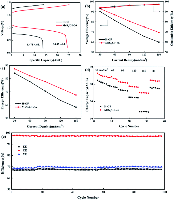
Based on the above results, the MoS2/GF-36 electrode was assembled in the battery as the positive electrode to test the charge/discharge performance, the H-GF electrode was also measured for comparison with the results shown in Fig. 7 and Table 5. Comparing the H-GF electrode, the MoS2/GF-36 electrode presents a lower charging voltage plateau (reducing by 100.50 mV) and a higher discharge voltage plateau (increasing by 195.10 mV), and a significant increase in the discharge capacity (an increase of 78.19%) is observed, suggesting the MoS2/GF-36 electrode exhibits a high electrochemical catalysis for the vanadium ions (Fig. 7(a)). For the battery efficiency, a gain in voltage efficiency (VE) and energy efficiency (EE) is found by using the MoS2/GF-36 electrode instead of the H-GF electrode (Fig. 7(b) and (c)). In particular, at a high current density of 150 mA cm−2, the MoS2/GF-36 electrode show a significant increase in VE and EE of 9.59% and 9.22%, respectively. However, the CE of the MoS2/GF-36 and H-GF electrodes are almost equal and slightly increase as the current density increases. In Fig. 7(d), since the polarization overpotential of H-GF is significantly increased, the difference in the charge capacity of the two electrodes remarkably increases as the current density increases. Therefore, at a high current density of 150 mA cm−2, the charge capacity of the MoS2/GF-36 electrode is 24.97 A h L−1, which is 1.77 times the charge capacity of H-GF (14.06 A h L−1). In Fig. 7(e), the MoS2/GF-36 electrode is subjected to a long cycle test at a current density of 150 mA cm−2. After 100 cycles, the VE, CE and EE of the MoS2/GF-36 electrode remain almost unchanged, the MoS2 were well retained on the electrode (Fig. S1†), signifying the excellent long-term stability of the electrode.| Current density (mA cm−2) | MoS2/GF-36 | H-GF | ||||
|---|---|---|---|---|---|---|
| EE (%) | CE (%) | VE (%) | EE (%) | CE (%) | VE (%) | |
| 30 | 87.47 | 94.03 | 92.97 | 84.18 | 93.3 | 90.22 |
| 60 | 82.21 | 94.55 | 86.96 | 77.73 | 95.44 | 81.44 |
| 90 | 77.76 | 96.44 | 80.64 | 70.54 | 96.22 | 73.31 |
| 120 | 72.63 | 96.83 | 75.00 | 63.48 | 96.76 | 65.60 |
| 150 | 67.693 | 97.2 | 69.58 | 58.41 | 97.38 | 59.99 |
The probable catalytic mechanism on the MoS2/GF-36 electrode towards the VO2+/VO2+ redox reaction can be shown in Fig. 8. The compactly contacts through C–S bond between GF and MoS2, so the special structure of MoS2 provides effective electron transport paths for vanadium ions, allowing the electrolyte to enter the nanosheet gap. Therefore, VO2+/VO2+ redox reaction occurs inside and outside the nanosheet. At the same time, VO2+/VO2+ also promotes the redox reaction by the oxygen-containing functional group –OH binding on GF. In addition, the 3D flower structure of MoS2 on the surface of GF enhances the contact area between the electrode and the electrolyte, greatly shortens the diffusion distance and accelerates the charge mass transfer process. Therefore, the successful combination of GF and MoS2 produces extraordinary electrochemical and battery performance.
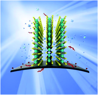 | ||
| Fig. 8 Schematic illustration of the redox reaction mechanism proposed for the VO2+/VO2+ redox couple on the surface of the MoS2/GF-36 electrode in a VRFB. | ||
4. Conclusion
In summary, a safe and simple hydrothermal method was applied to grow 3D flower-like MoS2 nanosheets on a GF electrode for the first time. The morphology and loading of the MoS2 nanosheets onto the surface of the GF electrode played an important role in determining the electrochemical performance of the electrocatalyst. The electrochemical properties, reversibility, and electrical conductivity of all the MoS2/GF electrodes were significantly improved compared to the H-GF electrode. The kinetic studies showed that MoS2/GF electrodes promote the diffusion process, which promotes the VO2+/VO2+ redox reaction. At a high current density of 150 mA cm−2, the EE and the discharge capacities of the MoS2/GF-36 electrode were increased by 9.22% and 10.57 A h L−1, respectively. The charge–discharge stability test showed that the efficiency was not attenuated after 100 cycles, indicating the optimal stability of the MoS2-modified GF electrode in a strongly acidic electrolyte. The above results are attributed to the faster electron transfer due to the open structure of MoS2, the ultrawide layer spacing, and the rich oxygen-containing functional groups, which accelerate the redox reaction of the surface of the MoS2/GF-36 electrode. We believe this material can be a promising candidate for the development of a high performance VRFB.Conflicts of interest
There are no conflicts to declare.Acknowledgements
This research work was supported by the National Natural Science Foundation of China (21676139, 21838005), the Six Talent Peaks Project in Jiangsu Province (JNHB-036), the National Key Research and Development Program of China (2017YFB0306901), and the Key Scientific Research and Development Projects of Jiangsu Province (BE201800903).References
- B. Dunn, H. Kamath and J. M. Tarascon, Electrical energy storage for the grid: a battery of choices, Science, 2011, 334, 928–935 CrossRef CAS PubMed.
- A. R. Dehghani-Sanij, E. Tharumalingam, M. B. Dusseault and R. Fraser, Study of energy storage systems and environmental challenges of batteries, Renewable Sustainable Energy Rev., 2019, 104, 192–208 CrossRef.
- P. Alotto, M. Guarnieri and F. Moro, Redox flow batteries for the storage of renewable energy: A review, Renewable Sustainable Energy Rev., 2014, 29, 325–335 CrossRef CAS.
- M. Skyllas-Kazacos, M. H. Chakrabarti, S. A. Hajimolana, F. S. Mjalli and M. Saleem, Progress in flow battery research and development, J. Electrochem. Soc., 2011, 158, R55–R79 CrossRef CAS.
- J. Noack, N. Roznyatovskaya, T. Herr and P. Fischer, The chemistry of redox-flow batteries, Angew. Chem., Int. Ed., 2015, 54, 9775–9808 CrossRef PubMed.
- X. Luo, J. Wang, M. Dooner and J. Clarke, Overview of current development in electrical energy storage technologies and the application potential in power system operation, Appl. Energy, 2015, 137, 511–536 CrossRef.
- B. Fang, Y. Wei, T. Arai, S. Iwasa and M. Kumagai, Development of a novel redox flow battery for electricity storage system, J. Appl. Electrochem., 2003, 33, 197–203 CrossRef CAS.
- B. Fang, S. Iwasa, Y. Wei, T. Arai and M. Kumagai, A study of the Ce(III)/Ce(IV) redox couple for redox flow battery application, Electrochim. Acta, 2002, 47, 3971–3976 CrossRef CAS.
- Y. Wei, B. Fang, T. Arai and M. Kumagai, Electrolytic oxidation of Ce(III) in nitric acid and sulfuric acid media using a flow type cell, J. Appl. Electrochem., 2005, 35, 561–566 CrossRef CAS.
- M. Skyllas-Kazacos, L. Cao, M. Kazacos, N. Kausar and A. Mousa, Vanadium electrolyte studies for the vanadium redox battery A Review, ChemSusChem, 2016, 9, 1521–1543 CrossRef CAS PubMed.
- Y. Shao, X. Wang, M. Engelhard, C. Wang, S. Dai, J. Liu, Z. Yang and Y. Lin, Nitrogen-doped mesoporous carbon for energy storage in vanadium redox flow batteries, J. Power Sources, 2010, 195, 4375–4379 CrossRef CAS.
- J. Jin, X. Fu, Q. Liu, Y. Liu, Z. Wei, K. Niu and J. Zhang, Identifying the active site in nitrogen-doped graphene for the VO2+/VO2+ redox reaction, ACS Nano, 2013, 7, 4764–4773 CrossRef CAS PubMed.
- P. Hien Thi Thu, C. Jo, J. Lee and Y. Kwon, MoO2 nanocrystals interconnected on mesocellular carbon foam as a powerful catalyst for vanadium redox flow battery, RSC Adv., 2016, 6, 17574–17582 RSC.
- S. Fu, C. Zhu, J. Song, M. H. Engelhard, D. Du and Y. Lin, Three-dimensional nitrogen-doped reduced graphene oxide/carbon nanotube composite catalysts for vanadium flow batteries, Electroanalysis, 2017, 29, 1469–1473 CrossRef CAS.
- M. Vijayakumar, W. Wang, Z. Nie, V. Sprenkle and J. Hu, Elucidating the higher stability of vanadium(V) cations in mixed acid based redox flow battery electrolytes, J. Power Sources, 2013, 241, 173–177 CrossRef CAS.
- A. W. Bayeh, D. M. Kabtamu, Y. C. Chang, G. C. Chen, H. Y. Chen, G. Y. Lin, T. R. Liu, T. H. Wondimu, K. C. Wang and C. H. Wang, Ta2O5-nanoparticle-modified graphite felt as a high-performance electrode for a vanadium redox flow battery, ACS Sustainable Chem. Eng., 2018, 6, 3019–3028 CrossRef CAS.
- P. Leung, X. Li, C. P. de Leon, L. Berlouis, C. T. J. Low and F. C. Walsh, Progress in redox flow batteries, remaining challenges and their applications in energy storage, RSC Adv., 2012, 2, 10125–10156 RSC.
- M. H. Chakrabarti, N. P. Brandon, S. A. Hajimolana, E. Tariq, V. Yufit, M. A. Hashim, M. A. Hussain, C. T. J. Low and P. V. Aravind, Application of carbon materials in redox flow batteries, J. Power Sources, 2014, 253, 150–166 CrossRef CAS.
- D. S. Yang, J. Y. Lee, S. W. Jo, S. J. Yoon, T. H. Kim and Y. T. Hong, Electrocatalytic activity of nitrogen-doped CNT graphite felt hybrid for all-vanadium redox flow batteries, Int. J. Hydrogen Energy, 2018, 43, 1516–1522 CrossRef CAS.
- Y. Xiang and W. A. Daoud, Investigation of an advanced catalytic effect of cobalt oxide modification on graphite felt as the positive electrode of the vanadium redox flow battery, J. Power Sources, 2019, 416, 175–183 CrossRef CAS.
- Y. Xiang and W. A. Daoud, Binary NiCoO2-modified graphite felt as an advanced positive electrode for vanadium redox flow batteries, J. Mater. Chem. A, 2019, 7, 5589–5600 RSC.
- Y. H. Wang, I. M. Hung and C. Y. Wu, The characteristics and electrochemical performance of graphite felts with thermal and fenton's reagent treatment for vanadium redox flow battery, Ceram. Int., 2018, 44, S30–S33 CrossRef CAS.
- D. M. Kabtamu, A. W. Bayeh, T. C. Chiang, Y. C. Chang, G. Y. Lin, T. H. Wondimu, S. K. Su and C. H. Wang, TiNb2O7 nanoparticle-decorated graphite felt as a high-performance electrode for vanadium redox flow batteries, Appl. Surf. Sci., 2018, 462, 73–80 CrossRef CAS.
- Y. Gao, H. Wang, Q. Ma, A. Wu, W. Zhang, C. Zhang, Z. Chen, X. X. Zeng, X. Wu and Y. Wu, Carbon sheet-decorated graphite felt electrode with high catalytic activity for vanadium redox flow batteries, Carbon, 2019, 148, 9–15 CrossRef CAS.
- M. Etienne, J. F. Vivo-Vilches, I. Vakulko, C. Genois, L. Liu, M. Perdicakis, R. Hempelmann and A. Walcarius, Layer-by-Layer modification of graphite felt with MWCNT for vanadium redox flow battery, Electrochim. Acta, 2019, 313, 131–140 CrossRef CAS.
- L. Wu, Y. Shen, L. Yu, J. Xi and X. Qiu, Boosting vanadium flow battery performance by Nitrogen-doped carbon nanospheres electrocatalyst, Nano Energy, 2016, 28, 19–28 CrossRef CAS.
- L. Yu, F. Un, W. Xiao, L. Xu and J. Xi, Achieving efficient and inexpensive vanadium flow battery by combining CexZr1−xO2 electrocatalyst and hydrocarbon membrane, Chem. Eng. J., 2019, 356, 622–631 CrossRef CAS.
- Y. Liu, Y. Shen, L. Yu, L. Liu, F. Liang, X. Qiu and J. Xi, Holey-engineered electrodes for advanced vanadium flow batteries, Nano Energy, 2018, 43, 55–62 CrossRef CAS.
- C. Zhao, C. Yu, M. Zhang, Q. Sun, S. Li, M. N. Banis, X. Han, Q. Dong, J. Yang, G. Wang, X. Sun and J. Qiu, Enhanced sodium storage capability enabled by super wide-interlayer-spacing MoS2 integrated on carbon fibers, Nano Energy, 2017, 41, 66–74 CrossRef CAS.
- J. Liu, T. Ma, M. Zhou, S. Liu, J. Xiao, Z. Tao and J. Chen, MoS2-modified graphite felt as a high performance electrode material for zinc-polyiodide redox flow batteries, Inorg. Chem. Front., 2019, 6, 731–735 RSC.
- J. Wang, C. Luo, T. Gao, A. Langrock, A. C. Mignerey and C. Wang, An advanced MoS2/Carbon anode for high-performance Sodium-Ion batteries, Small, 2015, 11, 473–481 CrossRef CAS PubMed.
- X. Zhang, X. Huang, M. Xue, X. Ye, W. Lei, H. Tang and C. Li, Hydrothermal synthesis and characterization of 3D flower-like MoS2 microspheres, Mater. Lett., 2015, 148, 67–70 CrossRef CAS.
- G. Tang, Y. Wang, W. Chen, H. Tang and C. Li, Hydrothermal synthesis and characterization of novel flowerlike MoS2 hollow microspheres, Mater. Lett., 2013, 100, 15–18 CrossRef CAS.
- C. Burda, X. B. Chen, R. Narayanan and M. A. El-Sayed, Chemistry and properties of nanocrystals of different shapes, Chem. Rev., 2005, 105, 1025–1102 CrossRef CAS PubMed.
- S. Min and G. Lu, Sites for high efficient photocatalytic hydrogen evolution on a limited-layered MoS2 cocatalyst confined on graphene sheets-The role of graphene, J. Phys. Chem. C, 2012, 116, 25415–25424 CrossRef CAS.
- H. Zhou, J. Xi, Z. Li, Z. Zhang, L. Yu, L. Liu, X. Qiu and L. Chen, CeO2 decorated graphite felt as a high-performance electrode for vanadium redox flow batteries, RSC Adv., 2014, 4, 61912–61918 RSC.
- A. Wu, C. Tian, Y. Jiao, Q. Yan, G. Yang and H. Fu, Sequential two-step hydrothermal growth of MoS2/CdS core-shell heterojunctions for efficient visible light-driven photocatalytic H2− evolution, Appl. Catal., B, 2017, 203, 955–963 CrossRef CAS.
- S. He and W. Chen, Application of biomass-derived flexible carbon cloth coated with MnO2 nanosheets in supercapacitors, J. Power Sources, 2015, 294, 150–158 CrossRef CAS.
- D. Chen, J. Shen, X. Jiang, Y. Mu, D. Ma, W. Han, X. Sun, J. Li and L. Wang, Fabrication of polypyrrole/beta-MnO2 modified graphite felt anode for enhancing recalcitrant phenol degradation in a bioelectrochemical system, Electrochim. Acta, 2017, 244, 119–128 CrossRef CAS.
- X. Zheng, J. Xu, K. Yan, H. Wang, Z. Wang and S. Yang, Space-confined growth of MoS2 nanosheets within graphite: The layered hybrid of MoS2 and graphene as an active catalyst for hydrogen evolution reaction, Chem. Mater., 2014, 26, 2344–2353 CrossRef CAS.
- C. Zu and A. Manthiram, Hydroxylated graphene-sulfur nanocomposites for high-rate Lithium-Sulfur batteries, Adv. Energy Mater., 2013, 3, 1008–1012 CrossRef CAS.
- A. D. Vogt, T. Han and T. P. Beebe, Adsorption of 11-mercaptoundecanoic acid on Ni(111) and its interaction with probe molecules, Langmuir, 1997, 13, 3397–3403 CrossRef CAS.
- J. Gao, J. He, N. Wang, X. Li, Z. Yang, K. Wang, Y. Chen, Y. Zhang and C. Huang, Robust C–S bond integrated graphdiyne-MoS2 nanohybrids for enhanced lithium storage capability, Chem. Eng. J., 2019, 373, 660–667 CrossRef CAS.
- D. Chao, C. Zhu, P. Yang, X. Xia, J. Liu, J. Wang, X. Fan, S. V. Savilov, J. Lin, H. J. Fan and Z. X. Shen, Array of nanosheets render ultrafast and high-capacity Na-ion storage by tunable pseudocapacitance, Nat. Commun., 2016, 7, 1–8 Search PubMed.
- X. Xie, Z. Ao, D. Su, J. Zhang and G. Wang, MoS2/Graphene composite anodes with enhanced performance for Sodium-Ion batteries: The role of the two-dimensional heterointerface, Adv. Funct. Mater., 2015, 25, 1393–1403 CrossRef CAS.
- T. S. Sahu and S. Mitra, Exfoliated MoS2 sheets and reduced graphene oxide-an excellent and fast anode for Sodium-ion battery, Sci. Rep., 2015, 5 DOI:10.1038/srep12571.
- D. M. Kabtamu, J. Y. Chen, Y. C. Chang and C. H. Wang, Water-activated graphite felt as a high-performance electrode for vanadium redox flow batteries, J. Power Sources, 2017, 341, 270–279 CrossRef CAS.
- L. Yue, W. Li, F. Sun, L. Zhao and L. Xing, Highly hydroxylated carbon fibres as electrode materials of all-vanadium redox flow battery, Carbon, 2010, 48, 3079–3090 CrossRef CAS.
- B. Sun and M. Skyllas-Kazacos, Chemical modification of graphite electrode materials for vanadium redox flow battery application. 2. acid treatments, Electrochim. Acta, 1992, 37, 2459–2465 CrossRef CAS.
- K. J. Kim, M. S. Park, Y. J. Kim, J. H. Kim, S. X. Dou and M. Skyllas-Kazacos, A technology review of electrodes and reaction mechanisms in vanadium redox flow batteries, J. Mater. Chem. A, 2015, 3, 16913–16933 RSC.
- X. Y. Yu, Y. Feng, Y. Jeon, B. Guan, X. W. Lou and U. Paik, Formation of Ni-Co-MoS2 nanoboxes with enhanced electrocatalytic activity for hydrogen evolution, Adv. Mater., 2016, 28, 9006–9011 CrossRef CAS PubMed.
- H. Yu, Y. Xue, L. Hui, C. Zhang, Y. Li, Z. Zuo, Y. Zhao, Z. Li and Y. Li, Efficient hydrogen production on a 3D flexible heterojunction material, Adv. Mater., 2018, 30, 1–7 Search PubMed.
- Y. Yang, H. Fei, G. Ruan, C. Xiang and J. M. Tour, Edge-oriented MoS2 nanoporous films as flexible electrodes for hydrogen evolution reactions and supercapacitor devices, Adv. Mater., 2014, 26, 8163–8168 CrossRef CAS PubMed.
- Y. Yan, B. Xia, X. Ge, Z. Liu, J. Y. Wang and X. Wang, Ultrathin MoS2 nanoplates with rich active sites as highly efficient catalyst for hydrogen evolution, ACS Appl. Mater. Interfaces, 2013, 5, 12794–12798 CrossRef CAS PubMed.
- B. Zhao, Y. Yang, Z. Wang, S. Huang, Y. Wang, S. Wang, Z. Chen and Y. Jiang, In situ sulfuration synthesis of sandwiched spherical tin sulfide/sulfur-doped graphene composite with ultra-low sulfur content, J. Power Sources, 2018, 378, 81–89 CrossRef CAS.
- C. Tang and D. Zhou, Methanesulfonic acid solution as supporting electrolyte for zinc-vanadium redox battery, Electrochim. Acta, 2012, 65, 179–184 CrossRef CAS.
- J. Hwang, B. m. Kim, J. Moon, A. Mehmood and H. Y. Ha, A highly efficient and stable organic additive for the positive electrolyte in vanadium redox flow batteries: taurine biomolecules containing –NH2 and –SO3H functional groups, J. Mater. Chem. A, 2018, 6, 4695–4705 RSC.
Footnote |
| † Electronic supplementary information (ESI) available. See DOI: 10.1039/d0ra02541k |
| This journal is © The Royal Society of Chemistry 2020 |

