 Open Access Article
Creative Commons Attribution 3.0 Unported Licence
Multi-step hydration/dehydration mechanisms of rhombohedral Y2(SO4)3: a candidate material for low-temperature thermochemical heat storage†
Kunihiko Shizume *,
Naoyuki Hatada*,
Shoko Yasui and
Tetsuya Uda*
Department of Materials Science and Engineering, Kyoto University, Yoshida Honmachi, Sakyo-ku, Kyoto, 606-8501, Japan. E-mail: shizume.kunihiko.26z@st.kyoto-u.ac.jp; hatada.naoyuki.8u@kyoto-u.ac.jp; uda.tetsuya.5e@kyoto-u.ac.jp
First published on 21st April 2020
Abstract
To evaluate rhombohedral Y2(SO4)3 as a new potential material for low-temperature thermochemical energy storage, its thermal behavior, phase changes, and hydration/dehydration reaction mechanisms are investigated. Rhombohedral Y2(SO4)3 exhibits reversible hydration/dehydration below 130 °C with relatively small thermal hysteresis (less than 50 °C). The reactions proceed via two reaction steps in approximately 0.02 atm of water vapor pressure, i.e. “high-temperature reaction” at 80–130 °C and “low-temperature reaction” at 30–100 °C. The high-temperature reaction proceeds by water insertion into the rhombohedral Y2(SO4)3 host structure to form rhombohedral Y2(SO4)3·xH2O (x = ∼1). For the low-temperature reaction, rhombohedral Y2(SO4)3·xH2O accommodates additional water molecules (x > 1) and is eventually hydrated to Y2(SO4)3·8H2O (monoclinic) with changes in the host structure. At a water vapor pressure above 0.08 atm, intermediate Y2(SO4)3·3H2O appears. A phase stability diagram of the hydrates is constructed and the potential usage of Y2(SO4)3 for thermal energy upgrades is assessed. The high-temperature reaction may act similarly to an existing candidate, CaSO4·0.5H2O, in terms of reaction temperature and water vapor pressure. Additionally, the hydration of rhombohedral Y2(SO4)3·xH2O to Y2(SO4)3·3H2O should exhibit a larger heat storage capacity. With respect to the reaction kinetics, the initial dehydration of Y2(SO4)3·8H2O to rhombohedral Y2(SO4)3 introduces a microstructure with pores on the micron order, which might enhance the reaction rate.
1. Introduction
Thermal energy storage based on chemical reactions (TCHS: thermochemical heat storage) is a prospective technology for the reduction of fossil-fuel consumption by storing waste heat.1,2 One of the expected roles of TCHS is storing and utilizing heat below 250 °C, where abundant low-grade waste heat and solar energy might be available. For widespread application, a critical challenge is to identify appropriate reversible dehydration/hydration reaction systems satisfying following criteria: suitable reaction temperature, enabling high heat storage capacity, fast enough reaction rate and heat output rate, long-term stability of thermophysical and mechanical properties including, for example, no liquefaction due to melting or deliquescence, non-toxicity of materials themselves and reaction products, the low cost of materials, etc.3 Solid–gas reactions using water vapor as a reactive gas (dehydration/hydration reactions) are favorable because water is safe and easily stored via condensation. To date, various salt hydrates, whose dehydration/hydration reactions can be operated below 250 °C, have been proposed, for example, MgSO4·nH2O (n = 0–7),4–6 CaCl2·nH2O (n = 0–6),7 LiOH·H2O,8–10 Na2S·5H2O,11,12 and CaSO4·0.5H2O.13,14 However, these salt hydrates suffer from some undesirable behaviors related to hydration kinetics and cycle performance.‡ Despite numerous efforts related to the modification of material properties such as developing composite materials based on these salt hydrates, no materials have been widely used yet.Recently, we reported the dehydration/hydration of β-La2(SO4)3·H2O as a new candidate reaction for TCHS below 250 °C.15–17 The reactions proceed by insertion/deinsertion of the H2O guest molecules into β-La2(SO4)3 host lattices,§ which leads the rapid and reversible dehydration/hydration reaction even at low-temperature below 250 °C. Furthermore, β-La2(SO4)3 is non-toxic and does not show melting and deliquescence. However, the heat storage capacity is insufficient due to the small changes in the hydration water content (β-La2(SO4)3·H2O: 3.2 mass% anhydrous basis). There is still a need to find other materials.
In this study, we focused on Y2(SO4)3 as a new candidate material for the low-temperature TCHS system. Y2(SO4)3 is another trivalent-rare-earth sulfate with a chemical formula analogous to that of β-La2(SO4)3 but it has a crystal structure belonging to the rhombohedral system (space group: No. 148).19 Due to the differences of rare-earth elements and crystal structures, the hydration/dehydration behavior of rhombohedral Y2(SO4)3 should differ from that of β-La2(SO4)3 (monoclinic system, space group: 15). Thus it is worthwhile to investigate if rhombohedral Y2(SO4)3 shows favorable hydration/dehydration behaviors. See ESI-1† for their crystal structures. Though there are a few studies associated with the phase changes, reaction temperature, and enthalpy changes on dehydration of Y2(SO4)3·8H2O,20–22 the backward hydration reaction behaviors have not been reported. In addition, Y2O3, the raw material of Y2(SO4)3, is oversupplied, so the cost is not expensive at this time, 3 USD kg−1 in 2018.23 Therefore, Y2(SO4)3 might be a low-cost candidate for TCHS.
In this work, thermogravimetry (TG) studies of the hydration/dehydration reaction were conducted. High-temperature X-ray diffraction (XRD) investigated the crystal structure changes in the dehydration reaction. Then, we systematically investigated the phases formed in the hydration process under various conditions of temperatures and water vapor pressure pH2O and discussed the available reactions for TCHS system. In addition, we examined the microstructures of Y2(SO4)3 and Y2(SO4)3·8H2O by nitrogen gas adsorption (N2 adsorption), optical microscopy, and transmission electron microscopy (TEM) because the microstructures should influence the dehydration/hydration reaction rates.17
2. Experimental
2.1 Materials
In this paper, a-few-hundreds-μm-large particles of Y2(SO4)3·8H2O (Strem Chemical, 99.9%) were used as the starting material for the syntheses of rhombohedral Y2(SO4)3 by heating Y2(SO4)3·8H2O. The heating processes were either conducted at the time of thermogravimetry, high-temperature XRD and N2 adsorption measurements in the respective apparatus or pre-conducted in a stand-alone furnace.2.2 Thermogravimetry (TG)
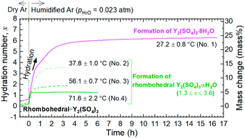
To investigate the dehydration/hydration reaction behavior of rhombohedral Y2(SO4)3, TG was conducted using a Rigaku Thermo plus TG 8120. Y2(SO4)3·8H2O was heated to about 400 °C, which is the temperature where dehydration to the anhydrate should be completed, and subsequently cooled to about 30 °C in the TG apparatus (“first heating–cooling cycle”) under a humidified argon gas (water vapor pressure pH2O = 0.02 atm) flow. At this point, Y2(SO4)3·xH2O was obtained as a rehydrated phase of anhydrate Y2(SO4)3. On the subsequent “second heating–cooling cycle” between 30–160 °C, the dehydration/hydration reaction behaviors of Y2(SO4)3·xH2O were investigated. Isothermal TG measurements at various temperatures in humidified argon (pH2O = 0.023 atm) were conducted on the hydration of rhombohedral Y2(SO4)3. For isothermal TG measurements, Y2(SO4)3·8H2O was used as the starting material and it was dehydrated to rhombohedral Y2(SO4)3 upon heating to 320 °C in dry argon by TG. Subsequently, it was cooled to arbitrary temperatures and the isothermal hydration reaction started by switching flowing gas from dry argon to humidified argon.In all the TG measurements, the sample material was put in a platinum cylindrical crucible with a diameter of 5 mm and a height of 5 mm and the same empty crucible was used as the reference.
2.3 X-ray diffraction (XRD)
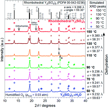
XRD measurements were conducted on a PANalytical X'Pert-Pro MPD using Cu Kα radiation. High-temperature data collection was achieved using an Anton Paar HTK1200N high-temperature oven-chamber under humidified oxygen. For the high-temperature XRD experiments, Y2(SO4)3·8H2O (Strem Chemical, 99.9%) was heated to 300 °C to form rhombohedral Y2(SO4)3 and subsequently, it was cooled to 50 °C to form the hydrated phase Y2(SO4)3·xH2O. The XRD patterns during dehydration of Y2(SO4)3·xH2O were collected on the second heating process from 50 °C to 150 °C. All heating/cooling processes for in situ XRD measurements were conducted under 0.03 atm of pH2O. Rietveld refinement analyses were performed with the help of a commercial software X'Pert HighScorePlus (PANalytical) on the in situ XRD patterns to identify the phase and the lattice parameters of the samples.2.4 Isothermal hydration treatments of Y2(SO4)3 under various temperature and pH2O
The phases formed by the hydration of Y2(SO4)3 under arbitrary temperatures (37–84 °C) and pH2O (0.03–0.4 atm) were investigated by isothermal hydration treatments using two electric furnaces. Rhombohedral Y2(SO4)3 was prepared by dehydration of Y2(SO4)3·8H2O at 200 °C for 1 hour in air. Rhombohedral Y2(SO4)3 (0.1 g) was placed in an approximately 60 mL closed vessel. The vessel and a tank with water were put in separate furnaces and they were connected by the gas line across the furnaces. The vessel was maintained at a constant temperature for 3 hours while the pH2O control was performed by flowing humidified argon gas at a rate of 200 mL min−1 bubbled through water kept at a constant temperature. A ribbon heater was wrapped around the gas line outside the furnaces and kept over 80 °C to prevent condensation of water vapor in humidified argon gas.The phases of the sample after the hydration treatments were identified by XRD. Fourteen batches under different conditions of temperature and pH2O were examined. Based on the results of the isothermal TG and hydration treatments, the phase stability diagram of Y2(SO4)3 with temperature and water vapor pressure axes (T–pH2O map) was constructed.
2.5 Nitrogen gas adsorption measurements (N2 adsorption)
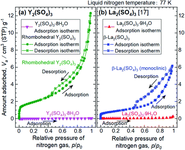
The specific surface areas of the samples were evaluated by N2 adsorption measurements at the liquid nitrogen temperature (77 K) using a BEL JAPAN BELSORP-max. Y2(SO4)3·8H2O (5.758 g) and rhombohedral Y2(SO4)3 (1.321 g), which was prepared by heating Y2(SO4)3·8H2O at 200 °C for 1 hour in air, were placed in a Pyrex glass tube and subjected to a vacuum heating pretreatment. Afterward, N2 adsorption measurements were conducted.2.6 Optical microscope and TEM observations
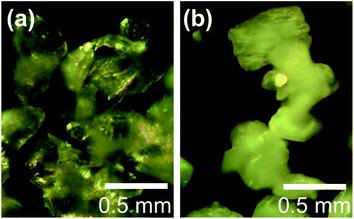
Change in the morphology of the particles during the dehydration process of Y2(SO4)3·8H2O to rhombohedral Y2(SO4)3 was analyzed by optical microscopy using a Nikon L150 L-150II-TI-DIC-A. Y2(SO4)3·8H2O was observed by the optical microscope as it is. Rhombohedral Y2(SO4)3 made by heating Y2(SO4)3·8H2O at 270 °C for 2 hours in air and was observed by the optical microscope.The microstructure inside the rhombohedral Y2(SO4)3 particle was observed by TEM using a JEOL JEM-2100F. The rhombohedral Y2(SO4)3 specimen for the TEM observation was cut out from the particle by a focused ion beam (FIB) using a JEOL JIB-4600F.
3. Results
3.1 Hydration/dehydration reaction behaviors of rhombohedral Y2(SO4)3
Fig. 1 shows a TG curve of rhombohedral Y2(SO4)3 upon cooling/heating in humidified argon. Rhombohedral Y2(SO4)3 can hydrate/dehydrate below 130 °C with relatively small thermal hysteresis (below 50 °C). The change in the hydration number x is greater than 1 and the total mass change in the hydration water content is larger than 10 mass% anhydrous basis. This value is larger than that of La2(SO4)3 (3 mass%) and CaSO4 (6 mass%) and a higher heat storage capacity is expected. Therefore, it may be a suitable material for the temperature range.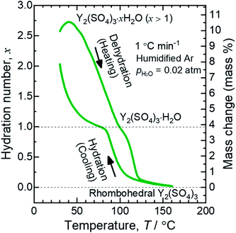 | ||
| Fig. 1 TG curve of rhombohedral Y2(SO4)3 undergoing hydration/dehydration reactions upon cooling/heating. Vertical axis in right side shows the mass changes of the sample. Vertical axis in left side shows apparent hydration number x calculated from the mass change. (Note: This data was presented at IMPRES2019.24) | ||
The TG curve (Fig. 1) suggests that the dehydration/hydration reactions proceed via two reaction steps. The temperature ranges of these two reaction steps are overlapping, preventing them from being clearly distinguished. Between 80–130 °C, apparent hydration number x varies steeply from 0 to approximately 1 (“high-temperature dehydration/hydration reaction”). Below 80 °C, Y2(SO4)3·H2O forms a hydrate with a larger hydration number in the cooling process. The dehydration/hydration reaction proceeds at 30–100 °C (“low-temperature dehydration/hydration reaction”). Both the high-temperature reaction and the low-temperature reaction may be useful for TCHS system. On the other hand, the phase changes in each reaction step are not established. Rosso et al. already reported the relationship between the reaction temperatures and formed hydrate phases of Y2(SO4)3. Y2(SO4)3·4H2O is generated as an intermediate phase in the dehydration process of Y2(SO4)3·8H2O to Y2(SO4)3.21 In contrast, our TG curve (Fig. 1) of rhombohedral Y2(SO4)3 suggest another hydrate phase Y2(SO4)3·H2O. Here, we further investigate in detail the high-temperature and the low-temperature dehydration/hydration reactions.
Hereinafter we refer to the low-temperature hydrate phase below 110 °C as “rhombohedral Y2(SO4)3·xH2O (x ≥ 1)” and the reaction formula of the high-temperature reaction is written as follows:
| Rhombohedral Y2(SO4)3 (s) + H2O (g) ⇄ Rhombohedral Y2(SO4)3·H2O (s) |
At the lower temperatures (between 50–90 °C), the XRD patterns do not exhibit marked changes, but the hydration number x changes with temperature (see Fig. 1), suggesting that rhombohedral Y2(SO4)3·xH2O (x ≥ 1) has a nonstoichiometric hydration number.
| Expt. # | Temp. (°C) | pH2O (atm) | Time (h) | xb | Detected hydrated phasesc | ||||
|---|---|---|---|---|---|---|---|---|---|
| Y2(SO4)3·8H2O | Y2(SO4)3·3H2O | Rhombo-hedrald | Unknown A | Unknown B | |||||
| a “Time” for TG measurements represents the time required for a 90% mass increase relative to the final achieved mass at the end of the measurement.b x: hydration number.c Detected hydrated phases: hydrated phases detected by XRD measurements in the samples after the isothermal TG measurements and the isothermal hydration treatments (No. 1–14). “Strong” and “weak” represent the relative intensity of the XRD peaks derived from each phase. The phase with “strong” corresponds to the main phase formed in the hydration treatments (TG 1–4, IH 1–14) whereas the phase with “weak” corresponds to the secondary phases.d Rhombohedral: Rhombohedral Y2(SO4)3·xH2O | |||||||||
| TG 1 | 27.2 | 0.023 | 3a | 6.3 | Strong | — | Weak | — | — |
| TG 2 | 37.8 | 0.023 | 1a | 3.6 | Weak | — | Strong | — | — |
| TG 3 | 56.1 | 0.023 | 1a | 1.9 | Not measured by XRD | ||||
| TG 4 | 71.6 | 0.023 | 0.2a | 1.3 | Not measured by XRD | ||||
| IH 1 | 38 | 0.043 | 3 | — | Weak | — | Strong | — | — |
| IH 2 | 37 | 0.030 | 3 | — | — | — | Strong | — | — |
| IH 3 | 55 | 0.13 | 3 | — | Strong | Weak | — | — | — |
| IH 4 | 56 | 0.10 | 4 | — | Strong | Weak | — | — | — |
| IH 5 | 55 | 0.088 | 3 | — | — | — | Strong | — | — |
| IH 6 | 55 | 0.079 | 3 | — | — | — | Strong | — | — |
| IH 7 | 69 | 0.24 | 3 | — | Weak | Weak | — | Strong | — |
| IH 8 | 69 | 0.14 | 3 | — | — | — | Strong | — | Weak |
| IH 9 | 79 | 0.40 | 4 | — | Weak | Weak | — | Strong | — |
| IH 10 | 79 | 0.36 | 3 | — | — | Strong | — | Weak | — |
| IH 11 | 79 | 0.32 | 3 | — | — | Strong | — | — | — |
| IH 12 | 78 | 0.18 | 3 | — | — | Weak | Strong | — | Weak |
| IH 13 | 78 | 0.14 | 3 | — | — | — | Strong | — | Weak |
| IH 14 | 84 | 0.44 | 3 | — | — | Strong | — | Weak | — |
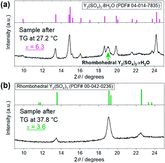 | ||
| Fig. 4 XRD patterns of the Y2(SO4)3·nH2O samples after the TG measurements at (a) 27.2 °C and (b) 37.8 °C shown in Fig. 3. (a) Top figure represents the reference pattern of Y2(SO4)3·8H2O (ICDD (PDF#04-014-7835)). In the bottom figure, there is an XRD peak attributed to the residual rhombohedral Y2(SO4)3·xH2O around 19°. (b) Top figure represents the reference pattern of rhombohedral Y2(SO4)3 (ICDD (PDF#00-042-0236)). | ||
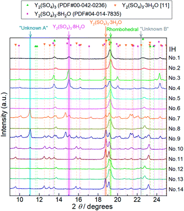 | ||
| Fig. 5 XRD patterns of Y2(SO4)3 hydrate samples after 14 batches of isothermal hydration treatments (IH No. 1–14). Characteristic diffraction angles where distinctive peaks of Y2(SO4)3·8H2O, Y2(SO4)3·3H2O,25 rhombohedral Y2(SO4)3·xH2O (Rhombohedral), Unknown A, and Unknown B exist are highlighted by pink, orange, green, blue, and gray, respectively. Peaks at 11.1° highlighted by a blue belt (No. 7, 9, 10, and 14) do not match any of the reported reference pattern peaks. These peaks are attributed to an unknown hydrated phase Unknown A. Similarly, we assumed that the peak at 22.4° highlighted by gray (No. 8, 12, and 13) is attributed to Unknown B. Doublet peaks around 19° are also attributed to Unknown B. | ||
Depending on the hydration conditions, one or more of three known phases Y2(SO4)3·8H2O (monoclinic), Y2(SO4)3·3H2O (orthorhombic),25,¶ and rhombohedral Y2(SO4)3·xH2O as well as two unknown phases (“Unknown A” and “Unknown B”) are present. Based on the isothermal TG results in Fig. 3, rhombohedral Y2(SO4)3·H2O, which is formed by the high-temperature hydration reaction, further is hydrated to rhombohedral Y2(SO4)3·xH2O (x > 1) and becomes Y2(SO4)3·8H2O (monoclinic) at lower temperatures. Isothermal hydration treatments under relatively high pH2O (>0.08 atm) reveal that another intermediate hydrate Y2(SO4)3·3H2O appears at intermediate temperature.
The isothermal TG measurements indicate that rhombohedral Y2(SO4)3·xH2O has a nonstoichiometric hydration number x (>1). Fig. 3 shows the isothermal TG curves (TG No. 1–4) in the hydration reaction of rhombohedral Y2(SO4)3 at a constant temperature of 27.2 (No. 1), 37.8 (No. 2), 56.1 (No. 3), and 71.6 °C (No. 4) under 0.023 atm of pH2O. The apparent increase in the hydration number x becomes larger as the holding temperature is lowered: x = 1.3 (at 71.6 °C), 1.9 (at 56.1 °C), 3.6 (at 37.8 °C), and 6.3 (at 27.2 °C). Fig. 4(a) and (b) show the XRD patterns of the samples after the isothermal TG measurements at 27.2 °C and 37.8 °C. The pattern of the 6.3 hydrate-equivalent sample confirms the partial formation of Y2(SO4)3·8H2O (monoclinic), while the pattern of the 3.6 hydrate-equivalent sample indicates a single-phasic pattern quite similar to that of rhombohedral Y2(SO4)3·xH2O shown in Fig. 2. Therefore, rhombohedral Y2(SO4)3·xH2O may have a nonstoichiometric hydration number x and accommodate water molecules form x = 1 to at least x = 3.6. Such non-stoichiometry of hydrates has also been reported for MgSO4 – H2O system.4
In the 6.3 hydrate-equivalent sample, the rhombohedral Y2(SO4)3·xH2O phase still remains even after the isothermal TG curve (No. 1) reaches a plateau. This suggests that the hydration reaction of rhombohedral Y2(SO4)3·xH2O to Y2(SO4)3·8H2O was significantly slowed down in the middle of the reaction but the cause is unclear at this time. Based on Gibbs' phase rule, the equilibrium solid phase in the hydration reaction should be a single-phase. Thus Y2(SO4)3·8H2O is regarded as the equilibrium phase in the conditions (27.2 °C, pH2O = 0.023 atm).||
According to the isothermal TG curves, the hydration reactions are almost complete in 3 hours. Therefore, it is reasonable that the equilibrium phases are contained in the detected phases in each batch (No. 1–14) and we can assume that the phase with the largest hydration number is the equilibrium hydrate for each condition. Based on this assumption, we constructed the phase stability diagram of Y2(SO4)3 hydrates with temperature and water vapor pressure (T–pH2O map) shown in Fig. 6. Only Y2(SO4)3·8H2O (monoclinic), Y2(SO4)3·3H2O (orthorhombic), and rhombohedral Y2(SO4)3·xH2O are considered.
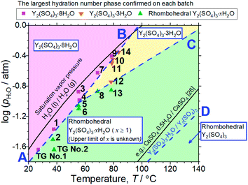 | ||
| Fig. 6 T–pH2O map derived from 14 batches of hydration treatments that expose rhombohedral Y2(SO4)3 under various temperatures and pH2O for 3 hours. Here, only batches No. 4 and 9 are held for 4 hours. Additionally, the results of the isothermal TG measurements (Fig. 3) and the XRD (Fig. 4) are also represented by “TG No. 1” and “TG No. 2”. Pink squares represent batches where Y2(SO4)3·8H2O is formed. Orange inverted triangles represent batches where Y2(SO4)3·3H2O is formed but Y2(SO4)3·8H2O is not. Green triangles represent batches where neither Y2(SO4)3·3H2O and Y2(SO4)3·8H2O are formed. Two-phase equilibria are represented by broken lines. Broken lines A and B show the minimum pH2O and maximum temperature required to form Y2(SO4)3·8H2O. Broken line C also shows those required to form Y2(SO4)3·3H2O. Broken line D represents the equilibrium between rhombohedral Y2(SO4)3 and rhombohedral Y2(SO4)3·H2O. It is drawn using the estimated enthalpy and entropy changes of the dehydration/hydration reaction, determined by TG measurements under four different pH2O. See ESI-2† for the TG curves. Temperature dependences of the saturation vapor pressure of liquid water and the equilibrium between CaSO4 and CaSO4·0.5H2O are also shown.26 | ||
Both Unknown A and Unknown B are not considered in constructing the T–pH2O map for the following reasons. Unknown A and Unknown B are some hydrate phases of Y2(SO4)3. Based on the detected conditions for them, the estimated hydration number of Unknown A is between 3 to 8 and that of Unknown B is between 1 to 3. Unknown A and Unknown B might have stable T–pH2O regions near the broken lines B and C respectively but the regions should not be wide because they are always accompanied by rhombohedral Y2(SO4)3·xH2O, Y2(SO4)3·3H2O, or Y2(SO4)3·8H2O (see Table 1). As Unknown A and Unknown B are intermediate hydrate phases between the considered phases, even though they are omitted in Fig. 6, it should be sufficient to know the outline of the relationship between the hydration conditions and hydration number changes.
3.2 Microstructures of rhombohedral Y2(SO4)3
The microstructures of rhombohedral Y2(SO4)3 obtained by dehydration of Y2(SO4)3·8H2O were investigated. Fig. 7(a) shows the N2 adsorption isotherms of Y2(SO4)3·8H2O and rhombohedral Y2(SO4)3. The specific surface area of rhombohedral Y2(SO4)3 by the BET method (7 m2 g−1) is more than a hundredfold larger than that of the Y2(SO4)3·8H2O (0.05 m2 g−1). ESI-3† shows the BET plots. Fig. 8 shows photographs of (a) Y2(SO4)3·8H2O and (b) rhombohedral Y2(SO4)3·xH2O particles observed by optical microscopy. Note that the hydration number x of the rhombohedral phase was not known unclear accurately because rhombohedral Y2(SO4)3 hydrates to some extent in air. Y2(SO4)3·8H2O particles show facet planes and high transparency, and they are likely a-few-hundreds-μm-large single crystals. On the other hand, rhombohedral Y2(SO4)3·xH2O particles are less transparent representing the polycrystalline nature. Correspondingly, a dark-field TEM image of rhombohedral Y2(SO4)3 in Fig. 9 reveals crevices and voids at a-few-micrometer intervals.** A similar microstructure formation is observed in the case of dehydration of La2(SO4)3·9H2O to β-La2(SO4)3 (Fig. 7(b)), which is known to improve the kinetics of hydration/dehydration reaction of β-La2(SO4)3.17 The microstructure of rhombohedral Y2(SO4)3 is also expected to promote the hydration/dehydration reaction rates by extending the surface area and shortening the diffusion length of water in the crystals although it was not confirmed yet.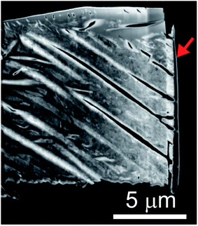 | ||
| Fig. 9 Dark-field TEM image of the rhombohedral Y2(SO4)3 specimen cut out from the rhombohedral Y2(SO4)3 particle by FIB processing. Rhombohedral Y2(SO4)3 made from Y2(SO4)3·8H2O by heating at 200 °C for 1 hour in air. Vertical black few-hundred-nm-thick layer at the right edge of the sample indicated by the red arrow is deposited carbon for FIB processing following the same procedure used in ref. 17. | ||
4. Discussion
4.1 Relationships between water insertion mechanisms and reaction temperature ranges: comparison of rhombohedral Y2(SO4)3 and β-La2(SO4)3
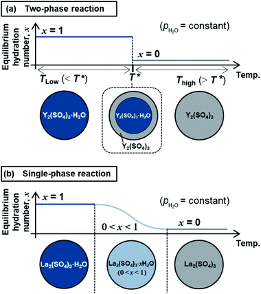
The high-temperature hydration reaction of rhombohedral Y2(SO4)3·xH2O (x = 0 or ∼1) likely proceeds by water insertion into the crystal lattice (see Section 3.1.1). This reaction is similar to the hydration reaction of β-La2(SO4)3·xH2O (0 ≤ x ≤ 1) (monoclinic).15 However, their water insertion mechanisms differ. Regarding β-La2(SO4)3·xH2O, the hydration number x changes continuously with maintaining a single-phase nature during the dehydration/hydration reactions. In contrast, the high-temperature hydration reaction of rhombohedral Y2(SO4)3 is a “two-phase reaction” because two different phases (rhombohedral Y2(SO4)3 and rhombohedral Y2(SO4)3·H2O) co-exist during the dehydration at 110 °C (see Section 3.1.1 and Fig. 2). Fig. 10 schematically depicts the dehydration processes of (a) the two-phase reaction and (b) the “single-phase reaction”. The two-phase reaction proceeds as the ratio of hydrated and dehydrated phases changes, while the single-phase reaction proceeds as the hydration number of the single solid phase continuously decreases. A two-phase reaction proceeds at a single equilibrium temperature in principle. Thus, the two-phase reaction with a sufficiently fast reaction rate can complete reversible reactions in a narrow temperature range (e.g., rhombohedral Y2(SO4)3·xH2O (x = 0 ⇄ ∼1): 80–130 °C at a rate of 1 °C min−1). On the other hand, a single-phase reaction advances with changing the hydration number and the equilibrium temperature continuously in principle. Even if the reaction rate is fast enough, the reaction temperature range broadens (e.g., β-La2(SO4)3·xH2O: 80–250 °C at a rate of 1 °C min−1 (ref. 15)). Therefore, the two-phase reaction with a sufficiently fast reaction rate is preferred for the TCHS system as the required temperature range for reaction completion narrows.4.2 Applicability of rhombohedral Y2(SO4)3 as a TCHS material
Based on the T–pH2O map (Fig. 6), we consider an application of several reactions of rhombohedral Y2(SO4)3 to chemical heat pumps to upgrade thermal energy. The application employs an apparatus consisting of a reactor containing rhombohedral Y2(SO4)3 and an evaporator containing water. In the heat releasing step, saturated water vapor is transported from the evaporator to the reactor and rhombohedral Y2(SO4)3 is hydrated. Here, the temperature lift (the temperature difference between the evaporator and the reactor) should ideally be equal to the difference between the dew point of water and the equilibrium temperature of the hydration reaction at a constant pH2O. The equilibrium temperatures, the temperature lifts attained by reactions A, B, C, and D shown in Fig. 6 are represented by the temperature differences between the saturation vapor pressure line and the broken lines A, B, C, and D at a constant pH2O (Fig. 6). As can be seen, reaction D (high-temperature reaction: Y2(SO4)3/Y2(SO4)3·H2O) works similarly to the hydration reaction of CaSO4 in terms of the temperature lift. Reaction C (Y2(SO4)3·xH2O/Y2(SO4)3·3H2O) may also be utilized under high pH2O (> ∼0.08 atm). On the other hand, using the two-step reaction of C and D is disadvantageous in that they output heat at different temperatures which leads to a large temperature drop against stored heat. The reactions A (Y2(SO4)3·xH2O/Y2(SO4)3·8H2O) and B (Y2(SO4)3·3H2O/Y2(SO4)3·8H2O) may not be suitable for practical applications due to the small temperature lift (approximately 10 °C).We also discuss in terms of heat storage density. The standard enthalpy change of the high-temperature dehydration reaction of rhombohedral Y2(SO4)3·H2O (reaction D) was estimated by a van't Hoff plot. The relationship between pH2O and the equilibrium temperature of the reaction was assessed by TG measurements on rhombohedral Y2(SO4)3·H2O under four different pH2O (ESI-2†). Fig. 11 shows the van't Hoff plot constructed from the equilibrium temperatures and pH2O. From the slope of the approximated straight line, the estimated standard enthalpy change ΔH° of rhombohedral Y2(SO4)3·H2O is 46 kJ (mol-H2O)−1 or 99 kJ (kg-hydrate)−1. The small gravimetric standard enthalpy change is attributed to the small hydration water content, i.e. the mass change with reaction D, equal to 3.72 mass%.
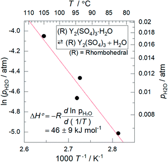 | ||
| Fig. 11 Van't Hoff plot for the high-temperature reaction of rhombohedral Y2(SO4)3·H2O. The equilibrium temperatures T are the estimated values from the TG measurements under four different pH2O (ESI-2†). Because rhombohedral Y2(SO4)3·H2O dehydrates/hydrates via a two-phase reaction, the equilibrium temperature of the reaction (high-temperature reaction) should be a single temperature at each pH2O. | ||
However, if the additional hydration reaction C with 10.3 mass% of mass change is utilized, a larger heat storage capacity is expected although the ΔH°/kJ (kg-hydrate)−1 of Y2(SO4)3·3H2O is not measured. Note that, among the dehydration/hydration reaction systems having similar equilibrium temperatures, the magnitude of ΔH°/kJ (kg-hydrate)−1 dominantly depends on the mass change. This is because the ΔH°/kJ (mol-H2O)−1 of dehydration reaction is approximately proportional to the equilibrium temperature.27 See (ESI-4)† for the relationship between the ΔH° and the equilibrium temperature. Thus, the mass change with the dehydration/hydration reaction is an indicator to simply evaluate the magnitude of the ΔH°/kJ (kg-hydrate)−1.
Here, the gravimetric energy densities of Y2(SO4)3·3H2O and Y2(SO4)3·H2O are compared with other materials. The ΔH° or mass change of Y2(SO4)3·3H2O (10.4 mass%) and Y2(SO4)3·H2O (99 kJ (kg-hydrate)−1, 3.72 mass%) is significantly lower than other salt hydrates with larger hydration numbers or with lower mass, for example, MgSO4·6H2O (1395 kJ (kg-hydrate)−1, 47.3 mass%),5 CaCl2·6H2O (1649 kJ (kg-hydrate)−1, 49.3 mass%),28 Na2S·5H2O (1784 kJ (kg-hydrate)−1, 53.6 mass%),11 and LiOH·H2O (1440 kJ (kg-hydrate)−1, 42.9 mass%).20 Compared with these salt hydrates, an advantage of Y2(SO4)3 system is the ease of handling since neither of aggregation due to the melting or deliquescence or skin formation covering the bulk particles has been confirmed in the hydration/dehydration reaction process. Therefore, Y2(SO4)3 system may be available for TCHS usage without developing composite materials with porous matrix and, in this respect, similar to CaSO4·0.5H2O and β-La2(SO4)3·H2O. The values of ΔH° and the mass change of Y2(SO4)3·3H2O or Y2(SO4)3·H2O are comparable to those of CaSO4·0.5H2O (240 kJ (kg-hydrate)−1 (ref. 26) and 6.21 mass%) and those of β-La2(SO4)3·H2O (156 kJ (kg-hydrate)−1 (ref. 15) and 3.08 mass%).
For TCHS application, heat output rate is also important but the performance of rhombohedral Y2(SO4)3 has never been evaluated yet. Regarding the hydration reaction rate shown in Fig. 3, the hydration reaction with hydration number change x of 1–3 completed within tens of minutes and that with x = ∼6 completed within 3 hours. These hydration reaction rates are comparable to those reported in the hydration of other salts, i.e. MgSO4,5 Na2S,11 β-La2(SO4)3,17 and CaCl2.28
5. Conclusion
We examine the hydration/dehydration of rhombohedral Y2(SO4)3 and their potential as a TCHS material by cyclic TG, high-temperature XRD, isothermal TG, isothermal hydration treatments, nitrogen gas adsorption, optical microscope observations, and TEM observations. TG measurements revealed that rhombohedral Y2(SO4)3 can hydrate/dehydrate reversibly below 130 °C with relatively small thermal hysteresis (less than 50 °C) and large change in hydration water content (above 10 mass%). Rhombohedral Y2(SO4)3 was found to be a favorable material in terms of the reaction temperature and the reaction behavior. The hydration reaction of rhombohedral Y2(SO4)3 proceeds via at least two steps: the high-temperature reaction at 80–130 °C and the low-temperature reaction at 30–100 °C in 0.02 atm of pH2O. The high-temperature hydration reaction proceeds by water insertion into rhombohedral Y2(SO4)3 to form rhombohedral Y2(SO4)3·H2O with only minor changes in the host crystal structure. In the low-temperature hydration reaction, rhombohedral Y2(SO4)3·H2O further hydrates to rhombohedral Y2(SO4)3·xH2O (x > 1) while maintaining the host structure. There is a possibility that rhombohedral Y2(SO4)3·xH2O has a nonstoichiometric hydration number x. At lower temperature (at most 27 °C in 0.02 atm of pH2O), it finally hydrates to Y2(SO4)3·8H2O which has a different crystal structure. Furthermore, another intermediate hydrate Y2(SO4)3·3H2O is formed in the hydration reaction under relatively high pH2O (>0.08 atm) and intermediate temperature.Regarding the application of rhombohedral Y2(SO4)3 to thermochemical heat pumps for energy upgrades, the hydration of rhombohedral Y2(SO4)3 to rhombohedral Y2(SO4)3·H2O can be used in the same manner as an existing candidate material CaSO4·0.5H2O in terms of reaction temperature and pH2O. However, the standard enthalpy change ΔH° of the dehydration of rhombohedral Y2(SO4)3·H2O (46 kJ mol−1) is not sufficient. The hydration of rhombohedral Y2(SO4)3·xH2O to Y2(SO4)3·3H2O (hydration water content: 11.6 mass% anhydrous basis) or Y2(SO4)3·8H2O (hydration water content: 30.9 mass% anhydrous basis) enables a larger change in the hydration number and thereby heat storage density, which is characteristic of this reaction system. Concerning the magnitude of the temperature lift on the practical use, the hydration to form Y2(SO4)3·3H2O may be available but that to form Y2(SO4)3·8H2O is not suitable since the temperature lift is as small as approximately 10 °C.
Finally, microstructure formed during the dehydration reaction from Y2(SO4)3·8H2O to rhombohedral Y2(SO4)3 was investigated. The estimated surface area of rhombohedral Y2(SO4)3 is 7 m2 g−1 while that of the original Y2(SO4)3·8H2O is significantly smaller (0.05 m2 g−1). Correspondingly, rhombohedral Y2(SO4)3 has a fine microstructure with crevices and voids at intervals of a-few-micrometers. Such a fine microstructure is formed by initial dehydration reaction from Y2(SO4)3·8H2O and expected to enhance the dehydration/hydration reaction rates. If the microstructure size can be further improved in the synthesis of rhombohedral Y2(SO4)3, a much faster hydration rate is expected.
Conflicts of interest
There are no conflicts to declare.Acknowledgements
We are grateful to Kenji Kazumi for the FIB processing, TEM observations, and discussion. We would also like to thank Kazuaki Toyoura for valuable discussion. This work was supported by a JSPS Grant-in-Aid for Young Scientists (B) Grant Number 17K17821 and Grant-in-Aid for JSPS Fellows Grant Number 19J15085.Notes and references
- P. Pardo, A. Deydier, Z. Anxionnaz-Minvielle, S. Rougé, M. Cabassud and P. Cognet, Renewable Sustainable Energy Rev., 2014, 32, 591–610 CrossRef CAS.
- T. Yan, R. Z. Wang, T. X. Li, L. W. Wang and I. T. Fred, Renewable Sustainable Energy Rev., 2015, 43, 13–31 CrossRef CAS.
- L. André, S. Abanades and G. Flamant, Renewable Sustainable Energy Rev., 2016, 64, 703–715 CrossRef.
- L. Okhrimenko, L. Favergeon, K. Johannes, F. Kuznik and M. Pijolat, Thermochim. Acta, 2017, 656, 135–143 CrossRef CAS.
- V. Essen, H. Zondag, J. Gores, L. Bleijendaal, M. Bakker, R. Schuitema, W. Helden, Z. He and C. Rindt, J. Sol. Energy Eng., 2009, 131, 041014 CrossRef.
- S. Hongois, F. Kuznik, P. Stevens and J.-J. Roux, Sol. Energy Mater. Sol. Cells, 2011, 95, 1831–1837 CrossRef CAS.
- K. N'Tsoukpoe, H. Rammelberg, A. Lele, K. Korhammer, B. Watts, T. Schmidt and W. Ruck, Appl. Therm. Eng., 2015, 75, 513–531 CrossRef.
- M. Kubota, S. Matsumoto, H. Matsuda, H. Huang, Z. He and X. Yang, Adv. Mater. Res., 2014, 953, 757–760 Search PubMed.
- S. Li, H. Huang, X. Yang, Y. Bai, J. Li, N. Kobayashi and M. Kubota, Appl. Therm. Eng., 2018, 128, 706–711 CrossRef CAS.
- M. Kubota, S. Matsumoto and H. Matsuda, Appl. Therm. Eng., 2019, 150, 858–863 CrossRef CAS.
- R. Boer, W. Haije and J. Veldhuis, Thermochim. Acta, 2003, 395, 3–19 CrossRef.
- A. Jong, F. Trausel, C. Finck, L. Vliet and R. Cuypers, Energy Procedia, 2014, 48, 309–319 CrossRef.
- J.-H. Lee, H. Ogura and S. Sato, Appl. Therm. Eng., 2014, 63, 192–199 CrossRef CAS.
- Y. Shiren, M. Masuzawa and N. Kobayashi, WASET. International Journal of Environmental, Chemical, Ecological, Geological and Geophysical Engineering, 2015, vol. 9, pp. 803–807 Search PubMed.
- N. Hatada, K. Shizume and T. Uda, Adv. Mater., 2017, 29, 1606569/1–1606569/6 CrossRef PubMed.
- K. Toyoura, H. Tai, N. Hatada, K. Shizume and T. Uda, J. Mater. Chem. A, 2017, 5, 20188–20194 RSC.
- K. Shizume, N. Hatada, K. Toyoura and T. Uda, J. Mater. Chem. A, 2018, 6, 24956–24964 RSC.
- H. Voigtländer, B. Winkler, W. Depmeier, K. Knorr and L. Ehm, in Host–Guest Systems Based on Nanoporous Crystals, ed. F. Laeri, F. Schüth, U. Simon and M. Wark, John Wiley & Sons, New Jersey, 1st edn, 2006, ch. 3, pp. 280–305 Search PubMed.
- R. Perret, B. Rosso and J. Loriers, Bull. Soc. Chim. Fr., 1968, 7, 2698–2699 Search PubMed.
- M. Kubota, S. Matsumoto and H. Matsuda, Appl. Therm. Eng., 2019, 150, 858–863 CrossRef CAS.
- B. Rosso, R. Perret and J. Lories, C. R. Hebd. Seances Acad. Sci., 1968, 267, 379–382 CAS.
- W. Wendlandt, J. Inorg. Nucl. Chem., 1958, 7, 51 CrossRef CAS.
- D. Bernhardt, I. Reilly and J. Mineral, Commodity Summaries 2019, Department of the Interior (DOI), U.S. Geological Survey (USGS), Reston, VA, USA, 2019 Search PubMed.
- K. Shizume, N. Hatada, K. Toyoura, H. Tai, S. Yasui and T. Uda, Presented in part at the IMPRES2019, Kanazawa, October, 2019 Search PubMed.
- S. Mills, V. Petrříčicek, A. R. Kampf, R. Herbst-Imer and M. Raudsepp, J. Solid State Chem., 2011, 184, 2322–2328 CrossRef CAS.
- S. Lee, H. Matsuda and M. Hasatani, Kagaku Kogaku Ronbunshu, 1986, 12, 75–82 CrossRef CAS.
- S. Kiyabu, J. Lowe, A. Ahmed and D. Siegel, Chem. Mater., 2018, 30, 2006–2017 CrossRef CAS.
- F. Trausel, A.-J. Jong and R. Cuypers, Energy Procedia, 2014, 48, 447–452 CrossRef CAS.
Footnotes |
| † Electronic supplementary information (ESI) available. See DOI: 10.1039/d0ra02566f |
| ‡ The major problems of these salt hydrates are described below. MgSO4·nH2O (n = 0–7): shape instability due to the melting of the salt which occurs during dehydration of MgSO4·7H2O to MgSO4·6H2O.5 In addition, the fine powder rapidly forms a skin of the hydrated salt on the surface when it reacts with humid air, which decreases the reaction rate.6 CaCl2·nH2O (n = 0–6): agglomeration of the salt due to partial melting of the salt during the dehydration or a partial formation of a solution of the salt attributed to the hygroscopicity during rehydration, which decreases the reaction rate.7 LiOH·H2O: the low hydration reaction rate of pure LiOH which limits the performance of low-temperature TCHS systems.9,10 Na2S·5H2O: generation of toxic by-product H2S gas by contacting with water.12 CaSO4·0.5H2O: degradation due to phase transformation from CaSO4 (III) to the low-hydration-reactive phase CaSO4 (II) during repetitive dehydration/hydration reaction.13,14 |
| § CaSO4·0.5H2O is also known to dehydrate and rehydrate by deinsertion and insertion of H2O guest molecules into the sulfate host lattice.18 |
| ¶ The crystal structure of Y2(SO4)3·3H2O is considered to be the same as that of Yb2(SO4)3·3H2O reported by Mills et al.25 The XRD pattern of Y2(SO4)3·3H2O shown in Fig. 5 as orange inverted triangles was estimated by adjusting only the diffraction angles of XRD peaks of Yb2(SO4)3·3H2O while the peak intensities were left as is. |
| || Focusing only on condensed phases in the Y2(SO4)3–H2O pseudo-binary system, the degree of freedom F is represented as follows: F = C − P + 2 = 4 − P, where C is the number of independent components and P is the number of condensed phases. In the case of the isothermal hydration reaction of Y2(SO4)3, the temperature and the total pressure are fixed and the chemical potential of H2O is determined by the water vapor pressure of gas phase equilibrated with the Y2(SO4)3–H2O system. Then the degree of freedom becomes F = 1 − P. Because the F should be larger than zero, the number of the solid phase should be 1 at most. |
| ** We did not conduct TEM observations on Y2(SO4)3·8H2O due to the difficulty with sample preparation. The dehydration reaction of Y2(SO4)3·8H2O proceeded even under a vacuum at room temperature on FIB processing for sample preparation. |
| This journal is © The Royal Society of Chemistry 2020 |

