 Open Access Article
Segregated poly(arylene sulfide sulfone)/graphene nanoplatelet composites for electromagnetic interference shielding prepared by the partial dissolution method†
Jia-Cao Yang a,
Xiao-Jun Wang*b,
Gang Zhangb,
Zhi-Mei Weib,
Sheng-Ru Longb and
Jie Yangbc
aCollege of Polymer Science & Engineering, Sichuan University, Chengdu, 610065, China
bAnalytical & Testing Center, Sichuan University, Chengdu, 610064, China. E-mail: wangxj@scu.edu.cn
cState Key Laboratory of Polymer Materials Engineering, Sichuan University, Chengdu, 610065, China
First published on 2nd June 2020
Abstract
Segregated conductive polymer composites have been proved to be outstanding electromagnetic interference shielding (EMI) materials at low filler loadings. However, due to the poor interfacial adhesion between the pure conductive filler layers and segregated polymer granules, the mechanical properties of the segregated composites are usually poor, which limit their application. Herein, a simple and effective approach, the partial dissolution method, has been proposed to fabricate segregated poly(arylene sulfide sulfone) (PASS)/graphene nanoplatelet (GNP) composites with superior EMI shielding effectiveness (SE) and high tensile strength. Morphology examinations revealed that the GNPs were restricted in the dissolved outer layer by the undissolved cores, and there was a strong interaction between the PASS/GNP layer and the pure PASS core. The resultant PASS/GNP composites showed excellent electrical conductivity (60.3 S m−1) and high EMI SE (41 dB) with only 5 wt% GNPs. More notably, the tensile strength of the PASS/GNPs prepared by partial dissolution reached 36.4 MPa, presenting 136% improvement compared to that of the conventional segregated composites prepared by mechanical mixing. The composites also exhibited high resistance to elevated temperatures and chemicals owing to the use of the special engineering polymer PASS as a matrix.
1. Introduction
The prosperity of the electromagnetic technology has brought us great convenience, but the accompanying electromagnetic interference and pollution have also become serious problems. Significant attention has been given to the development of electromagnetic interference (EMI) shielding materials.1–3 Compared to the conventional metal-based EMI shielding materials, unique characteristics such as light weight, low cost, corrosion resistance and good processability make conductive polymer composites (CPCs) a promising alternative.3–6 It is widely recognized that high electrical conductivity is a prerequisite to achieve high EMI shielding. To reach the minimum EMI shielding effectiveness (SE) required for commercial applications, i.e., 20 dB, which means that 99% of the incident electromagnetic wave is shielded, the electrical conductivity of CPCs must exceed 1 S m−1.7 Such high electrical conductivity needs the formation of a conductive filler network. For CPCs prepared by the conventional melt or solution mixing method, where the fillers randomly disperse in the matrix, a large amount of conductive fillers is needed for the formation of the filler network. For instance, Liu et al.8 prepared a carbon nanotube (CNT)/polyurethane (PU) composite exhibiting an average EMI SE of 17 dB at 20 wt% CNTs. Ling et al.9 introduced graphene into polyetherimide (PEI), revealing an EMI SE of 21 dB with a graphene loading of 10 wt%. An enhanced EMI SE of 29 dB was obtained at the cost of an extremely high graphene loading of 30 wt%.10 While improving EMI SE, a high filler content would inevitably increase the cost and decrease both the processability and mechanical properties.Recently, CPCs with a segregated structure, where the conductive fillers are restricted at the interface rather than uniformly distributed in the whole matrix, have been proved to promote the formation of a conductive network, reduce the threshold and boost the EMI SE in many published reports in the literature.11–18 Gelves et al.12 synthesized segregated polystyrene (PS)/Cu nanowire composites, which exhibited EMI SE levels of 26 and 42 dB at 10 and 13 wt%, respectively. Jia et al.14 compared the EMI SE performances of segregated and conventional polyethylene (PE)/CNTs. The results showed that the EMI SE of the segregated composites was 47.1 dB with 5.0 wt% CNTs, which was 14.7 dB higher than that of the conventional ones. Yan et al.15 compounded reduced graphene oxide (rGO) with PS and obtained composites with a segregated structure via high pressure solid-phase compression; they reported an EMI SE as high as 45.1 dB with only 3.47 vol%.
Nevertheless, the dense conductive layer at the interface blocks the molecular diffusion between adjacent polymer granules, leading to poor mechanical performances, which handicap the practical applications of segregated CPCs.19 Some researchers19–24 applied another polymer component as the carrier for the conductive fillers, and the conductive filler-rich phase acted as a binder between the segregated polymer granules to improve the mechanical properties. For example, Pang20 introduced PE as a binder to the segregated ultrahigh molecular weight polyethylene (UHMWPE)/CNTs and achieved a 34.2% improvement in tensile strength. Jia21 prepared CNTs/UHMWPE/ethylene vinyl acetate (EVA) segregated composites with EVA as the filler carrier, and the tensile strength reached 23 MPa. This method generally takes advantage of the difference between the melt or dissolution behavior of two polymer components: one of the polymers is melted or dissolved to mix with the fillers, while the other one keeps a solid (or quasi-solid) state to prevent the migration of fillers to this phase. Thus, the interfacial adhesion between the two polymer components is inferior. It is still a challenge to prepare segregated CPCs with both excellent electrical properties and mechanical performances for EMI shielding.
Improving the interfacial adhesion between the segregated phases and the conductive network is the key factor for high mechanical strength EMI shielding composites.19,20 Inspired by the dissolution process of polymer granules,25,26 the mechanical properties of segregated CPCs may be solved by the partial dissolution method. By controlling the dissolution process, the polymer granule is partially dissolved: the dissolved outer layer is mixed with the conductive fillers, while the undissolved core retains its solid state to prevent the migration of fillers into this phase to form a segregated structure. In this way, there would be abundant penetration and entanglement between the conductive network and segregated undissolved core, leading to excellent interactions between these two region.27,28 The composite prepared by the partial dissolution method is expected to possess high mechanical properties, as well as excellent EMI shielding effectiveness.
In addition, the recent research studies on CPCs for EMI shielding have mainly focused on general polymers such as PU,8 PS,10,12,15 PLA19,23 PE,14,16,18,20 and polypropylene (PP).22 Although they possess considerable EMI shielding performance, the intrinsic shortcomings of these general polymers (e.g., poor flame retardance, inferior dimensional stability and low harsh-environment resistance) hinder the application of CPCs in aerospace and other high-technology fields.
In the current study, the poly(arylene sulfide sulfone) (PASS)/graphene nanoplatelet (GNP) composites were prepared by the abovementioned partial dissolution method. As a structurally modified species of poly(phenylene sulfide) (PPS), PASS is a kind of special engineering polymer that can provide outstanding thermal and chemical resistance29–35 for the EMI shielding CPCs. The final PASS/GNP composites exhibited an ultralow percolation threshold, high EMI SE, elevated mechanical properties and excellent resistance to high temperature and chemicals. Therefore, the partial dissolution method is a promising method for high-performance CPCs with segregated structure for EMI shielding.
2. Experimental
2.1 Materials
PASS with an inherent viscosity of 0.42 dL g−1 were synthesized in our laboratory.29 GNPs (purity > 99%) were supplied by The Sixth Element Co., Ltd (Changzhou, China). N-Methyl pyrrolidone (NMP, AR grade), hydrochloric acid, sodium hydroxide, toluene, tetrahydrofuran (THF) and acetone were provided by the Chengdu Kelong Chemical Reagent Factory (China). High-temperature resistant silver paste was purchased from the Jiangsu Shenggelu New Materials Company (China).2.2 Fabrication of PASS/GNP composites
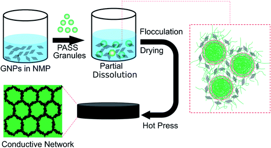
The schematic representation for fabricating the PASS/GNP composites by the partial dissolution method is illustrated in Fig. 1. GNPs were suspended in NMP and subjected to ultrasonication and mechanical stirring for 2 hours for homogenous dispersion. Then, PASS granules were added to the suspension with stirring. To ensure the core of the granules kept its solid state, the temperature was fixed at room temperature and the dissolution process was terminated after 30 min. After that, the mixture was flocculated using distilled water, and dried in a blast oven (100 °C) for 12 hours. Finally, the dried mixture was compressed into samples for the EMI shielding and mechanical tests at 240 °C and 2.5 MPa for 10 min after a preheating step of 10 min.For comparison, the mechanical mixing method18 was also adopted to prepare the PASS/GNP composites. GNPs-warped PASS granules were obtained after being mechanically mixed in a high-speed mixer for 5 min at a speed of 24![[thin space (1/6-em)]](https://www.rsc.org/images/entities/char_2009.gif) 000 rpm, and hot-pressed at 240 °C and 2.5 MPa for 10 min after a preheating step of 10 min into samples.
000 rpm, and hot-pressed at 240 °C and 2.5 MPa for 10 min after a preheating step of 10 min into samples.
The resulting PASS/GNP composites prepared by partial dissolution and by mechanical mixing are abbreviated as PD-x and M-x, respectively, where x represents the weight fraction percentage of GNPs in the composites.
2.3 Characterization
For optical microscopy (OM) observations, the composite specimens were cut into 10 μm-thick pieces using a microtome and observed with an Olympus BX51 microscope equipped with a digital camera (Olympus C-4000 ZOOM). For the scanning electronic microscopy (SEM) observation, the fracture surfaces of the cryo-fractured samples and samples from the tensile test were sputter-coated with gold and observed using a field emission SEM (SEM & EDS Inspector F, USA) at an accelerating voltage of 20 kV.A digital multimeter (17B, Fluke, USA) was applied to measure the electrical resistance of the composites, and the electrical conductivities were calculated based on the resistance and size of the samples. Before the test, both ends of the rectangular specimens were coated with a thin layer of silver paste and cured at 140 °C for 2 hours, in accordance with the product guidance, to eliminate the contact resistance. At least five specimens were tested and the averaged results were calculated. To study the high-temperature resistance of the PASS/GNP composites, the specimens were placed in a temperature-tunable environment chamber.
EMI SE measurements were carried out on the Agilent N5230 vector network analyzer (USA) at room temperature in the frequency range of 8.2–12.4 GHz. The specimens with a 2 mm thickness and 12 mm diameter were used for the measurement. The absorbed power (A), reflected power (R), transmitted power (T), absorption shielding (SEA), reflection shielding (SER) and EMI SE (SET) were calculated by the scattering parameters.14
The tensile tests of the samples were determined using at least five specimens for each sample with a universal test instrument (E45, MTS, China) at a gauge length of 40 mm and a constant crosshead speed of 5 mm min−1.
To evaluate the chemical resistance of the PASS/GNP composites, the specimens for the EMI SE test were immersed in different chemical liquids, including 1 M hydrochloric acid, 1 M sodium hydroxide aqueous solution, toluene, THF, acetone and NMP, at room temperature for 48 h and rinsed by ethanol and dried in an oven. The EMI SEs of these specimens before and after liquid treatment were tested and compared. The chemical resistance test was carried out on three samples for one kind of liquid for the parallel test.
3. Results and discussion
3.1 Morphology
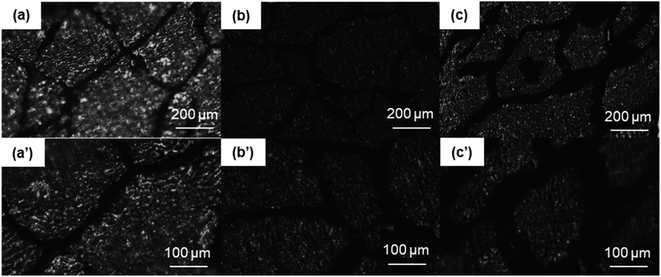
The OM images of the PASS/GNP composites are shown in Fig. 2. The distribution of GNPs in the composites can be easily identified due to the light transmittance difference between the GNPs and PASS. As observed, the GNP-enriched phase (dark region) is distinctly segregated from the GNP-scarce phase (bright region) in both M-x composites and PD-x composites. This observation is in line with other studies on segregated CPCs,14,22 suggesting the successful preparation of the segregated structure by the partial dissolution method. Mechanical mixing has become a common method for segregated CPCs, and its mechanism has been reported in a large quantity.16–18 During the mechanical mixing process, the GNPs were adsorbed onto the surface of the PASS granules. In the subsequent hot-pressing stage, as the temperature was around the Tg of PASS,34 the movement of the molecular chains was confined so that the GNPs were prevented from penetrating into the PASS region. Instead, they were selectively distributed at the interface between the PASS phases. Although the PD-x composites showed similar OM features to the M-x composites, the segregated structure in the PD-x composites was different from the segregated structure of the M-x composites. Rather than just adsorbing onto the surface of the PASS granules, GNPs mixed with the dissolved outer layer of the PASS granules. In the hot-pressing procedure, GNPs were confined in the outer layer and kept out of the undissolved core due to the low temperature. To some extent, the preparation of the segregated composites via partial dissolution is similar to the method of introducing a second polymer component. For example, Jia21 prepared segregated CNTs/EVA/UHMWPE composites by dissolving EVA in xylene and mixing it with CNTs, followed by the introduction of insoluble UHMWPE particles as the segregated phase. Comparing our research with his case, the dissolved outer layer of the polymer granules corresponded to the soluble EVA and the undissolved core corresponded to the insoluble UHMWPE. In general, the difference between the segregated structures in M-x and PD-x was that the dark continuous network and bright segregated region in the M-x composites were pure GNPs and intact PASS granules, whereas those in the PD-x composites were GNPs/PASS and remaining PASS granule cores, respectively. Interconnected conductive networks had already developed in composites with 1 wt% GNPs. As the GNP content increased to 5 wt%, the PASS/GNP network became denser, indicative of the perfect conductive network.To further elucidate the details of the morphology of the PASS/GNP composites, SEM observations were conducted and the results are shown in Fig. 3. A big difference was revealed on the fracture surface of the composites prepared by mechanical mixing and partial dissolution. Fig. 3(a) clearly shows the selective distribution in a specific continuous path to form the conductive network, in accordance with the OM results. A higher magnification observation verifies the ideal interface between the segregated phase and continuous network because of the formation mechanism. On the other hand, the M-5 case was totally different. M-5 showed a rugged fracture surface with a faceted microstructure due to the detachment of the PASS granules. This rugged fracture surface of the segregated composites has also been reported by Ryu's research on polymethyl methacrylate (PMMA)/CNT composites36 and Shahzad's research on rGO/PS.37 In a larger magnification image, as shown in Fig. 3(b′), the surface is covered by GNPs, indicating the poor interaction between the PASS granules.
3.2 Electrical conductivity and EMI shielding performance
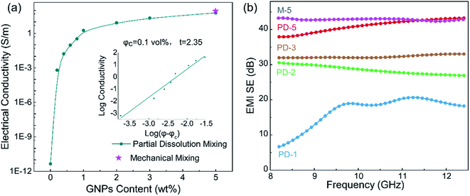
Fig. 4(a) presents the electrical conductivity of the PASS/GNP composites. The conductivity of PD-0.2 reached 6.4 × 10⁻⁴ S m−1, compared to the conductivity of pure PASS (4.48 × 10⁻¹² S m−1), exhibiting a sharp increase and demonstrating the formation of a percolation network at such low GNPs-loading. With increasing addition of GNPs, the electrical conductivity further increased. 1 wt% GNPs endowed PD-1 with an electrical conductivity of 1.83 S m−1, exceeding the target value (1 S m−1) for the commercial EMI shielding application.7 When 5 wt% GNPs were introduced, the electrical conductivity of PD-5 reached 60.3 S m−1, which is comparable to composites prepared by mechanical mixing (73.8 S m−1). GNPs in segregated composites were not uniformly distributed throughout the whole PASS matrix, but were instead confined at the interface so that they could make contact and overlap more frequently to form a conductive network, leading to the enhancement of the utilization of GNPs and high electrical conductivity. As we mentioned in the morphology section, the conductive network is composed of pure GNPs in M-x and GNPs/PASS in PD-x. Doping of the polymer in the conductive network impeded the contact and overlapping of GNPs with each other, leading to a slight reduction of the electrical conductivity of PD-5 compared to M-5. This decrease trend of the conductivity because of the doping of the polymer in the conductive network is consistent with the literature In Jia's research14 on the segregated PE/CNT composites, the electrical conductivity of the composites had PE in the conductive network is 74% lower than that of composites without PE in conductive network. Wu22 compared the electrical performance of the segregated composites with and without a polymer in the conductive network, and the electrical conductivity is 86.3 S m−1 for the former and 117.0 S m−1 for the latter. The classic percolation theory, σ = σ0(φ − φc)t, was introduced to evaluate the relationship between the content of GNPs (φ) and electrical conductivity (σ), where σ0 is a constant related to the intrinsic conductivity of GNPs, φc is the percolation threshold of the composites, and t is a parameter related to the dimensionality of the conductive network.10 As shown in the insert in Fig. 4(a), the fitted φc is 0.1 vol%, showing the high efficiency of the segregated structure. High efficiencies in segregated structures have been reported in numerous studies in the literature. Zhai38 prepared CNTs/UHMWPE composites with a segregated structure and random distribution structure, and the percolation of the former was 0.13 vol%, which was just one-thirtieth of that of the latter. Jia21 also reported a similar result that the percolation of composites with uniform filler-distribution was tenfold that of the segregated composites. The obtained t was 2.35, indicating the formation of a three-dimensional GNP conductive network.39 The enhanced electrical conductivity of the PASS/GNP composite prepared by partial dissolution method demonstrates its potential application in EMI shielding.Fig. 4(b) shows the EMI SE value of the PASS/GNP composites over the X band as a function of the GNP content. At only 1 wt% addition of GNPs, PD-1 showed an average EMI SE value of 16.9 dB, and the EMI SE value in the frequency range between 10.9 GHz and 11.6 GHz surpassed 20 dB, already exceeding the target EMI SE value (20 dB). Consistent with the electrical conductivity trend, the EMI SE value of the PD-x composites also increased with the increased GNP content. The average EMI SE values of PD-2, PD-3 and PD-5 were 28.5 dB, 32.3 dB and 41.0 dB, which meant 99.859%, 99.941% and 99.992% of the incident electromagnetic wave was shielded, respectively. With the exception of PD-1, the EMI SE values of PD-2, PD-3 and PD-5 all exhibited weak frequency dependence, making them applicable over a wide spectrum. The frequency dependence of PD-1 may be due to its low GNP content, which resulted in the imperfect arrangement of the conductive network as reported by Ren.40 The EMI SE value of PD-5 was comparable to that of M-5 (44.1 dB), demonstrating that the partial dissolution method is a promising approach for the preparation of segregated CPCs for EMI shielding application.
To clarify the shielding mechanism of the PD-x composites, SER and SEA were separated from the total shielding effectiveness (SET) and the results are displayed in Fig. 5(a). It can be seen that, except for 7.1 dB from PD-1, the SER values of PD-2, PD-3 and PD-5 all kept at low values below 4 dB. Conversely, the SEA values substantially increased with increasing GNP content. The SEA values for PD-2, PD-3 and PD-5 accounted for at least 88% of their SET, indicating an adsorption-dominant shielding mechanism, which avoids the secondary pollution triggered by the electromagnetic wave reflected at the shielding material surface.
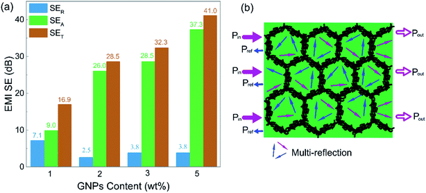 | ||
| Fig. 5 (a) Comparison of the average SER, SEA and SET of PD-x composites; (b) schematic of the EMI shielding mechanism of the PD-x composites. | ||
Excellent EMI shielding effectiveness and absorption dominant mechanism are the beneficial properties of the segregated structure. The PASS/GNP conductive network can be regarded as many tiny “electromagnetic cages”18 in the composites. When the electromagnetic waves enter the composite, it will be trapped in the cell-like cage and attenuated through multiple reflections and scattering events, as visually illustrated in Fig. 5(b). The high proportion of the reflection part of PD-1 may be due to the incomplete conductive network at low GNP loading.
3.3 Mechanical properties
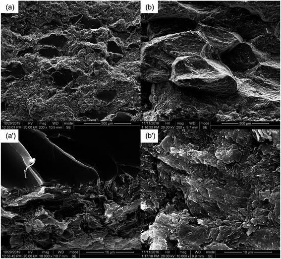
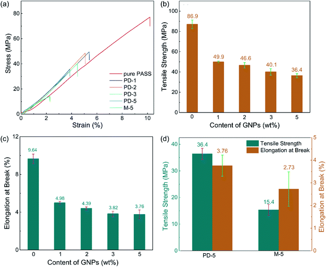
Besides the excellent EMI shielding performance, the partial dissolution method is expected to endow segregated CPCs with high mechanical properties. The mechanical properties of the PASS/GNP composites were tested (Fig. 6). Typical stress–strain curves were plotted, as shown in Fig. 6(a). It can be seen that the stress of all PASS/GNP composites increased linearly with the strain, and there was no yielding behavior, which originates from the rigidity of the PASS matrix. To further exhibit the mechanical performance of the PASS composites with different GNP content, the tensile strength and elongation at break are displayed in Fig. 6(b), (c) and (d). It can be seen that the addition of the GNPs caused a reduction in the tensile strength and elongation at break rather than enhancement, compared to pure PASS. With the addition of 1 wt% GNPs, the tensile strength of PD-1 showed a 42% shrinkage from 86.0 MPa to 49.9 MPa, and the elongation declined from 9.64% to 4.98% (a 48% reduction). In research concentrating on reinforcing the effect of the polymer/nano-filler composites, the key point for high mechanical properties is the good dispersion state of the nano-fillers. If poorly dispersed and forming agglomerates, the nano-fillers would deteriorate rather than improve the mechanical performance, as shown by many highly filled nano-composites.41,42 In the case of the PD-x composites, GNPs were restricted in the dissolved part, contacting and overlapping with each other and forming agglomerates. While endowing high electrical conductivity, these agglomerates also act as defects that deteriorate the mechanical properties. It is noteworthy that more GNPs did not cause a significant reduction of the tensile strength and elongation at break. The tensile strength and elongation at break of PD-5 were 36.4 MPa, and 3.76%, respectively, keeping a relatively high level. Compared with composites prepared by mechanical mixing with the same GNP content (Fig. 6(d)), the mechanical properties of PD-5 showed 136% and 35% increases for the tensile strength and elongation at break, respectively. The better mechanical properties of PD-5 compared to M-5 originate from the difference of the conductive network. In PD-5 composites, the conductive network is PASS/GNPs, while it is pure GNPs in the M-5 composites. Although the existence of polymer hinders the enhancement of conductivity, as mentioned in the electrical conductivity section, it can hold a larger load and lead to higher mechanical properties. The improvement of the mechanical performance of the segregated composites caused by the introduction of a polymer in the conductive network has also been reported previously by Pang20 and Zhai.38To figure out the reasons for the differences of the mechanical performance of composites prepared by partial dissolution and mechanical mixing, SEM observation was employed. The SEM results are presented in Fig. 7. The fracture surface of M-5 (Fig. 7(a)) is characterized by large grooves caused by the detachment of PASS granules, and the amplification in Fig. 7(a′) shows that the surface is covered by GNPs. As shown in Fig. 7(b), the pure PASS region with a smooth fracture section and no GNPs distribution is exposed, indicating that the crack propagates through the undissolved PASS core. The amplification (Fig. 7(b)) reveals the plastic deformation of pure PASS adjacent to the PASS/GNP layer, showing the good stress transfer between the connective conductive network and segregated core.
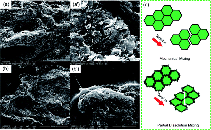 | ||
| Fig. 7 SEM images of the tensile fracture surface of (a and a′) M-5 and (b and b′) PD-5; (c) schematic of the fracture mechanism of the composites upon tensile test. | ||
For a better understanding, a schematic of the microstructure development is illustrated in Fig. 7(c). In the case of composites prepared by mechanical mixing, because of the lack of polymer chain entanglement and the poor adhesion between the pure GNPs layers and PASS granules, the M-x composites are liable to form defects at the interface. These defects evolve into macro-cracks during tensile loading. The PASS granules experienced little deformation and detached easily, resulting in poor mechanical properties. In the composites prepared by partial dissolution, the enhancement mechanism may be doubled. First, it is not the pure GNPs layer but the PASS/GNPs layer that bonds the PASS granules together, which have better mechanical properties. Second, because the PASS in the PASS/GNPs layer and pure PASS core are formed from the partial dissolution of the PASS granule, there is a strong interaction between the PASS/GNP layer and the pure PASS core. With the tensile loaded, the stress is transferred from the PASS/GNP layer to the pure PASS core. The cracks propagate through the core rather than just the continuous PASS/GNPs layer.
As shown in the comparison in Table 1, the segregated PASS/GNP composites prepared by partial dissolution method yielded excellent EMI SE values, as well as high mechanical properties, implying that partial dissolution is a promising method for achieving high-performance CPCs for EMI shielding.
| Matrix | Filler | Content (wt%) | EMI SE (dB) | Thickness (mm) | Preparation method | Tensile strength (MPa) | Reference |
|---|---|---|---|---|---|---|---|
| Natural rubber | CNTs | 10 | 43.7 | 2.6 | Latex mixing | 10.6 | 13 |
| UHMWPE | CNTs | 4.0 | 33 | 2.0 | Mechanical mixing | 43 | 18 |
| EVA/UHMWPE | CNTs | 7.0 | 57.4 | 2.1 | Solution mixing | ∼23 | 21 |
| PP | CNTs | 5.0 | 43.1 | 2.0 | Injection molding | 9.8 | 22 |
| PP | CNTs | 1.0 | ∼33 | 2.2 | High pressure | ∼25 | 43 |
| PEI | CNTs | 4.0 | 34.6 | 2.0 | Microwave sinter | 35.7 | 44 |
| PU | CNTs | 5.0 | 35.3 | 2.0 | Microwave sinter | 11.5 | 45 |
| PU | CNTs | 5.0 | 36.2 | 2.0 | Compaction molding | 4.8 | 45 |
| UHMWPE | Graphite | 15 | ∼28 | 2.0 | Mechanical mixing | 16 | 46 |
| UHMWPE | Graphite/carbon black | 15 | ∼36 | 2.0 | Mechanical mixing | 25.3 | 46 |
| Epoxy | Carbon nanostructure | 1.0 | ∼22 | 1.8 | Compaction molding | ∼7 | 47 |
| PASS | GNPs | 5.0 | 41 | 2.0 | Partial dissolution | 36.4 | This work |
3.4 Environment resistance
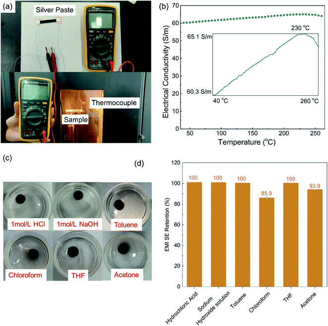
As a high performance polymer, PASS was chosen as the matrix for the harsh environment application. The reliability at high temperatures and chemical exposure was investigated, and the results are shown in Fig. 8. Because testing the EMI SE at a high temperature is beyond the ability of the Agilent N5230 vector network analyzer, the high temperature reliability was evaluated by the electrical conductivity on which EMI SE strongly depends. As can be seen in Fig. 8(b), the electrical conductivity of PD-5 increased gradually (but steadily) and turned to a decreasing trend at 230 °C, which is close to the glass transition temperature of PASS. The temperature elevation intensified the electronic movement and expanded the polymer gap between GNPs, favorable and unfavorable, to the electrical conductivity of the polymer/nano-carbon composites, respectively.48,49 Below 230 °C, the electronic movement intensification played a dominant role and enhanced the electrical conductivity. Exceeding the glass transition temperature, the extent of polymer expansion rose and the gap expansion took over, leading to the reduction of the electrical conductivity. Although it slightly depended on the temperature, the electrical conductivity remained around 62.7 S m−1 within ±3.8% variation, exhibiting excellent reliability at high temperatures.The chemical resistance was evaluated by comparing the EMI SE values of the samples before and after immersion in different chemicals. As presented in Fig. 8(d), the EMI SE value held constant after immersion in 1 M hydrochloric acid, 1 M sodium hydroxide solution, toluene and THF for 48 hours, and showed a slight decrease (6%) for the acetone treatment. Although PASS is soluble to a small extent in chloroform, the EMI SE retention was 86%, which is still a relatively high level. The performances at high temperatures and after chemical treatments demonstrate the potential applications in harsh working conditions as EMI shielding materials, such as applications in aviation and aerospace fields.50,51
4. Conclusion
In this paper, segregated PASS/GNP composites were prepared by the partial dissolution method. Attributed to the segregated structure and strong interaction between the PASS/GNP layer and undissolved core formed during the partial dissolution process, the high mechanical properties were achieved without sacrificing the EMI shielding performance. With the addition of 5 wt% GNPs, the EMI SE value reached 41 dB and the tensile strength was 36 MPa. The characteristics of PASS endowed PASS/GNPs with excellent high temperature resistance and chemical resistance. The electrical conductivity of composites with 5 wt% GNPs remained steady in the range from 60.3 to 65.1 S m−1. After treatment by different chemicals, the retentions of EMI SE were higher than 86%. These properties make the segregated PASS/GNPs a competitive shielding material for use in harsh working environments, particularly for applications in the aviation and aerospace fields.Conflicts of interest
There are no conflicts to declare.Acknowledgements
The authors gratefully acknowledge the financial support from the Jiangsu Provincial Key Research and Development Program (Grant No. BE2019008) and the Natural Science Foundation of China (Grant No. 51573103, 21274094 and 21304060).References
- D. Chung, J. Mater. Eng. Perform., 2000, 9, 350–354 CrossRef CAS.
- D. Chung, Carbon, 2001, 39, 279–285 CrossRef CAS.
- H. Abbasi, M. Antunes and J. I. Velasco, Prog. Mater. Sci., 2019, 103, 319–373 CrossRef CAS.
- M. H. Al-Saleh and U. Sundararaj, Carbon, 2009, 47, 1738–1746 CrossRef CAS.
- J. Luo, L. Wang, X. Huang, B. Li, Z. Guo, X. Song, L. Lin, L.-C. Tang, H. Xue and J. Gao, ACS Appl. Mater. Interfaces, 2019, 11, 10883–10894 CrossRef CAS PubMed.
- J. Gao, J. Luo, L. Wang, X. Huang, H. Wang, X. Song, M. Hu, L.-C. Tang and H. Xue, Chem. Eng. J., 2019, 364, 493–502 CrossRef CAS.
- J.-M. Thomassin, C. Jerome, T. Pardoen, C. Bailly, I. Huynen and C. Detrembleur, Mater. Sci. Eng., R, 2013, 74, 211–232 CrossRef.
- Z. Liu, G. Bai, Y. Huang, Y. Ma, F. Du, F. Li, T. Guo and Y. Chen, Carbon, 2007, 45, 821–827 CrossRef CAS.
- J. Ling, W. Zhai, W. Feng, B. Shen, J. Zhang and W. ge Zheng, ACS Appl. Mater. Interfaces, 2013, 5, 2677–2684 CrossRef CAS PubMed.
- D.-X. Yan, P.-G. Ren, H. Pang, Q. Fu, M.-B. Yang and Z.-M. Li, J. Mater. Chem., 2012, 22, 18772–18774 RSC.
- H. Pang, L. Xu, D.-X. Yan and Z.-M. Li, Prog. Polym. Sci., 2014, 39, 1908–1933 CrossRef CAS.
- G. A. Gelves, M. H. Al-Saleh and U. Sundararaj, J. Mater. Chem., 2011, 21, 829–836 RSC.
- L.-C. Jia, M.-Z. Li, D.-X. Yan, C.-H. Cui, H.-Y. Wu and Z.-M. Li, J. Mater. Chem. C, 2017, 5, 8944–8951 RSC.
- L.-C. Jia, D.-X. Yan, C.-H. Cui, X. Jiang, X. Ji and Z.-M. Li, J. Mater. Chem. C, 2015, 3, 9369–9378 RSC.
- D.-X. Yan, H. Pang, B. Li, R. Vajtai, L. Xu, P.-G. Ren, J.-H. Wang and Z.-M. Li, Adv. Funct. Mater., 2015, 25, 559–566 CrossRef CAS.
- L.-C. Jia, D.-X. Yan, X. Jiang, H. Pang, J.-F. Gao, P.-G. Ren and Z.-M. Li, Ind. Eng. Chem. Res., 2018, 57, 11929–11938 CrossRef CAS.
- L.-C. Jia, Y.-K. Li and D.-X. Yan, Carbon, 2017, 121, 267–273 CrossRef CAS.
- W.-C. Yu, J.-Z. Xu, Z.-G. Wang, Y.-F. Huang, H.-M. Yin, L. Xu, Y.-W. Chen, D.-X. Yan and Z.-M. Li, Composites, Part A, 2018, 110, 237–245 CrossRef CAS.
- K. Zhang, G.-H. Li, L.-M. Feng, N. Wang, J. Guo, K. Sun, K.-X. Yu, J.-B. Zeng, T. Li and Z. Guo, et al., J. Mater. Chem. C, 2017, 5, 9359–9369 RSC.
- H. Pang, D.-X. Yan, Y. Bao, J.-B. Chen, C. Chen and Z.-M. Li, J. Mater. Chem., 2012, 22, 23568–23575 RSC.
- L.-C. Jia, D.-X. Yan, C.-H. Cui, X. Ji and Z.-M. Li, Macromol. Mater. Eng., 2016, 301, 1232–1241 CrossRef CAS.
- H.-Y. Wu, Y.-P. Zhang, L.-C. Jia, D.-X. Yan, J.-F. Gao and Z.-M. Li, Ind. Eng. Chem. Res., 2018, 57, 12378–12385 CrossRef CAS.
- Y.-D. Shi, M. Lei, Y.-F. Chen, K. Zhang, J.-B. Zeng and M. Wang, J. Mater. Chem. C, 2017, 121, 3087–3098 CAS.
- T. Li, L.-F. Ma, R.-Y. Bao, G.-Q. Qi, W. Yang, B.-H. Xie and M.-B. Yang, J. Mater. Chem. A, 2015, 3, 5482–5490 RSC.
- B. A. Miller-Chou and J. L. Koenig, Prog. Mater. Sci., 2003, 28, 1223–1270 CAS.
- J. Koenig, Adv. Mater., 2002, 14, 457–460 CrossRef CAS.
- J. Li, H. Nawaz, J. Wu, J. Zhang, J. Wan, Q. Mi, J. Yu and J. Zhang, Compos. Commun., 2018, 9, 42–53 CrossRef.
- T. Nishino and N. Arimoto, Biomacromolecules, 2007, 8, 2712–2716 CrossRef CAS PubMed.
- J. Yang, H.-D. Wang, S.-X. Xu, G.-X. Li and Y.-J. Huang, J. Polym. Res., 2005, 12, 317–323 CrossRef CAS.
- G. Zhang, H. Ren, D. Li, S. Long and J. Yang, Polymer, 2013, 54, 601–606 CrossRef CAS.
- S. Yuan, J. Wang, X. Li, J. Zhu, A. Volodine, X. Wang, J. Yang, P. Van Puyvelde and B. Van der Bruggen, J. Membr. Sci., 2018, 549, 438–445 CrossRef CAS.
- S. Yuan, J. Wang, X. Wang, S. Long, G. Zhang and J. Yang, Polym. Eng. Sci., 2015, 55, 2829–2837 CrossRef CAS.
- Y. Kong, G. Huang, G. Zhang, X. Wang, S. Long and J. Yang, High Perform. Polym., 2014, 26, 914–921 CrossRef.
- G.-M. Yan, Q. Hu, G. Zhang, H.-H. Ren, J.-H. Lu and J. Yang, J. Appl. Polym. Sci., 2018, 135, 46534 CrossRef.
- Y. Liu, A. Bhatnagar, Q. Ji, J. Riffle, J. McGrath, J. Geibel and T. Kashiwagi, Polymer, 2000, 41, 5137–5146 CrossRef CAS.
- S. H. Ryu, H.-B. Cho, J. W. Moon, Y.-T. Kwon, N. S. A. Eom, S. Lee, M. Hussain and Y.-H. Choa, Composites, Part A, 2016, 91, 133–139 CrossRef CAS.
- F. Shahzad, S. H. Lee, S. M. Hong and C. M. Koo, Res. Chem. Intermed., 2018, 44, 4707–4719 CrossRef CAS.
- W. Zhai, S. Zhao, Y. Wang, G. Zheng, K. Dai, C. Liu and C. Shen, Composites, Part A, 2018, 105, 68–77 CrossRef CAS.
- K. Levon, A. Margolina and A. Z. Patashinsky, Macromolecules, 1993, 26, 4061–4063 CrossRef CAS.
- F. Ren, Z. Li, L. Xu, Z. Sun, P. Ren, D. Yan and Z. Li, Composites, Part B, 2018, 155, 405–413 CrossRef CAS.
- P.-C. Ma, S.-Y. Mo, B.-Z. Tang and J.-K. Kim, Carbon, 2010, 48, 1824–1834 CrossRef CAS.
- Y. Zou, Y. Feng, L. Wang and X. Liu, Carbon, 2004, 42, 271–277 CrossRef CAS.
- H.-Y. Wu, L.-C. Jia, D.-X. Yan, J. Gao, X.-P. Zhang, P.-G. Ren and Z.-M. Li, Compos. Sci. Technol., 2018, 156, 87–94 CrossRef CAS.
- D. Feng, Q. Wang, D. Xu and P. Liu, Compos. Sci. Technol., 2019, 182, 107753 CrossRef.
- D. Feng, D. Xu, Q. Wang and P. Liu, J. Mater. Chem. C, 2019, 7, 7938–7946 RSC.
- C. Cui, D. Yan, H. Pang, L. Jia, Y. Bao, X. Jiang and Z. Li, Chin. J. Polym. Sci., 2016, 34, 1490–1499 CrossRef CAS.
- D. Yuan, H. Guo, K. Ke and I. Manas-Zloczower, Composites, Part A, 2020, 132, 105837 CrossRef CAS.
- X.-Y. Fang, X.-X. Yu, H.-M. Zheng, H.-B. Jin, L. Wang and M.-S. Cao, Phys. Lett. A, 2015, 379, 2245–2251 CrossRef CAS.
- M. Mohiuddin and S. Hoa, Compos. Sci. Technol., 2011, 72, 21–27 CrossRef CAS.
- Y. Yuan, X. Sun, M. Yang, F. Xu, Z. Lin, X. Zhao, Y. Ding, J. Li, W. Yin and Q. Peng, et al., ACS Appl. Mater. Interfaces, 2017, 9, 21371–21381 CrossRef CAS PubMed.
- R. Sadri, M. Hosseini, S. N. Kazi, S. Bagheri, A. H. Abdelrazek, G. Ahmadi, N. Zubir, R. Ahmad and N. I. Z. Abidin, J. Colloid Interface Sci., 2018, 509, 140–152 CrossRef CAS PubMed.
Footnote |
| † Electronic supplementary information (ESI) available. See DOI: 10.1039/d0ra02705g |
| This journal is © The Royal Society of Chemistry 2020 |

