 Open Access Article
Hollow waxberry-like cobalt–nickel oxide/S,N-codoped carbon nanospheres as a trifunctional electrocatalyst for OER, ORR, and HER†
Qing Zhanga,
Wenjie Hana,
Zhixiao Xub,
Yinling Lia,
Lu Chenc,
Zhengyu Bai *a,
Lin Yang
 a and
Xiaolei Wang
 *bc
*bc
aCollaborative Innovation Center of Henan Province for Green Manufacturing of Fine Chemicals, Henan Key Laboratory of Boron Chemistry and Advanced Energy Materials, Key Laboratory of Green Chemical Media and Reactions, Ministry of Education, School of Chemistry and Chemical Engineering, Henan Normal University, Xinxiang, Henan 453007, PR China. E-mail: baizhengyu@htu.edu.cn
bDepartment of Chemical and Materials Engineering, University of Alberta, Edmonton, Alberta T6G 1H9, Canada. E-mail: xiaolei.wang@ualberta.ca
cDepartment of Chemical and Materials Engineering, Concordia University, Montreal, Quebec H3G 1M8, Canada
First published on 24th July 2020
Abstract
With the aggravation of the energy crisis, increasing attention has been paid to electrocatalytic technology for renewable energy devices. In particular, the research on catalysts towards the oxygen evolution reaction (OER), oxygen reduction reaction (ORR), and hydrogen evolution reaction (HER) has become more urgent, and the development of multifunctional electrocatalysts has become a research trend. Here we report the synthesis of waxberry-like cobalt–nickel oxide/S,N-codoped carbon hollow nanocomposites as trifunctional catalysts. Uniform cobalt–nickel glycerate solid spheres are first synthesized as the precursor and subsequently chemically transformed into cobalt–nickel oxide/S,N-codoped carbon hollow nanospheres. Benefiting from the synergistic coupling of cobalt–nickel oxide and S,N-codoped carbon nanocomposites, hierarchical porosity and hollow structure, the cobalt–nickel oxide/S,N-codoped carbon nanohybrids exhibit superior trifunctional electrocatalytic activity and durability towards OER, ORR, and HER in alkaline media.
Introduction
In the past decades, the energy crisis and climate change have stimulated the development of renewable energy storage and conversion technologies.1,2 Among the many, fuel cells,3,4 metal–air batteries,5,6 and water splitting devices7,8 hold great promise, where key processes involved are the oxygen evolution reaction (OER), oxygen reduction reaction (ORR), and hydrogen evolution reaction (HER). Unfortunately, due to the high energy barrier and complex multi-electron transfer, these processes are generally limited by sluggish kinetics, which accordingly requires the use of electrocatalysts.9,10Platinum (Pt)11 and its alloys12 exhibit excellent catalytic activity for ORR and HER, whereas ruthenium (Ru)13 and iridium (Ir)14 based materials are mostly efficient toward OER in alkaline media. However, the limited reserves and uneven distribution of these noble metals significantly increase the cost of energy devices and thus impede their wide application. Moreover, these precious metals based electrocatalysts often suffer from poor durability due to the deactivation and agglomeration.15 To address these critical issues, extensive efforts have been made to seek low-cost, highly active and stable alternatives. Especially, earth-abundant transition metal-based catalysts, such as iron (Fe), cobalt (Co), nickel (Ni) and their oxides, sulfides, phosphides, carbides, nitrides, borides, as well as alloys or complex have been intensively studied due to their relatively high availability and low cost.16 It is reported that the incompletely occupied d-orbitals of these elements facilitate the conversion at various valence states by obtaining and donating electrons with low energy, which provides high activity for electrochemical processes.17 For example, cobalt/N-doped carbon hollow particles (Co/NC)18 and sulfur-doped Fe/N/C catalyst (Fe/SNC)19 were utilized for ORR, Ni–Fe layered double hydroxide (Ni–Fe LDH)20 and Fe-doped Co9S8 nano-microspheres (Fe-Co9S8 NM/NF)21 for OER, molybdenum-nickel bimetallic carbonitride (MoNiNC)22 and petaloid FeP23 for HER.
Compared with mostly reported monofunctional catalysts, bifunctional and even trifunctional catalysts towards ORR, OER, and HER are attracting increasing attention. For instance, the Co3O4 nanocrystals embedded nitrogen-doped, partially graphitized carbon framework (Co3O4/NPGC)24 with unique pomegranate-like composite architecture has been shown to remarkably accelerate the ORR and OER process for rechargeable metal–air batteries. Dai's group reported N,P,F-codoped graphene with excellent trifunctional activity towards ORR, OER, and HER, enabling self-powered water splitting device with Zn–air as the power source.25 Nevertheless, the development of trifunctional electrocatalysts remains challenging and should consider following aspects: (i) the selection of suitable material with universal electrocatalytic activity for all of the three reactions; (ii) the effective combination of electrocatalysts with synergistic effect; (iii) the efficient construction of the micro/nano-structure providing not only sufficient and accessible active sites and fast electron transfer pathways but also chemical and electrochemical stability for excellent durability.26
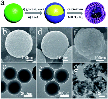
Herein, we demonstrate the design and synthesis of cobalt–nickel oxide/S,N-codoped carbon (referred to as CoNiO2/SNC) with a unique architecture of nanoparticle-constructed microspheres, reminiscent of waxberry. As shown in Fig. 1a, the composite material can be fabricated through a two-step synthesis, where Co–Ni glycerate was used as the precursor while thioacetamide and urea were used as the S and N sources. Such a composite material possesses several features that favor the fast and reliable electrocatalytic OER, ORR and HER processes. First, hierarchical porosity can facilitate the electrolyte penetration during electrochemical test; second, the hollow structure with easily accessible and highly exposed active sites enhances the catalyst–electrolyte contact area and offers sufficient space for electrochemical reactions; third, cobalt–nickel double metal oxide and S,N-codoped carbon composite can be combined to complement each other, and then the synergistic coupling of the two enhances the electrocatalytic activity.27 As such, we believe CoNiO2/SNC hollow nanospheres not only possess improved activity but also excellent stability for OER, ORR and HER.
Experimental section
Materials synthesis
Characterization
The microstructure and morphology of the prepared catalyst was investigated by a Germany Zeiss SUPRA40 field emission scanning electron microscopy (FESEM) at an operating voltage of 15 kV and JEOL-100CX high resolution transmission electron microscopy (HR-TEM) at an operating voltage of 150 kV. XPS measurements were performed on a PHI 5000C ESCA system. The pore structure was analyzed with N2 adsorption–desorption measurements on a Brunauer–Emmett–Teller surface area analyzer (Quantachrome Instruments QuadraSorb SI4) and the pore size distribution was obtained by a Barrett–Joyner–Halenda (BJH) model.Electrochemical measurements
Electrochemical measurements were carried out on a CHI 760E workstation (CH Instruments, Chenhua, Shanghai, China) equipped with a rotating disk electrode in a standard three-electrode cell. A glassy carbon electrode (GC; 5 mm in diameter), a graphite rod, and a saturated calomel electrode (SCE) was used as the working electrode, counter electrode, and the reference electrode, respectively. The potential recorded was converted to the reversible hydrogen electrode (RHE) according to Nernst equation ERHE = ESCE + 0.059 × pH + 0.241. To prepare the sample ink, the electrocatalyst (2.0 mg) was dispersed in isopropanol (485 μL) containing 15 μL 5.0 wt% Nafion solution. The mixture was well dispersed by ultrasonication for 20 min to obtain homogenous ink. Next, 40 μL of ink was loaded onto the pre-polished RDE surface. The ORR, OER and HER tests were performed in O2-saturated 0.1 M KOH solutions, N2-saturated 0.1 M (or 1 M) KOH solutions and N2-saturated 1 M KOH solutions, respectively. For ORR, polarization curves were recorded from 0.1 to −1.0 V (vs. SCE) at a scan rate of 5 mV s−1 with a series of rotating electrode speeds (400, 625, 900, 1225, 1600 and 2025 rpm). The kinetic parameters have been calculated by Koutecky–Levich (K–L) equations28| B = 0.62nFC0(D0)2/3γ−1/6 |
| JK = nFkC0 |
![[thin space (1/6-em)]](https://www.rsc.org/images/entities/char_2009.gif) 485C mol L−1), C0 is the bulk solubility of O2, D0 is diffusion coefficient of O2, γ is the kinematic viscosity of the electrolyte, and k is the electron transfer rate constant. The number of electrons transferred (n) can be obtained from the slope of the K–L plots.
485C mol L−1), C0 is the bulk solubility of O2, D0 is diffusion coefficient of O2, γ is the kinematic viscosity of the electrolyte, and k is the electron transfer rate constant. The number of electrons transferred (n) can be obtained from the slope of the K–L plots.
Linear sweep voltammetry (LSV) for OER and HER were conducted with a scan rate of 5 mV s −1 at room temperature. The iR-compensation was performed by electrochemical impedance spectroscopy to correct the compensated potential. The LSV curves were replotted as potential (V) versus log current (log![[thin space (1/6-em)]](https://www.rsc.org/images/entities/char_2009.gif) j) to get Tafel plots for quantification of the OER and HER kinetic performance of as-prepared catalysts. By fitting the linear part of the Tafel plots to obtain the Tafel slope (b) according to the Tafel equation (V = a + b
j) to get Tafel plots for quantification of the OER and HER kinetic performance of as-prepared catalysts. By fitting the linear part of the Tafel plots to obtain the Tafel slope (b) according to the Tafel equation (V = a + b![[thin space (1/6-em)]](https://www.rsc.org/images/entities/char_2009.gif) log(j)).28 Electrochemical double layer capacitance (Cdl) was calculated by cyclic voltammetry (CV) at nonfaradaic potential range without polarization current. Then the Cdl value has been converted to the electrochemical surface area (ECSA) using the equation ECSA = Cdl/CS (where CS is the specific capacitance with 0.040 mF cm −2 in 1 M KOH electrolyte). Typically, a series of CV curves were recorded at various scan rates (20, 40, 60, 80, 100 mV s−1, etc.) in 0.1 to 0.2 V (vs. SCE) range.
log(j)).28 Electrochemical double layer capacitance (Cdl) was calculated by cyclic voltammetry (CV) at nonfaradaic potential range without polarization current. Then the Cdl value has been converted to the electrochemical surface area (ECSA) using the equation ECSA = Cdl/CS (where CS is the specific capacitance with 0.040 mF cm −2 in 1 M KOH electrolyte). Typically, a series of CV curves were recorded at various scan rates (20, 40, 60, 80, 100 mV s−1, etc.) in 0.1 to 0.2 V (vs. SCE) range.
The stability of catalysts toward ORR, OER, HER was measured by cyclic voltammetry (CV) from 0.0 to −1.0 V (vs. SCE) at a scan rate of 50 mV s−1, 0.0 to 0.7 V (vs. SCE) at a scan rate of 50 mV s−1, −1 to −1.7 V (vs. SCE) at a scan rate of 50 mV s−1, respectively.
Results and discussion
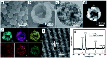
Fig. 1a illustrates the overall synthetic process of waxberry-like hollow CoNiO2/SNC nanocomposites. Firstly, Co–Ni glycerate spheres with an average diameter of 400 nm and a rough surface was obtained by a hydrothermal reaction, as shown in Fig. 1b. The rough surface of Co–Ni glycerate is covered with ultrafine nanoparticles whose diameter is around 10 nm (Fig. S1†). Fig. 1c reveals its solid interior structure. Subsequently, Co–Ni glycerate spheres were treated with glucose, urea, and TAA to achieve carbon coating, nitrogen and sulfur co-doping. Compared with Co–Ni glycerate, the sample after chemical treatment maintains well its spherical morphology and solid interior structure but its surface is smooth (Fig. 1d and e), which can be ascribed to the formation of homogenous and continuous carbon coating on the surface of these microspheres. Lastly, the carbon-coated, N,S-doped, Co–Ni-based microspheres was calcined in flowing N2 atmosphere at 600 °C for 2 h to obtain CoNiO2/SNC nanocomposites (Fig. 1f and g). For comparison, carbon-coated, N-doped, Co–Ni-based nanocomposites, denoted as CoNiOx/NC, were also synthesized by the same procedure except without the TAA-treatment.The representative SEM image of CoNiO2/SNC in Fig. 2a indicates that as-synthesized nanocomposites exhibit a similar spherical morphology but with a smaller diameter of around 300 nm than samples without annealing. The high-magnification SEM image (Fig. 1f) shows that the nanocomposites are constructed by nanoparticles with a size of ca. 60 nm, which looks like waxberry fruit. In stark contrast to samples without annealing, the CoNiOx/SNC also possess a hollow structure (Fig. 2b), which provides not only extra active sites but also faster access to the abundant active sites of the electrocatalysts.26 Such a waxberry-like hollow architecture is further revealed by TEM images (Fig. 2c), which clearly show the nanoparticle-constructed microspheres with a hollow interior, consistent with SEM observations. Fig. 2d shows the high-angle annular dark-field (HAADF) scanning TEM (STEM) image of a single CoNiO2/SNC nanocomposite sphere. The hollow structure is well defined, while the corresponding energy-dispersive X-ray spectroscopy (EDS) mapping result (Fig. 2e) confirms the presence of elements Co, Ni, O, C, N and S with homogeneous dispersion. In particular, the existence of N, S implies the successful N,S doping through the whole CoNiO2/SNC nanocomposites. The high-resolution TEM (HRTEM) image in Fig. 2f shows clear crystal lattice CoNiO2 nanoparticles with an average interplanar spacing of 0.244 nm. The X-ray diffraction (XRD) pattern of the nanocomposites in Fig. 2g can be indexed to a cubic crystal structure (JCPDS No. 10-0188), indicating the formation of highly crystalline CoNiO2, where the (111) plane is well exposed, which is consistent with the HRTEM result. As the control sample, CoNiOx/NC has a similar morphology to CoNiO2/SNC except that the particles of CoNiOx/NC are adhered to each other (Fig. S2†), and XRD (Fig. S3†) also confirms that the control sample is cobalt–nickel oxide nanocomposites.
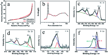
To further understand the porosity of CoNiO2/SNC, N2 adsorption and desorption measurements were conducted. As shown in Fig. 3a, a type-IV isotherm is obtained, suggesting the coexistence of mesopores and macropores.24 The specific surface area of the CoNiO2/SNC nanocomposites is calculated to be 22.1842 m2 g−1 based on the Brunauer–Emmett–Teller (BET) analysis of the nitrogen absorption desorption isotherms. The pore size distribution (Fig. 3b) confirms again the hierarchically porous structure that is probably originated from the assembly of small nanoparticles. X-ray photoelectron spectroscopy (XPS) was used to detect the chemical composition of the CoNiO2/SNC nanocomposites. The survey spectrum (Fig. S4a†) shows the presence of Co, Ni, O, C, N and S elements for the nanocomposites. The high-resolution C 1s spectra was showed in Fig. S4b.†The peaks at 284.5, 286.6 and 288.3 eV correspond to C–C, C–O and C![[double bond, length as m-dash]](https://www.rsc.org/images/entities/char_e001.gif) O bonds, respectively. The binding energy peaks at 284.1 and 285.5 eV are assigned to C–S and C–N, which further indicates the N/S-doping in CoNiO2/SNC hollow nanospheres. As shown in Fig. S4c,† the N 1s existed in the form of pyrrolic N (400.2 eV) and oxidic N (402.3 eV), which would play crucial role in the ORR performances.29 In the Ni 2p region in Fig. 3c, the two peaks at 873.2 and 855.4 eV are attributed to Ni 2p1/2 and 2p3/2 for Ni(II), respectively, along with two shakeup satellites (Sat.). In Fig. 3d, the two peaks centered at 796.4 and 780.7 eV can be assigned to Co 2p1/2 and Co 2p3/2, respectively, and the two weak shoulder peaks at 802.9 and 786.3 eV are the corresponding satellite peaks, confirming the existence of Co(II). As shown in Fig. 3e, the peak at 168.2 eV is attributed to SO42−, arising from the partly oxidized sulfur species (C–SO4).30 Finally, the core-level O 1s spectrum (Fig. 3f) shows three fitting peaks, which are attributed to Ni–O, Co–O and excessive oxygen-containing groups (such as, –OH and C–O) on the sample surface, respectively.31
O bonds, respectively. The binding energy peaks at 284.1 and 285.5 eV are assigned to C–S and C–N, which further indicates the N/S-doping in CoNiO2/SNC hollow nanospheres. As shown in Fig. S4c,† the N 1s existed in the form of pyrrolic N (400.2 eV) and oxidic N (402.3 eV), which would play crucial role in the ORR performances.29 In the Ni 2p region in Fig. 3c, the two peaks at 873.2 and 855.4 eV are attributed to Ni 2p1/2 and 2p3/2 for Ni(II), respectively, along with two shakeup satellites (Sat.). In Fig. 3d, the two peaks centered at 796.4 and 780.7 eV can be assigned to Co 2p1/2 and Co 2p3/2, respectively, and the two weak shoulder peaks at 802.9 and 786.3 eV are the corresponding satellite peaks, confirming the existence of Co(II). As shown in Fig. 3e, the peak at 168.2 eV is attributed to SO42−, arising from the partly oxidized sulfur species (C–SO4).30 Finally, the core-level O 1s spectrum (Fig. 3f) shows three fitting peaks, which are attributed to Ni–O, Co–O and excessive oxygen-containing groups (such as, –OH and C–O) on the sample surface, respectively.31
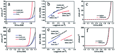
Possessing waxberry-like hollow architecture with hierarchical porosity, S,N-codopant, and strong carbon coupling, CoNiO2/SNC is promising for various electrocatalysis. The electrocatalytic performances of CoNiO2/SNC, CoNiOx/NC and RuO2 towards oxygen evolution reaction (OER) were firstly tested in a three-electrode system with 0.1 M KOH as the electrolyte. The linear sweep voltammetry (LSV) curves illustrate that CoNiO2/SNC requires the overpotentials of only around 381 mV to deliver the current densities of 10 mA cm−2 (Fig. 4a), which is much lower than those of CoNiOx/NC (429 mV) and RuO2 (490 mV). Fig. 4b manifests that the Tafel slope for CoNiO2/SNC is 34 mV dec−1, smaller than that of CoNiOx/NC (64 mV dec−1) and RuO2 (109 mV dec−1), indicating the faster OER kinetics of CoNiO2/SNC. It is worth mentioning that CoNiO2/SNC shows superior activity to the precious metal-based catalysts (RuO2), implying its high applicability. In addition, the OER performance of the three samples were tested in 1 M KOH. Although the same activity trend of three catalysts, a better catalytic activity was obtained in 1 M KOH. The overpotential and Tafel slope for CoNiO2/SNC, CoNiOx/NC and RuO2 are 280 mV, 335 mV, 329 mV, 55 mV dec−1, and 58 mV dec−1, 72 mV dec−1, respectively (Fig. 4d and e). Such an exceptional OER activity of CoNiO2/SNC is comparable and even superior to recently reported OER catalysts (Table S1†). Besides, cyclic voltammetry (CV) measurements at different sweep speed were performed to investigate the electrochemically active surface area (ECSA) of the sample. In the potential range from 1.1 to 1.2 V, there is not faradaic current observed (Fig. S5a and b†). According to the linear relationship between current density and scan rates (Fig. S5c†), the Cdl values of the CoNiO2/SNC and CoNiOx/NC are calculated to be 68.78 and 40.25 mF, respectively. Therefore, it is concluded that the ECSA of CoNiO2/SNC is much larger than CoNiOx/NC. It shows that there are more active sites exposed in CoNiO2/SNC, which greatly improves the performance of OER. Subsequently, durability of CoNiO2/SNC for water oxidation in both 0.1 M and 1 M KOH were measured by cyclic voltammetry (CV). As shown in Fig. 4c and f, CoNiO2/SNC manifests only negligible current loss even after 1000 cycles.
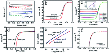
Next, the electrocatalytic ORR performance of the CoNiO2/SNC catalyst was studied. Cyclic voltammetry (CV) measurements were initially carried out in a conventional three-electrode electrochemical cell in an O2- or N2-saturated 0.1 M KOH solution. In the absence of oxygen, no redox peaks were observed for CoNiO2/SNC and CoNiOx/NC (Fig. 5a). By contrast, apparent cathodic peaks at 0.59 V (versus reversible hydrogen electrode, RHE) were detected in O2-saturated solution, indicating the electrocatalytic activity of CoNiO2/SNC and CoNiOx/NC. Moreover, the peak current density of CoNiO2/SNC is higher than CoNiOx/NC, suggestive of a better electrocatalytic activity of CoNiO2/SNC. To further evaluate the ORR performance of the CoNiO2/SNC, rotating disk electrode tests were performed in O2-saturated 0.1 M KOH at a rotation rate of 1600 rpm. Fig. 5b shows that the waxberry-like hollow CoNiO2/SNC nanocomposites exhibit more positive onset and half-wave potentials (0.85 and 0.70 V, respectively) than those of the CoNiOx/NC (0.845 and 0.67 V, respectively). Also, the diffusion-limiting current density of CoNiOx/SNC is 6.5 mA cm−2, which is higher than that of CoNiOx/NC (5.4 mA cm−2), confirming the superior activity of CoNiO2/SNC to CoNiO2/NC. Of note, the high catalytic activity of CoNiO2/SNC is comparable and even superior to recently reported non-precious metal ORR catalysts, such as Fe2N-NGC1-1000 (0.83 and 0.66 V vs. RHE)31, NiCo2O4-rGO (0.85 and 0.58 V vs. RHE)32 and hollowed-out MnCo2O4.5 nanocages (0.8 and 0.7 V vs. RHE).33 To investigate the ORR kinetics of the CoNiO2/SNC electrocatalyst, polarization curves were obtained at various rotation speeds ranging from 400 to 2025 rpm with a scan rate of 5 mV s −1. As shown in Fig. 5c, the CoNiO2/SNC exhibited a well-defined platform of diffusion-limiting currents at all rotational speeds. Derived from Fig. 5c, K–L plots were obtained (Fig. 5c inset), showing good linearity at various potentials in the mass-transport-limited region (0.2–0.5 V vs. RHE, Fig. 5c), suggesting the first-order reaction kinetics with respect to oxygen. According to the calculation, the number of electron transfer is close to 4 (Fig. S6†), indicating a four electron transfer process from the reduction of O2 to the formation of H2O. Subsequently, the stability of CoNiO2/SNC catalyst in 0.1 M KOH was measured by cyclic voltammetry (CV). The CoNiO2/SNC catalyst exhibits excellent stability towards the ORR without significant losses in activity after 6000 cycles (Fig. S7†). Apart from the bifunctional catalysis toward ORR and OER, the CoNiO2/SNC catalyst also displays good performance for HER. According to the polarization curves (Fig. 5d), a decent HER catalytic activity can be achieved for the CoNiO2/SNC catalyst which has an onset potential of about 0.23 V as well as a overpotential of around 330 mV at the current density of 10 mA cm−2. Derived from polarization curves, Tafel curves (Fig. 5e) showcase the Tafel value of CoNiO2/SNC is 101 mV dec−1, implying HER behavior proceeds via a Volmer–Tafel mechanism with electrochemical desorption of hydrogen as the rate-limiting step. These values (onset potential, overpotential and Tafel slope) of CoNiO2/SNC are much lower than those of control sample, again substantiating the superior catalytic activity of CoNiO2/SNC. Fig. 5f show the stability test for HER. CoNiO2/SNC manifests only negligible current loss even after 1000 cycles. The above results show that CoNiO2/SNC nanocomposites catalyst possesses excellent trifunctional electrocatalytic activity towards the ORR, OER and HER.
After the stability test, hollow waxberry-like CoNiO2/SNC nanocomposites were again characterized by SEM and TEM. The results are shown in Fig. S8.† The SEM and TEM images show that the morphology and structure of the sample did not change significantly after the stability test. The results show that this hollow waxberry-like CoNiO2/SNC nanocomposites have excellent stability.
Conclusions
In summary, we have successfully developed, for the first time, CoNiO2/SNC nanocomposites with the unique waxberry-like hollow architecture as trifunctional electrocatalysts towards OER, ORR, and HER. Benefiting from its unique hierarchical porosity, hollow structure and the strongly coupling of CoNiO2 and N,S-codoped carbon, the CoNiO2/SNC electrocatalyst manifests excellent activity and good stability for OER, ORR, and HER in alkaline media. Furthermore, our approach may be further applied to other transition metal oxide, sulfides, phosphides, and nitrides with carbon coating and heteroatom-doping, thus opening a new avenue for constructing multifunctional electrocatalysts and electrodes in fuel cells, metal–air battery, and water splitting.Conflicts of interest
There is no conflict of interest to declare.Acknowledgements
This work was financially supported by the National Natural Science Foundation of China (Grant No. 51922008 and 51872075), the 111 Project (Grant No. D17007), Henan Center for Outstanding Overseas Scientists (Grant No. GZS2018003).Notes and references
- D. U. Lee, P. Xu, Z. P. Cano, A. G. Kashkooli, M. G. Park and Z. Chen, J. Mater. Chem. A, 2016, 4(19), 7107–7134 RSC.
- Z. Bai, S. Li, J. Fu, Q. Zhang, F. Chang, L. Yang, J. Lu and Z. Chen, Nano Energy, 2019, 58, 680–686 CrossRef CAS.
- V. Bernales, M. A. Ortuno, D. G. Truhlar, C. J. Cramer and L. Gagliardi, ACS Cent. Sci., 2018, 4(1), 5–19 CrossRef CAS PubMed.
- L. Xue, Y. Li, X. Liu, Q. Liu, J. Shang, H. Duan, L. Dai and J. Shui, Nat. Commun., 2018, 9(1), 3819 CrossRef PubMed.
- F. Meng, H. Zhong, D. Bao, J. Yan and X. Zhang, J. Am. Chem. Soc., 2016, 138(32), 10226–10231 CrossRef CAS PubMed.
- M. Jahan, Z. Liu and K. P. Loh, Adv. Funct. Mater., 2013, 23(43), 5363–5372 CrossRef CAS.
- J. Yang, X. Wang, B. Li, L. Ma, L. Shi, Y. Xiong and H. Xu, Adv. Funct. Mater., 2017, 27(17), 1606497 CrossRef.
- J. Yin, Y. Li, F. Lv, M. Lu, K. Su, W. Wang, L. Wang, F. Cheng, Y. Li, P. Xi and S. Guo, Adv. Mater., 2017, 29(47), 1704681 CrossRef PubMed.
- F. Cheng and J. Chen, Chem. Soc. Rev., 2012, 41(6), 2172–2192 RSC.
- Y. Jiao, Y. Zheng, M. Jaroniec and S. Z. Qiao, Chem. Soc. Rev., 2015, 44(8), 2060–2086 RSC.
- T. Yu, D. Y. Kim, H. Zhang and Y. Xia, Angew. Chem., Int. Ed. Engl., 2011, 50(12), 2773–2777 CrossRef CAS PubMed.
- Z. Peng and H. Yang, J. Am. Chem. Soc., 2009, 131, 7542–7543 CrossRef CAS PubMed.
- Y. Lee, J. Suntivich, K. J. May, E. E. Perry and Y. Shao-Horn, J. Phys. Chem. Lett., 2012, 3(3), 399–404 CrossRef CAS PubMed.
- B. Chen, X. He, F. Yin, H. Wang, D. Liu, R. Shi, J. Chen and H. Yin, Adv. Funct. Mater., 2017, 27(37), 1700795 CrossRef.
- Y. Gorlin and T. F. Jaramillo, J. Am. Chem. Soc., 2010, 132, 13612–13614 CrossRef CAS PubMed.
- Y. Gong, Z. Xu, H. Pan, Y. Lin, Z. Yang and X. Du, J. Mater. Chem. A, 2018, 6(12), 5098–5106 RSC.
- J. Zhang and L. Dai, Angew. Chem., Int. Ed., 2016, 55(42), 13296–13300 CrossRef CAS PubMed.
- B. Y. Guan, L. Yu and X. W. D. Lou, Adv. Sci., 2017, 4(10), 1700247 CrossRef PubMed.
- H. Shen, E. Gracia-Espino and J. Ma, Angew. Chem., Int. Ed. Engl., 2017, 56(44), 13800–13804 CrossRef CAS PubMed.
- L. Yu, J. F. Yang, B. Y. Guan, Y. Lu and X. W. D. Lou, Angew. Chem., Int. Ed. Engl., 2018, 57(1), 172–176 CrossRef CAS PubMed.
- W. Gao, J. Qin, K. Wang, K. Yan, Z. Liu, J. Lin and B. Dong, Appl. Surf. Sci., 2018, 454, 46–53 CrossRef CAS.
- F. Wang, Y. Sun, Y. He, L. Liu, J. Xu, X. Zhao, G. Yin, L. Zhang, S. Li, Q. Mao, Y. Huang, T. Zhang and B. Liu, Nano Energy, 2017, 37, 1–6 CrossRef CAS.
- F. Wang, X. Yang, B. Dong, X. Yu, H. Xue and L. Feng, Electrochem. Commun., 2018, 92, 33–38 CrossRef CAS.
- G. Li, X. Wang, J. Fu, J. Li, Y. Zhang, M. G. Park and Z. Chen, Angew. Chem., Int. Ed., 2016, 55(16), 4977–4982 CrossRef CAS PubMed.
- J. Zhang and L. Dai, Angew. Chem., Int. Ed., 2016, 55, 13296–13300 CrossRef CAS PubMed.
- D. U. Lee, H. W. Park, M. G. Park, V. Ismayilov and Z. Chen, ACS Appl. Mater. Interfaces, 2015, 7(1), 902–910 CrossRef CAS PubMed.
- F. Kong, X. Fan, A. Kong, Z. Zhou, X. Zhang and Y. Shan, Adv. Funct. Mater., 2018, 28(51), 1803973 CrossRef.
- K. Zhang, C. Qu and Z. Liang, ACS Appl. Mater. Interfaces, 2018, 10(36), 30460–30469 CrossRef CAS PubMed.
- W. Fang, H. Hu, T. Jiang, G. Li and M. Wu, Carbon, 2019, 146, 476–485 CrossRef CAS.
- Z. Hong, Y. Zhen, Y. Ruan, M. Kang, K. Zhou, J. Zhang, Z. Huang and M. Wei, Adv. Mater., 2018, 1802035 CrossRef PubMed.
- Z. Wang, J. Yin, Z. Zhao, Y. Zhang, G. Pang, X. Sun, J. Zhang and C. Yuan, J. Alloys Compd., 2019, 779, 81–90 CrossRef CAS.
- G. Zhang, B. Y. Xia, X. Wang and X. W. David Lou, Adv. Mater., 2014, 26(15), 2408–2412 CrossRef CAS PubMed.
- Z. Bai, J. Heng, Q. Zhang, L. Yang and F. Chang, Adv. Energy Mater., 2018, 1802390 CrossRef.
Footnote |
| † Electronic supplementary information (ESI) available. See DOI: 10.1039/d0ra03222k |
| This journal is © The Royal Society of Chemistry 2020 |

