 Open Access Article
Experimental investigation on the effects of multiple injections and EGR on n-pentanol–biodiesel fuelled RCCI engine
Sabu V. R. *,
Justin Jacob Thomas
 and
Nagarajan G.
ICE Division, Anna University, Chennai, India. E-mail: sabuvr@gmail.com; Tel: +91 9447388555
First published on 10th August 2020
Abstract
Stringent emissions and fuel economy regulations have necessitated the need to boost the research interest in oxygenated alternate fuels such as n-pentanol and biodiesel under low-temperature combustion strategies due to their renewability and cleaner combustion characteristics. Being higher alcohol, n-pentanol has desirable fuel properties that are comparable to mineral diesel, which enable easy blending of these fuels. In the present study, the Reactivity Controlled Compression Ignition (RCCI) operation in a modified single-cylinder diesel engine operating at the rated speed of 1500 rpm and 50% load was investigated with non-edible karanja oil-based biodiesel–diesel blend with B20 as high reactivity fuel (HRF) and n-pentanol as low reactivity fuel (LRF). The intake temperature was maintained constant at 40 °C, intake pressure was ambient and the LRF was varied from 20% to 50%. The engine's performance with split injection was investigated by sweeping starts of injection (SOI) crank angles and these were optimized at 47°, 27°, and 17° bTDC for SOI 1, SOI 2, and SOI 3 respectively at 400 bar injection pressure. The engine performance characteristics were investigated by introducing 10% to 30% cooled exhaust gas recirculation (EGR) and was optimized at 25%, based on the stable operation of the engine with acceptable ringing intensity and emission. The combined effect of EGR, multiple injections (three), and varying PFI mass fractions was investigated and compared with a single injection of HRF. A simultaneous reduction of 76% smoke and 91.5% NOX emission was obtained with a marginal increase in CO and HC emissions.
1 Introduction
The transportation sector makes up a significant share of global energy utilization and greenhouse gas emissions.1 Hence achieving high energy efficiency by meeting the stringent emission mandate is the heart of any strategy to guarantee secure, sustainable, and inclusive economic growth.2 The progressive inventions in the internal combustion (IC) engines can be broadly categorized into fuel reformation, engine technologies, and post-combustion treatments. The introduction of electronic engine management systems has significantly improved fuel efficiency and reduced pollutant emission from automotive engines. Though the compression ignition (CI) engines have higher thermal efficiency and fuel efficiency than spark ignition (SI) engines, under conventional diesel operation, the regions of the combustion chamber are often subjected to rich and high-temperature lean charge, leading to the formation of soot and NOX respectively. The major challenge faced by the CI engines is the trade-off between NOX and soot. The recent research in IC engine combustion is focused on low-temperature combustion (LTC),3 a generic term used for advanced combustion strategies with the ultimate goal of lowering the combustion temperature to maximize engine efficiency and to minimize the exhaust emissions. Most of the current combustion strategies on the in-cylinder reduction of NOX and soot can be lumped into the area of premixed LTC, targeted to by-pass NOX and soot formation zones by maintaining low temperature either by the use of cold EGR or by operating with excess air ratio higher than 1.4 Lower combustion temperatures less than 2000 K reduce the formation of NOX as NO formation reactions require high activation energy. Many researchers have successfully demonstrated the concepts of premixed charge compression ignition (PCCI) and homogeneous charge compression ignition (HCCI) for the simultaneous reduction of NOX and Soot5,6. All the LTC strategies allow a longer ignition delay period or a positive ignition dwell (time lag between the end of fuel injection and the start of combustion). Researchers have demonstrated the methods to reduce the excessive CO and UBHC emissions from HCCI and PCCI through improved piston designs with reduced crevice volume and by forced induction7,8. RCCI is one such LTC strategies, wherein, two fuels of different reactivities are used.9 The diesel-like fuels or fuels with lower self-ignition temperature (SIT) are referred to as high reactivity fuel and gasoline-like fuels or fuels with higher SIT are referred to as low reactivity fuel. The fuel reactivity can be categorized into two; global reactivity and reactivity gradient. The global reactivity is determined by the fuel type and its amount injected into the cylinder. The reactivity gradient depends upon the fuel spray penetration and the entrainment of direct-injected fuel with injection strategies like early, late injection or multiple injections.10To control the fuel reactivity, RCCI combustion uses the technique of in-cylinder blending of two fuels with different auto-ignition characteristics, injected at planned intervals for obtaining the desired combustion phasing4,11. The progressive combustion in RCCI reduces the high rate of pressure rise and ringing intensity, which help in achieving a wider range of engine operations. The absence of high-temperature regions near the piston bowl in RCCI combustion reduces the heat transfer losses and results in higher thermal efficiency as compared to CDC.4 To achieve higher thermal efficiency and reduce NOX and particulate emissions, RCCI also uses multiple injection in one cycle along with EGR. The RCCI mode of operation can meet the PM and NOX regulation limits without using after-treatment devices. Though it offers many encouraging features as cited above, the major limitations include higher UBHC and CO emissions.12 The conventional approaches to curb the engine exhaust emissions include modified in-cylinder engine technologies and after-treatment methods. But, one of the major limitations in RCCI using the after-treatment methods is that it reduces the conversion efficiency of the catalytic converters due to the lower exhaust temperature.13 Since the LTC strategies are influenced and controlled by the fuel chemical kinetics, fuel molecular structure and properties play an important role in influencing ignition timing control, engine operational limits and emission formation4,14. Hence it is expected that the use of alternative fuels in RCCI, especially oxygenated biofuels with comparable reactivity gradients, would help to address major limitations associated with excessive CO and unburned hydrocarbon (UBHC) emissions.
Researchers have used a wide range of renewable and oxygenated alternate fuels including alcohol and biofuels in RCCI combustion to achieve the reactivity gradient between the primary and the secondary fuel. In SI engines, gasoline–alcohol blends are very often used15,16, whereas, in CI engines, alcohols are used as micro-emulsions, by fumigation, pilot injection or direct diesel–alcohol blending.17 The utilization of long-chain alcohols such as n-pentanol has received remarkable attention as an alternate fuel for diesel engines in recent times.18 Limited literature is available on the effect of neat n-pentanol on the performance, combustion, and emission characteristics in CI engines. It was reported by Lapuerta et al., (2010)19 that longer-chain alcohols are more desirable than short-chain alcohols because of their superior lubricity, energy density, viscosity, and low hygroscopicity. Production of longer-chain alcohol from nonedible feedstocks makes them a promising transportation fuel. An experiment conducted on single-cylinder diesel engine with n-pentanol/diesel/biodiesel blends without EGR20 showed reduced NOX and soot emissions compared to diesel. Wei et al., (2014)21 reported that the addition of n-pentanol in n-pentanol/diesel blends increased brake specific fuel consumption (BSFC) due to their low calorific value. The brake thermal efficiency (BTE) remained unaffected with an increase in n-pentanol percentage in the blends. Experimental results for n-pentanol/diesel blends showed that the addition of n-pentanol led to longer ignition delay, increased peak heat release rate, and rapid rise in the cylinder pressure in the premixed combustion phase. Besides, n-pentanol addition results in the increase of CO and UBHC emission at low engine load, whereas the emission decreases at higher engine load.22 Simultaneous reduction of smoke and NOX was reported23,24 by using the combination of n-pentanol/diesel blends, late injection by 2 CAD, and moderate EGR of 30%. Pan et al., (2019)25 employed visualization and engine experimental test methods to study the spray, combustion, and emission performance of diesel/n-pentanol mixtures and reported that the method has considerably reduced the NOX emission and the atomization characteristics of diesel/n-pentanol mixtures were better than that of diesel.
Biodiesel or fatty acid methyl ester (FAME), defined as the mono-alkyl esters of vegetable oils or animal fats is an environmentally attractive alternative fuel to mineral diesel. The B20 blend (biodiesel 20% and 80% diesel) is the most commonly accepted blend because it helps earlier start of combustion, shorter ignition delay, longer combustion duration, lower heat release rate (both premixed and total) and less engine wear as compared to CDC.26,27 Researchers have emphasized that non-edible karanja (Pongamia pinnata) oil-based biodiesel is a promising alternative fuel,28 which could be blended with mineral diesel for direct displacement29,30. The commercial biodiesel extraction from karanja has proved to be economic because it is non-edible and can be planted even in wastelands. In a few studies, researchers have also used biodiesel for RCCI engines as the high reactive fuel owing to its higher cetane number compared to mineral diesel4,31. Another reason for the preferred application of biodiesel for RCCI experiments is the presence of oxygen in it, which promotes soot oxidation, leading to a further reduction of particulate emissions.32
Two efficient methods for using EGR are residual gas trapping through negative valve timing and external rebreathing. Higher fractions of cold EGR are used to achieve longer ignition delay and NOX reduction by effectively mixing and lowering the in-cylinder combustion temperature. The heat capacity effect of the charge reduces the temperature and hence this will result in reduced NOX formation. Jain et al., (2017) demonstrated the use of EGR for charge stratification to control the rapid heat release and lowering combustion noise in the LTC engine. The effect of split injection and EGR was investigated on a four-cylinder CRDI engine33 and the results showed improved combustion and lower emissions. However, a higher rate of EGR resulted in inferior engine performance due to a reduction in bulk cylinder temperature. The performance analysis of a light-duty CRDI engine on split injection and cooled EGR34 revealed that the split injection reduced the combustion duration, ignition delay, and exhaust gas temperature for higher EGR flow rates compared to single injection. The influence of split injection mass and injection pressure on a methanol/diesel RCCI engine was investigated35 and it was reported that a 60% mass fraction of pilot fuel resulted in less NOX emission.
In the present work, an experimental investigation was conducted on a modified single-cylinder light-duty water-cooled diesel engine to investigate the influence of multiple injections and different percentage of EGR on karanja B20/neat n-pentanol RCCI operation by introducing n-pentanol as port injected fuel and karanja B20 as directly injected fuel through three split injections on the engine performance. In the present study, n-pentanol was injected at 3 bar pressure into the intake port and karanja B20 was injected directly at 400 bar pressure at 50% load. The fuel split mass and the amount of EGR greatly affects fuel reactivity gradients. The engine performance characteristics were also investigated by introducing 10% to 30% cooled exhaust gas recirculation (EGR). The EGR quantity was optimized based on the stable operation of the engine with acceptable ringing intensity and emission.
2 Experimental test setup and methodology
2.1 Experimental engine modifications
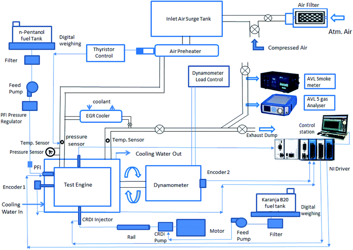
A commercially available (Kirloskar AV 1) single-cylinder, 3.7 kW, vertical, water-cooled, 4 stroke CI engine was befittingly modified with electronic engine management and combustion analyzing systems to achieve dual-fuel RCCI at rated speed and varying loads at 400 bar injection pressure. The engine was coupled with an eddy current dynamometer to provide an electrical loading facility. A closed-loop thyristor controlled air pre-heater with 1500 W heating coil capacity was fabricated and installed next to the air surge tank to enable constant intake air temperature. The K-type thermocouples installed in the intake, exhaust, cooling water jacket were connected to the temperature control unit to constantly monitor the operating temperatures. The exhaust manifold was connected to an EGR cooler with control valves to induct hot or cooled exhaust gases as per the operational requirements. A vacuum pump driven by an electrical motor and an electronic modulator was used to control the percentage of EGR. The EGR rate was calculated23,36 under steady operating conditions by the ratio of intake CO2 to exhaust CO2 levels measured by the AVL exhaust gas analyzer using the following relation.
 | (1) |
The engine cylinder head was modified to mount the port fuel injector with an adaptor. The conventional mechanical injector was replaced with a Delphi six-hole solenoid-operated injector through a specially designed attachment. A Kistler make piezoelectric pressure transducer placed adjacent to the fuel injector was used for sensing the in-cylinder pressure. The mechanical fuel injection system was modified by incorporating a high-pressure CRDI system driven by National Instruments Direct Injection Driver System (DIDS) with proportional-integral-derivative (PID) control to take care of the fuel governing. The rotary encoders to pick up the cam and crank positions were fixed by suitably attaching an extension to the engine crankshaft and the dynamometer shaft. The mass flow rate of the test fuels introduced into the engine was measured using a gravimetric digital balance and the time taken for the consumption of 20 grams of the test fuels was noted down using a digital stopwatch. The schematic of the experimental setup is shown in Fig. 1. The details of the test engine are furnished in Table 1. The fuel injection system specifications are given in Table 2.
| Description | Values |
|---|---|
| Engine type: (Kirloskar AV 1) – single cylinder, vertical, water-cooled, 4S, compression ignition | |
| Bore × stroke (mm) | 80 × 110 |
| Displacement (cm3) | 553 |
| Compression ratio | 16.5![[thin space (1/6-em)]](https://www.rsc.org/images/entities/char_2009.gif) : :![[thin space (1/6-em)]](https://www.rsc.org/images/entities/char_2009.gif) 1 1 |
| Rated output (kW) | 3.7 |
| Rated speed (rpm) | 1500 |
| Torque at full load (kN m) | 0.024 |
| Injection system | CRDI & PFI (modified) |
| Injection pressure | CRDI 400 bar, PFI-3 bar |
| Injection timings | SOI1 – 47° bTDC, SOI 2 – 27° bTDC, SOI 3 – 17° bTDC |
| Inlet valve opening | 5° bTDC |
| Inlet valve closing | 35° aBDC |
| Exhaust valve opening | 355° bBDC |
| Exhaust valve closing | 5° aTDC |
| Description | Specifications |
|---|---|
| Port injection system | |
| PFI fuel (low reactivity) | Neat n-pentanol |
| PFI injector (solenoid type) | Denso, 4 holes, 56–58 ml/15 s, 11.6–12.4 Ω resistance at 20 °C, 12 V |
| Fuel injection pressure | 3 bar (regulated) |
| Injection strategy | Single, 355° bTDC |
| Port fuel injection driver module | NI 9758 |
![[thin space (1/6-em)]](https://www.rsc.org/images/entities/char_2009.gif) |
|
| CRDI injection system | |
| Direct injection fuel (high reactivity) | Karanja biodiesel B20 |
| High-pressure pump | Bosch CP1, plunger dia 7 mm |
| High-pressure rail | Bosch, rail capacity −19 cm3 |
| Fuel injection pressure | 400 bar (regulated) |
| CRDI injector (solenoid type) | Delphi, 6 holes, 12 V |
| Injection strategy | Multiple (three) |
| SOI 1 sweep from 41° to 49° | |
| SOI 2 sweep from 21° to 29° and SOI 3 sweep from 11° to 19° bTDC | |
| CRDI fuel injection driver module | NI 9751 |
| CRDI fuel control method | PID |
2.2 Low-pressure PFI system
The engine cylinder head was modified to accommodate a Denso make, solenoid type, four-hole fuel injector for injecting the low reactivity fuel n-pentanol into the port. Since the fuel feed pump pressure was high, multi-stage pressure reduction was done through a set of control valves to bring down the injection pressure to the required 3 bar. The National Instruments PFI driver module NI 9758 uses the input signal from the encoder for effectively controlling the injection timing and injector pulse width adjustments for injection quantity as per the fixed energy share of the fuel for various experimental conditions. A single injection at 355° bTDC was used during the experiment. The mass fraction of the PFI fuel n-pentanol was calculated37 based on the energy share of the test fuels by considering their calorific value.2.3 High-pressure direct-injection system
The National Instruments DIDS was used for the electronic control of dual-fuel RCCI operation. The ECU requires the cam position sensor pulse at compression TDC since the injection timings in the software take compression TDC as reference.A Kistler encoder with 0.1° CA precision was used for crank position sensing. The Bosch common rail acts as an accumulator to pressurize the fuel at the operating pressure of 400 bar.
The piezo-resistive type of rail pressure sensor gives the signal of instantaneous rail pressure as a voltage signal to the ECU and the ECU adjusts the pressure relief valve in the rail to maintain the required operating pressure. The Bosch CP1 model CRDI pump was driven by a 3.7 kW 3-phase motor to build up sufficient rail pressure. A separate copper cooling coil facility was provided to cool the hot fuel coming through the return line of the injector back to the tank. The compression ratio of 16.5 and the original equipment manufacturers (OEM) piston with a hemispherical bowl was retained during the experiments. The engine was warmed up and allowed to reach a steady-state before recording the experimental readings. All sets of experimental data were repeated thrice and average values were taken. Most of the constant speed non-road light-duty diesel engines are often subjected to medium load operating conditions. Hence, the results are presented for 50% load only.
2.4 Test procedure
The modified diesel engine with PFI and CRDI capability to operate in RCCI mode was initially run at the rated speed of 1500 rpm with diesel fuel at all range of loads and later switched over to karanja biodiesel blend B20. The dual-fuel RCCI operation was successfully performed at all ranges of loads using n-pentanol fuel as the low reactivity PFI fuel and B20 as the high reactivity direct injection fuel at the rated speed. The influence of operating parameters like injection timing, multiple injections, and the percentage of LRF substitution and EGR fraction were examined and optimized. The intake pressure was atmospheric and the intake temperature was maintained at 40 °C throughout the study. The fuel split mass and the amount of EGR greatly affects the fuel reactivity gradients. The experiments were conducted by varying the EGR fraction from 10% to 30%. The engine performance with split injection was examined by sweeping SOI 1 from 41° to 49°, SOI 2 sweep from 21° to 29° and SOI 3 from 11° to 19° bTDC.The details of the measuring instruments are shown in Table 3, test fuel properties are shown in Table 4 and the engine operating conditions are furnished in Table 5.
| Exhaust gas analyser (AVL di gas 444) | ||
|---|---|---|
| Equipment | Range | Accuracy |
| Oxygen | 22% vol | <2% vol: ±0.1% vol |
| >2% vol: ±5% vol | ||
| Carbon monoxide | 10% vol | <0.6% vol: ±0.03% vol |
| >0.6% vol: ±5% vol | ||
| Carbon dioxide | 20% vol | <10% vol: ±0.5% vol |
| >10% vol: ±5% vol | ||
| Hydro carbon | 20![[thin space (1/6-em)]](https://www.rsc.org/images/entities/char_2009.gif) 000 ppm 000 ppm |
<200 ppm: ±10 ppm |
| >200 ppm: ±5% of value | ||
| Nitrogen oxide | 5000 ppm | <500 ppm: ±50 ppm |
| Smoke meter-(AVL 437C) | 0–100% opacity | ±1% full scale |
| Cylinder pressure sensor (Kistler: 6052 C32) | 0–250 bar | ±1 bar |
| Digital mass weighbridge | 0–10 kg | ±0.2 g |
| Thermocouple grade – K type | −200 to 1350 °C | ±2.2 °C or ±0.75% |
| Fuel properties | Range | Pentanol | Karanja B20 |
|---|---|---|---|
| Lower heating value | MJ kg−1 | 31 | 43.49 |
| Cetane number | 20 | 51 | |
| Viscosity at 400 °C | mm2 s−1 | 1.75 | 2.72 |
| Density at 200 °C | kg m−3 | 804 | 435 |
| Latent heat of vaporization | kJ kg−1 | 728 | 270–375 |
| Vapor pressure at 380 °C | kPa | 20 | 0.4 |
| Parameters | Details |
|---|---|
| Engine speed | 1500 rpm |
| Load | 50% load |
| Mode of operation | RCCI |
| PFI timing | 355° bTDC |
| PFI pressure | 3 bar |
| DI injection (CRDI) timing | Split, 3 injections |
| DI injection pressure | 400 bar |
| Air intake | Natural aspiration |
| Air intake temperature | 40 °C, constant |
| EGR intake | 25% |
3 Results and discussion
3.1 Effect of cooled EGR on combustion and emission characteristics
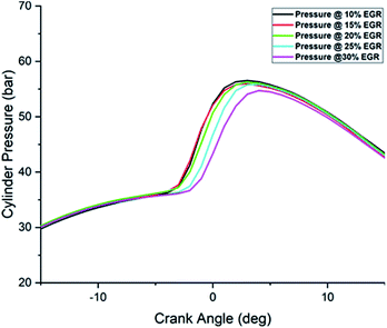
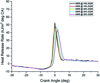
The presence of recycled or trapped residual gases inside the combustion chamber is expected to influence the combustion and emission characteristics in RCCI engine. Primarily the introduction of the burnt gases in the cylinder replaces the fraction of oxygen in the charge and creates a dilution effect. The total heat capacity of the in-cylinder charge will be higher with residual gases, mainly owing to the higher heat capacity values of CO2 and water vapor. The presence of intermediate species of combustion can influence the chemical kinetics of combustion resulting in altering its auto-ignition characteristics. The cylinder pressure vs. crank angle for the RCCI combustion at 50% load with EGR fraction varying from 10% to 30% at 400 bar pressure is shown in Fig. 2. As the fraction of EGR in the charge is increased, due to the replacement of fresh oxygen with EGR, the dilution effect retards as well as lowers the combustion temperature and pressure. RCCI combustion is influenced by chemical kinetics, temperature, and fuel stratification and has retarded the start of combustion. The cylinder pressure is reduced by 2% and 4% with 25% and 30% EGR respectively compared to 10% EGR.Fig. 3 shows the traces of the heat release rate and it is observed to be decreasing proportionally with an increase in EGR percentage from 10% to 30%. The dilution of the oxidizer components and the lowered combustion temperature due to delayed combustion has influenced the reduction in the heat release rate. It can also be noted that the slope of the HRR curve (rate of HRR) reduces with an increase in EGR.
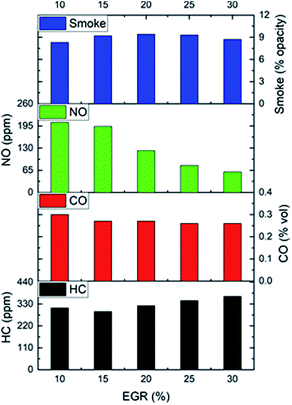
Simultaneous reduction of thermal NOX and soot from the diesel engine is a challenge. The use of EGR is an effective strategy to control the NOX emission in the exhaust. The EGR fraction in the charge will increase the heat capacity of the working fluid and will reduce the flame temperature. Moreover, the endothermic dissociation reactions of the EGR components such as water vapor will also influence in reducing the flame temperature. The exhaust emission characteristics of the test engine with karanja biodiesel B20–n-pentanol RCCI combustion are depicted in Fig. 4. The reduction in NOX emission is observed with increasing percentage of EGR mainly owing to the reduction in combustion temperature, oxygen, and an increase in heat capacity. The smoke opacity shows increasing trend with increased EGR percentage because of the absence of sufficient oxygen and reduced combustion temperature. The CO emission is an indication of incomplete combustion. A marginal change in the CO emissions with the change in EGR percentage is observed. The HC emission shows an increasing trend with increase in EGR percentage. The higher latent heat of evaporation of n-pentanol induces a cooling effect that results in decreased oxidation rate and increased HC emissions. This can be further substantiated with poor combustion due to insufficient availability of oxygen. Considering the peak cylinder pressure, heat release rate, and the emission characteristics of NOX and smoke opacity, the optimum EGR at 400 bar pressure and 50% load is observed to be 25%.
3.2 Effect of multiple injections on combustion and emission characteristics
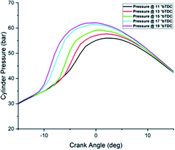
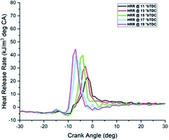
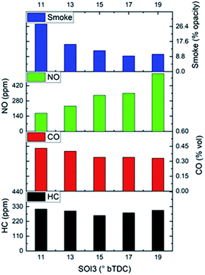
The fuel injection strategy plays an important role in RCCI combustion for achieving the desired combustion phasing. There are many controllable parameters in electronic fuel injection like injection timing, split injections, SOI timings of each injection, and the time lag between them, varying the pulse width and duty cycle of the injector. The SOI timing of HRF is one of the most important parameters that allow fuel reactivity, equivalence ratio, and temperature stratification inside the cylinder. In the present study, the engine performance with three split injections was examined by sweeping in the order SOI 3 from 11° to 19°, SOI 2 from 21° to 29° and SOI 1 from 41° to 49° bTDC. While studying the effect of a particular injection angle, other two injection angles were kept constant. The ambient temperature was maintained constant at 40 °C, without EGR, the injection pressure was 400 bar and HRF mass was split to 30%, 30%, and 40% for SOI 1, SOI 2 & SOI 3 respectively.The impact of SOI 3 change on emission characteristics of the engine is shown in Fig. 7. It can be observed that by advancing the SOI 3 timing, the smoke level shows a decreasing trend. The early injections allow better mixing and homogeneous mixture preparation due to the availability of more time. Advancing the SOI 3 has shown an increase in the NOX emission. Due to the increased ignition delay and accumulation of more fuel before combustion, heat release rate and in-cylinder temperature increase favoring the formation of more NOX. By advancing the SOI 3 timing, CO emission shows a decreasing trend due to increased cylinder temperature and CO to CO2 conversion. Only a marginal reduction in the HC emission is observed with advancing SOI 3 timings. Hence the acceptable SOI 3 angle is observed to be 17° bTDC.
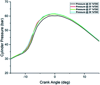
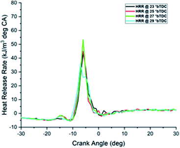
The cylinder pressure and heat release rate trends observed are almost similar to SOI 3 sweep. There is not much deviation in the peak cylinder pressure. Advancing the SOI 2 from 21° bTDC shows a marginal increase in peak pressure and a higher heat release rate due to better mixing and combustion. The maximum pressure and heat release rate are observed at 27° bTDC.
Further advancement of SOI 2 has detrimental effect the cylinder pressure and heat release rate due to lower compression pressure, temperature, poor atomization, and higher latent heat of evaporation of n-pentanol which may influence the start of combustion.
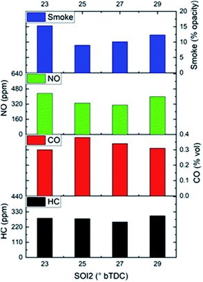
The effect of SOI 2 timing change on emission characteristics of the engine is shown in Fig. 10. It can be observed that by advancing the SOI 2 timing from 21° bTDC, the smoke level shows a decreasing trend up to 27° bTDC and later it increases. The early injections allow better mixing and homogeneous mixture preparation due to the availability of more time. Advancing the SOI shows an increase in the NOX emission. The longer ignition delay and combustion of more accumulated fuel have increased the heat release rate and in-cylinder temperature favoring the formation of more NOX. By advancing the SOI 2, CO emission shows a decreasing trend due to the increase in the cylinder temperature and CO to CO2 conversion. The HC emission shows a marginal increase by advancing the SOI 2 timings. Considering the combustion and emission characteristics, the acceptable SOI 2 angle is observed to be 27° bTDC.
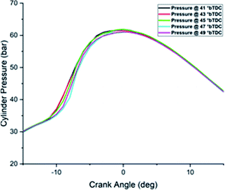
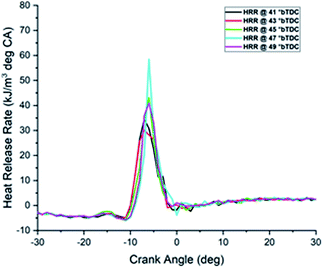
Advancing SOI 1 retards the peak cylinder pressure and heat release rate due to lower compression pressure, temperature, possible wall wetting and; poor atomization which has influenced the start of combustion. The increase in heat release peak by advancing the SOI 1 is due to more fuel accumulation during the increased delay period.
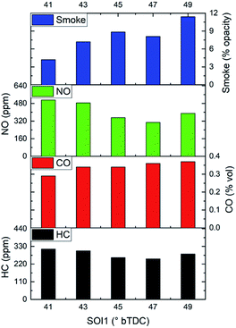
The effect of SOI 1 timing change on emission characteristics of the engine is shown in Fig. 13. It can be observed that by advancing the SOI 1 timing from 41° bTDC, the smoke level shows an increasing trend due to the poor quality of combustion and delayed SOC. Advancing the SOI 1 shows a decreasing trend in the NOX emission and it is observed minimum at 47° bTDC due to lower combustion temperature. By advancing the SOI 1, CO emission shows an increasing trend due to decreased cylinder temperature and poor quality combustion. The HC emission shows an increasing trend proportional to the SOI 1 advance due to the low compression pressure, temperature, high latent heat of evaporation of n-pentanol, and a possible wall wetting. Considering the combustion and emission characteristics, the acceptable SOI 1 angle is observed to be 47° bTDC.
3.3 Combined effect of EGR, multiple injections, and varying PFI fraction
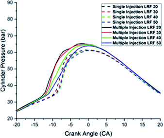
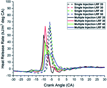
After optimizing the best operating points with EGR and multiple injections, further experiments were conducted to investigate the combined effect of EGR fraction and multiple injections strategies by maintaining the EGR and multiple injection angles of HRF constant and varying the PFI fuel fraction from 20% to 50% in identical operating conditions. The HRF B20 split mass was 30%, 30% & 40% for SOI 1, SOI 2, and SOI 3 respectively. The cooled EGR fraction was maintained at 25%, constant intake temperature of 40 °C and the HRF split injections were fixed at 47°, 27° and 17° bTDC for SOI 1, SOI 2 and SOI 3 respectively at 400 bar injection pressure. The single injection of HRF was maintained at 15° bTDC and PFI of LRF was maintained as same as 355° aTDC.Fig. 14 and 15 shows the cylinder pressure and the heat release profile of n-pentanol karanja B20 RCCI operation with EGR, multiple injections, PFI fraction on cylinder pressure and heat release rate with and without split injections. It can be observed that the peak cylinder pressure increases with multiple injections owing to the homogeneous mixing of the charge and better combustion. As the mass fraction of n-pentanol is increased, the peak cylinder pressure shows a decreasing trend. This is because of the lower combustion temperature, lower calorific value, and the cooling effect of n-pentanol due to the higher latent heat of evaporation. The drop in-cylinder peak pressure is due to the drop in-cylinder temperature owing to the lower heating value and cooling effect of n-pentanol.
From Fig. 16, it can be observed that the HRR is lower with EGR and multiple injections. The heat capacity effect of exhaust gases and higher latent heat of n-pentanol lowered the cylinder temperature. The multiple injections have allowed better charge mixing and lowered the ignition delay to further reduce the HRR. The increase in n-pentanol fraction has reduced the heat release rate mainly because of the lower cylinder temperature, higher latent heat, and lower heating value of n-pentanol.
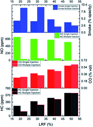
Fig. 16 shows the emission characteristics of B20 RCCI operation with EGR, multiple injections, and PFI fraction with and without split injections. It can be observed that the smoke emission is high at a lower fraction of n-pentanol with EGR and with multiple injections of HRF and it gradually reduces with an increase in n-pentanol mass fraction.
Smoke reduction of 76% is observed with a 40% fraction of n-pentanol. The combined effect of EGR, better charge mixing, and the additional fuel bound oxygen in n-pentanol has reduced the smoke emissions. A significant reduction of 91.5% in NOX emission is observed with multiple injections, EGR, and an increased fraction of n-pentanol from 20% to 40%. Further, when the PFI fraction is increased to 50%, the smoke emission is found to be the lowest. The combined effect of EGR, multiple injections, latent heat of n-pentanol is reduction in cylinder temperature and heat release rate to lower the NOX emission. The CO and HC emission are lower with multiple injections than with single injection but shows an increasing trend with an increasing fraction of n-pentanol. The reduction in the cylinder temperature is due to the increased heat capacity effect of exhaust gases, high latent heat of n-pentanol and the lower oxidation rate has caused the increase in CO and HC emissions.
The major objective of the present work was to investigate the effect of n-pentanol and karanja–diesel B20 blend on combustion and emission in an RCCI engine. Concerning the RCCI engine combustion, the injection variables such as injection timing, dwell between injections, and operating parameters such as EGR, PFI fractions were investigated. It was observed that with the increasing proportion of exhaust gas in the combustion chamber, the combustion deteriorated as a result of the dilution effect and heat capacity effect of EGR. This was observed in lower and delayed pressure and HRR curves. Though there was a substantial decrease in NOX emissions, there was an increase in HC and smoke emission. The advancement of injection angle SOI 1, SOI 2 and SOI 3 had a similar effect on cylinder pressure and HRR rate. With an advanced injection angle, both peak pressure and HRR advanced and increased in amplitude owing to better mixing of air–fuel. A drop in smoke emission and an increase in NOX emissions is observed for advances in SOI 2 and SOI 3 injection angles. In the case of SOI 1, with advanced injection angle, smoke increased and NOX reduced because of lower pressure and temperature during the early compression stroke. With optimized SOI 1, SOI 2, SOI 3 injection angles, and proportion of EGR, the test engine was operated at 400 bar injection pressure by varying the PFI fraction at 50% load and the results were compared to a single injection operation. Smoke and NOX emissions reduced simultaneously especially at a higher PFI fraction. The HC and CO emissions were also comparatively lower than single injection of HRF fuel. The pressure and HRR curves advanced with EGR and multiple injections owing to earlier injection and improved mixture proportion.
4 Conclusions
The bioenergy has the potential to augment future energy requirements. The n-pentanol and biodiesel are promising mineral diesel surrogates due to their higher cetane value, energy density, and viscosity besides being renewable alternatives. Acceptable engine performance using biodiesel and biodiesel blends is a well-established fact since it supports an earlier start of combustion, shorter ignition delay, longer combustion duration, and lower heat release rate. The major objective of this study is the experimental investigation on the performance of a modified diesel engine with PFI and CRDI capability to run in RCCI mode using karanja biodiesel B20 fuel as the HRF and n-pentanol as the LRF by incorporating EGR and multiple injections. From the experimental results, the following conclusions are made.(i) The EGR fraction in the charge will increase the heat capacity of the working fluid and will reduce the flame temperature. Moreover, the endothermic dissociation reactions of the EGR components such as water vapor will also reduce the flame temperature. Considering the peak cylinder pressure, heat release rate, and the emission characteristics of NOX and smoke opacity, the optimum EGR at 400 bar injection pressure and 50% load is 25%.
(ii) The optimized injection timings of HRF SOI 1, SOI 2, and SOI 3 are observed to be 47°, 27°, and 17° bTDC respectively at 400 bar injection pressure considering the acceptable ringing intensity and emissions.
(iii) Higher smoke emission is observed at a lower fraction of n-pentanol with EGR and multiple injections of HRF but gradually reduced with an increase in n-pentanol mass fraction. Smoke reduction of 76% is observed with a 40% energy fraction of n-pentanol compared to a single injection of HRF.
(iv) A significant reduction of NOX emission by about 91.5% is observed with multiple injections, EGR, and an increased fraction of n-pentanol from 20% to 40%. Further, when the PFI fraction was increased to 50%, the least smoke emission is observed.
(v) The emission of CO and HC is lower with multiple injections than single injection but showed an increasing trend with an increasing fraction of n-pentanol.
The experimental investigation showed that the combined effect of EGR and multiple injections strategies have significantly influenced the RCCI engine combustion characteristics like cylinder temperature and heat release rate for the simultaneous reduction of NOX and smoke emission compared to the CDC operation. Hence the production and application of longer-chain alcohol like pentanol and biodiesel from non-edible feedstocks make them a promising alternative renewable transportation fuel.
Author contributions
Sabu V. R.: conceptualization, experimental setup & methodology, investigation, validation, formal analysis, writing—original draft preparation, Justin Jacob Thomas: software, resources, data curation, writing—review and editing, Dr G. Nagarajan – visualization, supervision, project administration, review, and editing.Conflicts of interest
The authors declare no conflict of interest. No external agencies or funders had any role in the design of the study; in the collection, analyses, or interpretation of data; in the writing of the manuscript, or in the decision to publish the results.Acknowledgements
The authors would like to express sincere gratitude to the Centre for Research, Anna University, Chennai, India for supporting the research by granting the AICTE QIP Scholar stipend from July 2013 to June 2016 (Lr.No.QIP/PhD/Admn/AR 1). The authors also acknowledge the support in kind by M/s. Delphi TVS, Chennai, and M/s. Mahindra & Mahindra Ltd (Light motor division) for supplying fuel injection system components used in the experimental setup.References
- CSO, Energy statistics 2019 (twenty sixth issue), 2019, online, available: http://www.mospi.nic.in/sites/default/files/publication_reports/EnergyStatistics2019-finall.pdf.
- L. Chapman, Transport and climate change: a review, J. Transp. Geogr., 2007, 15(5), 354–367, DOI:10.1016/j.jtrangeo.2006.11.008.
- H. Huang, et al., Influence of n-butanol-diesel-PODE 3-4 fuels coupled pilot injection strategy on combustion and emission characteristics of diesel engine, Fuel, 2019, 236, 313–324, DOI:10.1016/j.fuel.2018.09.051.
- R. D. Reitz and G. Duraisamy, Review of high efficiency and clean reactivity controlled compression ignition (RCCI) combustion in internal combustion engines, Prog. Energy Combust. Sci., 2015, 46, 12–71, DOI:10.1016/j.pecs.2014.05.003.
- S. L. Kokjohn, R. M. Hanson, D. a. Splitter and R. D. Reitz, Fuel reactivity controlled compression ignition (RCCI): a pathway to controlled high-efficiency clean combustion, Int. J. Engine Res., 2011, 12(3), 209–226, DOI:10.1177/1468087411401548.
- R. Opat, et al., Investigation of mixing and temperature effects on HC/CO emissions for highly dilute low-temperature combustion in a light-duty diesel engine, SAE Tech. Pap., 2007, vol. 724, pp. 776–790, DOI:10.4271/2007-01-0193.
- L. Tong, H. Wang, Z. Zheng, R. Reitz and M. Yao, Experimental study of RCCI combustion and load extension in a compression ignition engine fueled with gasoline and PODE, Fuel, 2016, 181, 878–886, DOI:10.1016/j.fuel.2016.05.037.
- J. Li, W. Yang and D. Zhou, Review on the management of RCCI engines, Renewable Sustainable Energy Rev., 2017, 69, 65–79, DOI:10.1016/j.rser.2016.11.159.
- B. Tesfa, F. Gu, R. Mishra and a. D. Ball, LHV predication models and LHV effect on the performance of CI engine running with biodiesel blends, Energy Convers. Manage., 2013, 71, 217–226, DOI:10.1016/j.enconman.2013.04.005.
- Y. Li, et al., Parametric study and optimization of a RCCI (reactivity controlled compression ignition) engine fueled with methanol and diesel, Energy, 2014, 65, 319–332, DOI:10.1016/j.energy.2013.11.059.
- M. Krishnamoorthi, R. Malayalamurthi, Z. He and S. Kandasamy, A review on low-temperature combustion engines: performance, combustion, and emission characteristics, Renewable Sustainable Energy Rev., 2019, 116, 109404, DOI:10.1016/j.rser.2019.109404.
- J. M. Bergthorson and M. J. Thomson, A review of the combustion and emissions properties of advanced transportation biofuels and their impact on existing and future engines, Renewable Sustainable Energy Rev., 2015, 42, 1393–1417, DOI:10.1016/j.rser.2014.10.034.
- U. Asad, P. Divekar, M. Zheng and J. Tjong, Low-Temperature Combustion Strategies for Compression-Ignition Engines: Operability limits and Challenges, SAE Tech. Pap., 2013, DOI:10.4271/2013-01-0283.
- K. Anand, R. D. Reitz, E. Kurtz and W. Willems, Modeling Fuel and EGR effects under conventional and low-temperature combustion conditions, Energy Fuels, 2013, 27(12), 7827–7842, DOI:10.1021/ef401989c.
- T. Subramanian, E. G. Varuvel, L. J. Martin and N. Beddhannan, Effect of lower and higher alcohol fuel synergies in biofuel blends and exhaust treatment system on emissions from CI engine, Environ. Sci. Pollut. Res., 2017, 24(32), 25103–25113, DOI:10.1007/s11356-017-0214-9.
- J. Campos-Fernández, J. M. Arnal, J. Gómez and M. P. Dorado, A comparison of performance of higher alcohols/diesel fuel blends in a diesel engine, Appl. Energy, 2012, 95, 267–275, DOI:10.1016/j.apenergy.2012.02.051.
- K. Lawyer, et al., Blend ratio optimization of fuels containing gasoline blendstock, ethanol, and higher alcohols (C3-C6): part i - methodology and scenario definition, SAE Tech. Pap., 2013, vol. 2, DOI:10.4271/2013-01-1144.
- C. V. Manojkumar, J. J. Thomas, V. R. Sabu and G. Nagarajan, Reduced Chemical Kinetic Mechanism for a Waste Cooking Oil Biodiesel/n-Pentanol Mixture for Internal Combustion Engine Simulation, Energy Fuels, 2018, 32(12), 12884–12895, DOI:10.1021/acs.energyfuels.8b02792.
- M. Lapuerta, R. García-Contreras, J. Campos-Fernández and M. P. Dorado, Stability, lubricity, viscosity, and cold-flow properties of alcohol-diesel blends, Energy Fuels, 2010, 24(8), 4497–4502, DOI:10.1021/ef100498u.
- L. Li, J. Wang, Z. Wang and J. Xiao, Combustion and emission characteristics of diesel engine fueled with diesel/biodiesel/pentanol fuel blends, Fuel, 2015, 156, 211–218, DOI:10.1016/j.fuel.2015.04.048.
- L. Wei, C. S. Cheung and Z. Huang, Effect of n-pentanol addition on the combustion, performance and emission characteristics of a direct-injection diesel engine, Energy, 2014, 70, 172–180, DOI:10.1016/j.energy.2014.03.106.
- N. Yilmaz and A. Atmanli, Experimental assessment of a diesel engine fueled with diesel-biodiesel-1-pentanol blends, Fuel, 2017, 191, 190–197, DOI:10.1016/j.fuel.2016.11.065.
- B. Rajesh Kumar and S. Saravanan, Effect of exhaust gas recirculation (EGR) on performance and emissions of a constant speed di diesel engine fueled with pentanol/diesel blends, Fuel, 2015, 160, 217–226, DOI:10.1016/j.fuel.2015.07.089.
- K. Santhosh, G. N. Kumar, Radheshyam and P. V. Sanjay, Experimental analysis of performance and emission characteristics of CRDI diesel engine fueled with 1-pentanol/diesel blends with EGR technique, Fuel, 2020, 267, 117187, DOI:10.1016/j.fuel.2020.117187.
- M. Pan, et al., Experimental study of the spray, combustion, and emission performance of a diesel engine with high n-pentanol blending ratios, Energy Convers. Manage., 2019, 194, 1–10, DOI:10.1016/j.enconman.2019.04.054.
- M. Balat, “Potential alternatives to edible oils for biodiesel production – a review of current work, Energy Convers. Manage., 2011, 52(2), 1479–1492, DOI:10.1016/j.enconman.2010.10.011.
- R. Estevez, et al., Biodiesel at the crossroads: a critical review, Catalysts, 2019, 9(12), 1033, DOI:10.3390/catal9121033.
- S. Thangaraj and N. Govindan, Evaluating combustion, performance and emission characteristics of diesel engine using karanja oil methyl ester biodiesel blends enriched with HHO gas, Int. J. Hydrogen Energy, 2018, 43(12), 6443–6455, DOI:10.1016/j.ijhydene.2018.02.036.
- V. Sharma and G. Duraisamy, Production and characterization of bio-mix fuel produced from a ternary and quaternary mixture of raw oil feedstock, J. Cleaner Prod., 2019, 221, 271–285, DOI:10.1016/j.jclepro.2019.02.214.
- R. L. Patel and C. D. Sankhavara, Biodiesel production from karanja oil and its use in diesel engine: a review, Renewable Sustainable Energy Rev., 2017, 71, 464–474, DOI:10.1016/j.rser.2016.12.075.
- Z. Zheng, M. Xia, H. Liu, X. Wang and M. Yao, Experimental study on combustion and emissions of dual fuel RCCI mode fueled with biodiesel/n-butanol, biodiesel/2,5-dimethylfuran and biodiesel/ethanol, Energy, 2018, 148, 824–838, DOI:10.1016/j.energy.2018.02.015.
- J. J. Thomas, C. V. Manojkumar, V. R. Sabu and G. Nagarajan, Development and validation of a reduced chemical kinetic model for used vegetable oil biodiesel/1-hexanol blend for engine application, Fuel, 2020, 273, 117780, DOI:10.1016/j.fuel.2020.117780.
- A. Jain, A. P. Singh and A. K. Agarwal, Effect of split fuel injection and EGR on NOx and PM emission reduction in a low-temperature combustion (LTC) mode diesel engine, Energy, 2017, 122, 249–264, DOI:10.1016/j.energy.2017.01.050.
- G. Edara, Y. V. V. Satyanarayana Murthy, J. Nayar, M. Ramesh and P. Srinivas, Combustion analysis of modified light-duty diesel engine under high pressure split injections with cooled EGR, Engineering Science and Technology, an International Journal, 2019, 22(3), 966–978, DOI:10.1016/j.jestch.2019.01.013.
- D. Ganesh, P. R. Ayyappan and R. Murugan, Experimental investigation of iso-butanol/diesel reactivity controlled compression ignition combustion in a non-road diesel engine, Appl. Energy, 2019, 242, 1307–1319, DOI:10.1016/j.apenergy.2019.03.166.
- M. T. Garcia, F. J. Jiménez-Espadafor Aguilar, J. a. Becerra Villanueva and E. C. Trujillo, Analysis of a new analytical law of heat release rate (HRR) for homogenous charge compression ignition (HCCI) combustion mode versus analytical parameters, Appl. Therm. Eng., 2011, 31(4), 458–466, DOI:10.1016/j.applthermaleng.2010.09.025.
- J. Benajes, S. Molina, A. García and J. Monsalve-Serrano, Effects of direct injection timing and blending ratio on RCCI combustion with different low reactivity fuels, Energy Convers. Manage., 2015, 99, 193–209, DOI:10.1016/j.enconman.2015.04.046.
| This journal is © The Royal Society of Chemistry 2020 |

