 Open Access Article
High-performance aqueous sodium-ion battery using a hybrid electrolyte with a wide electrochemical stability window†
Yanxin Shen‡
a,
Xiaonan Han‡a,
Tonghui Cai‡a,
Haoyu Hua,
Yanpeng Lia,
Lianming Zhao a,
Han Hub,
Qingzhong Xuea,
Yi Zhaoc,
Jin Zhou
 c,
Xiuli Gao*b,
Wei Xing
 *ab and
Xiaoning Wanga
aState Key Laboratory of Heavy Oil Processing, School of Material Science and Engineering, China University of Petroleum, Qingdao 266580, P. R. China. E-mail: xingwei@upc.edu.cn
bInstitute of New Energy, China University of Petroleum, Qingdao 266580, P. R. China. E-mail: xlgao@upc.edu.cn
cSchool of Chemistry and Chemical Engineering, Shandong University of Technology, Zibo 255049, P. R. China
First published on 6th July 2020
Abstract
The practical application of aqueous sodium-ion batteries (ASIBs) is limited by the electrolysis of water, which results in a low working voltage and energy density of ASIBs. Here, a NaClO4-based acetonitrile/water hybrid electrolyte (NaClO4(H2O)2AN2.4) is applied to ASIBs for the first time, which effectively extends the electrochemical stability window (ESW) to 3.0 V and reduces the internal resistance of the battery. Based on this hybrid electrolyte, an ASIB full cell using carbon coated Na2.85K0.15V2(PO4)3 and NaTi2(PO4)3 as the cathode and anode materials, respectively, can afford a discharge capacity and energy density of 52 mA h g−1 and 51 W h kg−1, respectively, at a current density of 1 A g−1. The energy density of this battery exceeds almost all reported traditional ASIBs.
Large-scale storage of electricity is one of the key problems in the development of new energy technology. Sodium-ion batteries have gained increasing attention, because of the greater abundance and lower cost of Na as compared to Li.1 However, the use of flammable and toxic organic electrolytes has safety issues and these must be handled with care to avoid explosion due to overheating /overcharging. In addition, these electrolytes have low conductivity and high cost. A simple way to achieve a low-cost, safe battery is to replace the organic electrolyte with an aqueous electrolyte.2,3 However, the study of ASIBs is still in the primary stage and there are many problems to be solved. One of the most difficult problems is the fact that the electrolytic potential of water in the electrolyte is 1.23 V (hydrogen evolution potential is 2.297 V and oxygen evolution potential is 3.527 V vs. Na+/Na, at pH = 7). The redox potentials of electrodes should lie in between the hydrogen and oxygen evolution potentials to avoid the electrolysis of water, but this limits the increase of the working voltage of ASIBs. Therefore, the energy density of ASIBs is much less than that of organic sodium ion batteries. As a result, the energy density of the ASIBs under study is generally below 40 W h kg−1.4 To solve the above problem, many researchers began to pay attention to high concentrated aqueous electrolytes for ASIBs. Different from dilute electrolytes, the “water in salt” (WIS) is a new type of super-concentrated system, which apparently reduces the content of water and effectively limits the chemical activity of water molecules, thus significantly expanding the electrochemical stability window (ESW) of electrolyte. NaClO4 is a preferred electrolyte salt for ASIBs because the saturated concentration of NaClO4 (16.5 mol kg−1) is the highest among the common sodium salts (CH3COONa: 5.7 mol kg−1, NaCl: 6.1 mol kg−1, NaNO3: 10.3 mol kg−1, Na2SO4: 1.4 mol kg−1).2,5 The saturated NaClO4 electrolyte was reported with a remarkable wide ESW around 2.8 V.6 However, the wettability of the electrolyte with high concentration on the electrode surface is low, which reduces the utilization ratio of the electrode material. In addition, the electrolyte with high concentration has low conductivity, which increases the internal resistance of batteries.
In this work, water/acetonitrile (AN) hybrid electrolyte based on NaClO4 (NaClO4(H2O)2AN2.4) was applied to ASIBs for the first time. AN is an electrochemical inert organic solvent with wide ESW and high dielectric constant that ensures high conductivity of electrolytes.7 Besides, the presence of AN can increase the wettability of electrolyte on the electrode surface. The as-prepared electrolyte can widen the ESW to 3.0 V. Based on this electrolyte, an ASIB full cell using carbon coated Na2.85K0.15V2(PO4)3 small particles (NKVP-SP-C) and NaTi2(PO4)3 (NTP) as the cathode and anode materials, respectively, can afford the discharge capacity and energy density of 52 mA h g−1 and 51 W h kg−1, respectively, at a current density of 1 A g−1. The energy density of this battery exceeds almost all reported traditional ASIBs.
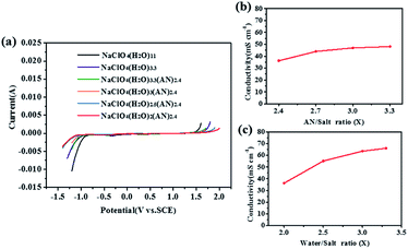
The ESW largely depends on the composition of the electrolyte. The ESW of the electrolytes with different composition were determined by linear sweep voltammetry tests. As shown in Fig. 1a, the saturated 17 M NaClO4 electrolyte (NaClO4(H2O)3.3) had an ESW of 2.55 V, which was larger than that of 5 M NaClO4 (NaClO4(H2O)11, ∼2.3 V). The introduction of AN further increases the ESW to 3.0 V, as in the case of NaClO4(H2O)xAN2.4 (x = 2). Further decrease in H2O content will result in the crystallization of the salt.
The composition of the electrolyte is also related to the conductivity of the electrolyte. Fig. 1b shows the conductivities of NaClO4(H2O)2ANx electrolytes with different AN-to-salt molar ratios. The content of AN had a slight influence on the conductivity of NaClO4(H2O)2ANx. Considering the electrolyte will be flammable with the rise of AN content, x = 2.4 is a reasonable choice. Conductivities of NaClO4(H2O)xAN2.4 electrolytes with different water-to-salt molar ratios are also shown in Fig. 1c. The higher the H2O content, the higher the conductivity. However, the lowest conductivity of 36.2 mS cm−1 can be still achieved.
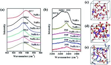
In order to explore the mechanism of the expansion of ESW for the hybrid electrolyte, Raman spectroscopy was used to probe the electrolytes with different compositions (Fig. S1, ESI†, Fig. 2a and b). Fig. 2a illustrates the Cl-O symmetric stretching vibration (ν1) of different electrolytes. In NaClO4 saturated solution, NaClO4(H2O)11, the band of Cl–O symmetric stretching vibration (ν1) occurs at 937.7 cm−1. In comparison, the band of dilute solution (NaClO4(H2O)3.3) and the electrolytes containing AN, underwent a red shift (∼934.4 cm−1). This red shift can be attributed to the transformation of the contact ion pairs of Na+ and ClO4− to solvent separated ion pairs.8 The spectra of O–H stretching vibration of H2O molecules in different electrolytes are shown in Fig. 2b. The NaClO4(H2O)11 displayed three peaks (3227.6 cm−1, 3428.2 cm−1 and 3532.5 cm−1) that are partially overlapped. The peaks of 3227.6 and 3428.2 cm−1 were characteristic of the hydrogen-bonded free water molecules, and the peak at 3532.5 cm−1 was attributed to H2O molecules coordinated with Na+.9 In contrast, NaClO4(H2O)2(AN)2.4 only had one peak at 3550.5 cm−1, and this means that almost all of the water molecules in the solution were coordinated with the Na+. In addition, the peak value blue shifts from 3540.9 cm−1 to 3550.5 cm−1 as the concentration of the solution increases. This should be attributed to the regulated interplay among H2O, –ClO4 and AN with the rise of NaClO4 concentration.
Furthermore, density function theory molecules dynamics (DFT-MD) simulations were conducted to achieve a theoretical insight into the electrolyte structure. In NaClO4(H2O)11 electrolyte (Fig. 2c), the majority of water molecules were in the free water state and were bonded by hydrogen bonds. In NaClO4(H2O)3.3 electrolyte (Fig. 2d), there were still some water molecules that existed as free water molecules. In contrast, there were almost no free water molecules in NaClO4(H2O)2(AN)2.4 electrolyte (Fig. 2e). Besides, Na+ ions were mainly attached to AN and water molecules and the interaction force between Na+ and ClO4− was weakened because of the presence of AN. This result is consistent with the results of the Raman test.
To determine the effectiveness of the hybrid electrolyte in high voltage ASIBs, we assembled the coin cell using Na3V2(PO4)3 (NVP), NTP and NaClO4(H2O)2AN2.4 as the cathode material, anode material and electrolyte, respectively. Although NVP has a high theoretical specific capacity (≈117 mA h g−1), its large particle size, inferior cyclic stability and low conductivity limit its practical electrochemical performance as a cathode material in ASIBs.10,11 We optimized NVP material in three aspects: (1) reduce its particle size by introducing N,N-dimethylformamide (DMF) in the preparation; (2) dope K+ to increase its interstitial void, resulting in better cyclic stability; (3) coat a carbon layer to improve its conductivity. This synthetic strategy is presented in Fig. S2 (ESI†). The X-ray diffraction pattern, refined X-ray diffraction pattern, EDS maps, HRTEM and micrograph of NKVP-SP-C can be found in Fig. S3a–e (ESI†). The Fig. S3f (ESI†) shows the micrograph of NKVP.
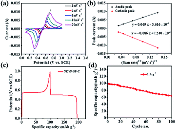
The electrochemical behavior of NKVP-SP-C was investigated by cyclic voltammetry (CV) and constant current charge–discharge in a half cell using Pt plate and SCE (saturated calomel electrode) as the counter electrode and the reference electrode, respectively. CV curves of the NKVP-SP-C electrode at different scan rates from 1 to 20 mV s−1 are shown in Fig. 3a. The potential of the anodic peak increased and the potential of the cathodic peak decreased with increasing scan rate, which indicates greater polarization at higher scan rates. At the same time, the intensity of anodic and cathodic peaks increased with the increase of scan rate (ν). As shown in Fig. 3b, the peak current Ip and ν1/2 are in a linear relationship, which indicates that the electrode reaction of NKVP-SP-C is mainly controlled by ion diffusion. The apparent diffusion coefficient of Na+ was estimated according to the classic Randles–Sevcik equation:12
| Ip = 2.69 × 10⁵n3/2AD1/2Cν1/2 | (1) |
Corresponding to the redox peaks in the CV curve, the potential platform can be observed at the constant charge–discharge curve (Fig. 3c). Based on the galvanostatic charge–discharge measurement, cycle performance was obtained (Fig. 3d). The first discharge specific capacity of NKVP-SP-C was 97.8 mA h g−1. After 100 cycles, it maintains 63.9 mA h g−1 (65.3%).
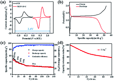
To design a full cell based on the NaClO4(H2O)2AN2.4 electrolyte, the redox potential of anode material NTP was also investigated in this hybrid electrolyte by CV. It is shown in Fig. 4a that both NTP and NKVP-SP-C exhibited a pair of redox peaks in good symmetry, which can be ascribed to the reversible conversion of Ti4+ /Ti 3+ couple and V3+ /V4+ couple.15,16 Accordingly, the full cell comprising the NTP anode and the NKVP-SP-C cathode will have an effective working voltage of 2.4 V. Fig. S4 (ESI†) depicts the CV curve of the full cell at the scanning rate of 5 mV s−1. The potential interval between the cathodic and anodic peaks was 0.18 V, suggesting the full cell has low electrochemical polarization and good reversibility.
The galvanostatic charge–discharge curve of the full cell (Fig. 4b) shows a discharge voltage platform at about 1.2 V. The specific capacity of the full cell can achieve 52 mA h g−1 (calculated on the basis of the total mass of both cathode and anode materials), which is higher than full cells using other cathode materials, such as NaMnO2,17 Na3V2O2x(PO4)2F3−2x,18 Na3V2(PO4)3,19 K0.27MnO2,20 Na0.66[Mn0.66Ti0.34]O2,5 Na2NiFe(CN)6,21 Na2CuFe(CN)6,22 Na0.44MnO2.23 Based on the mass of active electrode materials used, the energy density of this battery was calculated to be 51 W h kg−1, which is higher than those of almost all traditional ASIBs,17,23 as illustrated in Fig. S5 (ESI†).
Fig. 4c depicts the rate capability of the full cell. When the current density increased from 0.5 to 5 A g−1, the full cell retains 60.4% of its initial capacity at 0.5 A g−1. Then, the full cell ran another 100 cycles at 5 A g−1 with high coulomb efficiency (>99%) and mild capacity fade (79.3% of capacity retention).
Fig. 4d shows the cycling performance of the full cell (NKVP-SP-C//NTP) at the current density of 1 A g−1. The specific capacity of the full cell can maintain 60.2% of initial capacity after 100 cycles. Nyquist plot of the full cell before and after 100 cycles is shown in Fig. S6 (ESI†). After 100 cycles, the resistance remains almost constant, indicating a small and stable internal resistance of the full cell due to the high conductivity of the hybrid electrolyte.
Conclusions
In summary, the hybrid electrolyte NaClO4(H2O)2AN2.4 was successfully developed for ASIBs, and its ESW can reach 3.0 V. Based on this electrolyte, an ASIB full cell comprising NKVP-SP-C cathode and NTP anode can afford the energy density as high as 51 W h kg−1, which surpasses all reported traditional ASIBs. This work provides profound insights into the rational design of electrolyte to achieve high energy density ASIBs.Conflicts of interest
There are no conflicts to declare.Notes and references
- K. Nakamoto, R. Sakamoto, Y. Sawada, M. Ito and S. Okada, Small Methods, 2018, 3, 1800220 CrossRef.
- D. Bin, F. Wang, A. G. Tamirat, L. M. Suo, Y. G. Wang, C. S. Wang and Y. Y. Xia, Adv. Energy Mater., 2018, 8, 1703008 CrossRef.
- Y. D. Zhang, Y. F. An, J. M. Jiang, S. Y. Dong, L. Y. Wu, R. R. Fu, H. Dou and X. G. Zhang, Chem. Rev., 2014, 114, 11788 CrossRef PubMed.
- H. X. Yang and J. F. Qian, J. Inorg. Mater., 2013, 28, 1165 CrossRef CAS.
- L. M. Suo, O. Borodin, Y. S. Wang, X. H. Rong, W. Sun, X. L. Fan, S. Y. Xu, M. A. Schroeder, A. V. Cresce, F. Wang, C. Y. Yang, Y. S. Hu, K. Xu and C. S. Wang, Adv. Energy Mater., 2017, 7, 1701189 CrossRef.
- K. Nakamoto, R. Sakamoto, M. Ito, A. Kitajou and S. Okada, Electrochemistry, 2017, 85, 179 CrossRef CAS.
- Q. Y. Dou, Y. L. Lu, L. J. Su, X. Zhang, S. L. Lei, X. D. Bu, L. Y. Liu, D. W. Xiao, J. T. Chen, S. Q. Shi and X. B. Yan, Energy Storage Materials, 2019, 23, 603 CrossRef.
- Y. H. Zhang and C. K. Chan, J. Phys. Chem. A, 2003, 107, 5956 CrossRef CAS.
- Q. Y. Dou, S. L. Lei, D. W. Wang, Q. N. Zhang, D. W. Xiao, H. W. Guo, A. P. Wang, H. Yang, Y. L. Li, S. Q. Shi and X. B. Yan, Energy Environ. Sci., 2018, 11, 3212 RSC.
- W. X. Song, H. S. Hou and X. B. Ji, Acta Phys.-Chim. Sin., 2017, 33, 103 CAS.
- X. H. Zhang, X. H. Rui, D. Chen, H. T. Tan, D. Yang, S. M. Huang and Y. Yu, Nanoscale, 2019, 11, 2556 RSC.
- L. D. Zhang, T. Huang and A. S. Yu, J. Alloys Compd., 2015, 646, 522 CrossRef CAS.
- G. Q. Li, D. L. Jiang, H. Wang, X. Z. Lan, H. H. Zhong and Y. Jiang, J. Power Sources, 2014, 265, 325 CrossRef CAS.
- X. H. Liang, X. Ou, F. H. Zheng, Q. C. Pan, X. H. Xiong, R. Z. Hu, C. H. Yang and M. L. Liu, ACS Appl. Mater. Interfaces, 2017, 9, 13151 CrossRef CAS PubMed.
- S. I. Park, I. Gocheva, S. Okada and J. Yamaki, J. Electrochem. Soc., 2011, 158, A1067 CrossRef CAS.
- H. B. Huang, S. H. Luo, C. L. Liu, Y. Yang, Y. C. Zhai, L. J. Chang and M. Q. Li, Appl. Surf. Sci., 2019, 487, 1159 CrossRef CAS.
- Z. G. Hou, X. N. Li, J. W. Liang, Y. C. Zhu and Y. T. Qian, J. Mater. Chem. A, 2015, 3, 1400 RSC.
- P. R. Kumar, Y. H. Jung, C. H. Lim and D. K. Kim, J. Mater. Chem. A, 2015, 3, 6271 RSC.
- Q. Zhang, C. Y. Liao, T. Y. Zhai and H. Q. Li, Electrochim. Acta, 2016, 196, 470 CrossRef CAS.
- Y. Liu, Y. Qiao, W. X. Zhang, H. H. Xu, Z. Li, Y. Shen, L. X. Yuan, X. L. Hu, X. Dai and Y. H. Huang, Nano. Energy, 2014, 5, 97 CrossRef CAS.
- P. Marzak, J. Yun, A. Dorsel, A. Kriele, R. Gilles, O. Schneider and A. S. Bandarenka, J. Phys. Chem. C, 2018, 122, 8760 CrossRef CAS.
- X. Y. Wu, M. Y. Sun, Y. F. Shen, J. F. Qian, Y. L. Cao, X. P. Ai and H. X. Yang, ChemSusChem, 2014, 7, 407 CrossRef CAS PubMed.
- Z. Li, D. Young, K. Xiang, W. C. Carter and Y. M. Chiang, Adv. Energy Mater., 2013, 3, 290 CrossRef CAS.
Footnotes |
| † Electronic supplementary information (ESI) available: Experimental details, SEM and TEM images, XRD and Raman spectra, EDS and TGA curves, and electrochemical supplemental data. See DOI: 10.1039/d0ra04640j |
| ‡ Shen Yanxin, Han Xiaonan and Cai Tonghui contribute equally to this work. |
| This journal is © The Royal Society of Chemistry 2020 |


