 Open Access Article
Thin, stretchable, universal wireless power transfer system for electric vehicle charging
Yibing Guoab,
Han Zhangcde,
Hao Liuaf,
Shuang Liae,
Shizhen Yinag,
Peng Caoh,
Lijuan Zhang *ai,
Xuecheng Ping*b and
Liang Guo*a
aState Key Laboratory of Nonlinear Mechanics, Institute of Mechanics, Chinese Academy of Sciences, Beijing 100190, China. E-mail: guoliang@imech.ac.cn
bCollege of Mechanical Engineering, Tianjin University of Science and Technology, Tianjin 300222, China. E-mail: xuechengping@hotmail.com
cKey Laboratory of Noise and Vibration, Institute of Acoustics, Chinese Academy of Sciences, Beijing 100190, China
dState Key Laboratory of Acoustics, Institute of Acoustics, Chinese Academy of Sciences, Beijing 100190, China
eSchool of Engineering Science, University of Chinese Academy of Sciences, Beijing 100049, China
fInstitute of Mechanics, Chinese Academy of Sciences, Beihang University (BUAA), Beijing 100191, China
gDepartment of Engineering Systems and Environment, University of Virginia, Charlottesville, VA 22904, USA
hCollege of Architecture and Civil Engineering, Beijing University of Technology, Beijing 100124, China
iBeijing Graphene Institute, Beijing 100094, China. E-mail: zhanglj@bgi-graphene.com
First published on 24th September 2020
Abstract
Wireless power transfer technology has emerged as a new class of prospective components for electric vehicle charging. However, conventional wireless power transfer systems often suffer from unsatisfactory charging efficiency due to the comparatively longer recharge range and insufficient universality for various car models. Here, we present a stretchable wireless power transfer (SWPT) system that consists of thin and stretchable inductive coupling coils designed in serpentine shapes to provide stretchablility for the charging of any model. The receiving coil is adhered to the vehicle roof, and the transmitting coil hung over the vehicle is used to adjust the transmission distance. In order to improve the capability of coils, the design of windings is optimized to enhance stretchability and decrease the resistance via fabricating treble strand serpentine copper traces. The results show that the charging efficiencies of the SWPT remain stable even though the coils are under bending and stretching. As an application demonstration, the SWPT system is installed on the roofs of two different model cars, respectively, and the results demonstrate that the charging efficiencies remain stable. Thus, this work paves a novel way to develop a stretchable, convenient, universal, and high-performance wireless power transfer system.
1. Introduction
For energy conservation and pollution reduction, electric vehicles have been carried out for decades.1–4 One of the challenges of electric vehicles is the charging method of batteries, and researchers have been working on the improvement of the performance and convenience of the charging method for a long time. Meanwhile, the methods of charging are always researched to improve performance and convenience.5–9 The wireless power transfer systems which have demonstrated many advantages such as wirelessness, and being waterproof, dustproof and weatherproof are gaining considerable attention for pure and plug-in hybrid electric vehicles.10–13 The main scheme of wireless charging is usually to install the transmitting coil and module on the ground and the receiving coil on the chassis of the vehicle.14–16 However, there are many obstacles limiting the application of wireless power transfer technology for electric vehicles charging.17–19 Many literatures had reported several important parameters, which affect inductive transmission, such as the distance between transmitting coil and receiving coil, the frequency of transmission current, the alignment of inductive coils and the design of coils.20–23 The distance between the vehicle's chassis and ground is long, resulting in the leakage magnetic flux and low charging efficient, and the different distances between the chassis of different vehicles and the ground cause unstable charging efficient.24–26 In addition, it is difficult for most drivers to park at the accurate location to satisfy a good alignment of the two coils, and hence, this human factor decrease the charging efficiency.27–29 Moreover, some debris around the charging pad such as metal objects, cigarette packs, and gum wrappers could result in lower charging efficiency and even fire accidents due to eddy current.30–32 Therefore, wireless charging technology still faces great challenges in efficiency, convenience, safety and universal applications for electric vehicles.33,34In this paper, we develop a novel wireless power transfer system with a thin, stretchable and inductive coils. The receiving coil is integrated into the vehicle roof and has the ability for the conformal contact with the various models due to the geometric characteristics of thin and stretchability. The transmitting coil is hanged over the vehicles and could be controlled individually to adjust the alignment and distance to receiving coils. This design could eliminate the perplexity of alignment for driver and shorten the distance between the two coils which can lead to the reduction of the leakage magnetic flux and the improvement of the charging efficiency. In addition, the system is easy to clean and rarely disturbed by other sundries because it is installed it on the vehicles roof, which can improve the safety. The coils can maintain stable power transfer efficiency even if subjected to bend or stretch. Moreover, this novel SWPT system demonstrates the unique advantages of outstanding charging efficient and universality and shows the potential applications for electric vehicles charging.
2. Results and discussion
It is well known that the wireless power transfer system basically consists of the inductive coupling between transmitting coil and receiving coil. The transmitting coil is powered through a powder electronic converter, which provides a high-frequency current and a high-frequency magnetic field. The field coupling with the receiving coil allows the wireless transfer of electrical power. Then, a rectification stage converts the signal to DC for charging the battery of vehicle.35–37 It is obvious that the coils, as the primary medium, play a key role in achieving the wireless power transfer, and thus the design of coils can affect the transfer efficiency directly. Fig. 1a exhibits a novel wireless power transfer system and its schematic diagram. The receiving coil is integrated into the car roof, and the transmitting coil is fixed by holding its four corners to cover the receiving coil and could be moved up, down, left, right, forward and backward to adjust the alignment. This design vastly shortens the transmitting distance and keeps the alignment of the two coils to avoid the decrease of inductive efficiency. Moreover, the coil is made of thin serpentine copper traces and hence can be bended and stretched, as shown in Fig. 1b. These features of coil allow it to conform to the car roofs of different vehicle types when charging. An expended view of the structure of coil is shown in Fig. 1c, where the coil has a multilayer configuration of induction coil/insulation layer/induction coil, encapsulated with Ecoflex on the up and down.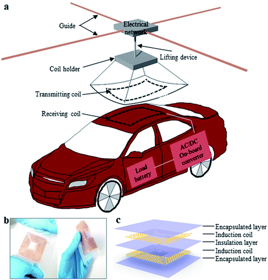 | ||
| Fig. 1 (a) The schematic of SWPT system for electric vehicles; (b) photography of the bended and stretched coil; (c) expanded-view schematic illustration of the various constituents of the coil. | ||
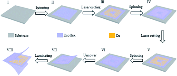
Fig. 2 outlines the fabrication process of an inductance coil, which is realized by microprocessing strategies, involving laser cutting serpentine copper traces to forming a windings, putting the windings on the Ecoflex substrate, coating Ecoflex as insulation layer on the upside of the windings, putting another windings with opposite spiral direction on the insulation layer and encapsulating the top coil with Ecoflex. Details appear in the Experimental section.
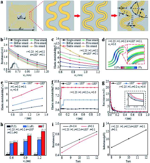
Generally, the inductive wireless power transfer system is excitated by high frequency alternating current. However, the excitation process comes with the skin effect, which leads to low current density and high resistance due to lots of current concentrating upon the surface of the wires of coil.38,39 However, an effective method could be applied to reduce the effect greatly by dividing the wire into multiple strand wires.40,41 In view of this, the winding of stretchable inductance coil is optimized to be multi-strand serpentine copper traces to reduce the influence of skin effect and improve the inductive performance, as shown in Fig. 3a. The conductive coil is designed in a square, as shown in Fig. 3a (left), the outside length dout is 73 mm, and the inside length is din which is obtained after determining the relevant parameters of winding as following. The windings consist of single strand, bifilar strand and treble stranded serpentine copper traces, respectively, and the total width of serpentine copper traces (wt) in one winding keeps constant. The specific design parameters are marked in Fig. 3a (right), d is the distance between two windings, θ is the central angle of serpentine copper traces, r is the arc radius of one winding, w is the width of a serpentine copper traces, s is the space between the two serpentine copper traces, and l is the length of straight segment in serpentine copper traces.
The performance of stretchable conductive coils mainly involves two factors: one is stretchability, the other is quality factor. The quality factor (Q) which reflects the electrical performance of the coil is calculated as following:42
 | (1) |
The coil is made of two layer of the same windings which are multiperiodic serpentine copper traces. The AC resistance (R) of coil is calculated in a representative unit cell as following:
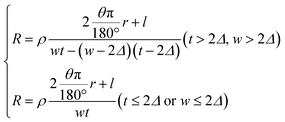 | (2) |
 | (3) |
In eqn (3),43 the μ and γ are 4π × 10−7 H m−1 and 58 × 106 S m−1 obtained from performance manual of copper materials, respectively, and the f is 180 kHz as working frequency. The AC resistances of serpentine copper traces are calculated by eqn (2) and (3).
Fig. 3b shows the resistances of single, bifilar, treble, four, five, and six strand copper traces calculated from the representative unit cell illustrated in the inset (r is 1.25 mm, l is 1 mm, s is 0.2 mm, θ is 150°, and t is 0.1 mm). The results demonstrate the resistances slightly reduce with the increasing of the total width wt of copper traces. Then the stretchability of six kinds copper traces are simulated by FEA, as shown in Fig. 3c. It can be seen that wt is an important factor to affect the stretchability of windings, and the more strand winding has obvious advantages over other. The results show the AC resistance reducing slightly, which has a slight influence on the quality factor (Q) of inductive coil. Although the stretchability increases with the increase of the number of strand, the coil consisting of treble strand serpentine copper traces is enough to accommodate car roofs with different radians. In addition, the fabrication of more strand serpentine copper traces is more complicated. Therefore, the treble strand winding as optimal design is chosen and further studied. Fig. 3d shows the strain distribution of the treble strand winding (wt is 0.6 mm) under 6.17% tensile strain (Fig. 3c). There is an obvious stress concentration on the arc of the serpentine copper traces. Thus, the central angle (θ) and the arc radius (r) of serpentine copper traces are the critical influence factors of stretchability. Fig. 3e shows the stretchability improves with the increasing of r (from 0.8 mm to 1.5 mm) when θ is 120°, 150° and 180°, respectively. Among these three central angles, coil could obtain the maximum stretchability at 180° and minimum one at 120°. Here, r = 1.25 mm is a design parameter. Fig. 3f demonstrates the stretchability of treble strand serpentine copper traces keeps stable once the thickness t exceeds 0.1 mm. Similarly, coil can obtain the maximum stretchability when θ = 180°.The thickness of serpentine copper traces could affect the flexibility of the inductance coils directly, and the thickness 0.1 mm is the optimal choice for the coil design. The resistance of copper traces is a key factor for the quality factor of coil and is inversely proportional to the quality factor according to eqn (1). It is necessary to calculate the resistance of treble strand serpentine copper traces again to evaluate the design parameters according to eqn (2). Where r is 1.25 mm, l is 1 mm, s is 0.2 mm, wt is 0.6 mm, t is from 0 to 1.0 mm, and θ is assigned to 120°, 150° and 180°, respectively. The results illustrate the resistance rapidly reduces with t when 0 < t < 0.2 mm, and the resistance of copper traces obtains the maximum value when θ = 180° (inset), as shown in Fig. 3g. In view of this, to optimize both the stretchability and the resistance of copper traces, the central angle 150° is chosen.
Some design parameters of winding have been discussed and determined, including t = 0.1 mm, θ = 150°, r = 1.25 mm. In addition, l and s keep 1 mm and 0.2 mm, respectively. Meanwhile, the distance (d) between the two adjacent windings is determined as zero, which is illustrated in Fig. 3a (right). wt is a vital parameter which can affect the turns and Q of coil within a set area, when the treble strand windings are fabricated as a square coil with the side length of 73 mm. 0.6 mm, 0.9 mm and 1.2 mm are chosen as the total width of treble strand winding to fabricate coils according to the process described in Fig. 2. The resistance (R) and inductance (L) of these coils are measured, and the quality factor (Q) is calculated by eqn (1). These results are exhibited in Fig. 3h, implying the Q increases with the enlarging of wt. Fig. 3c demonstrates the relationship of wt and stretchability of treble strand winding, illustrating the stretchability reduces with the enlarging of wt. Hence, to optimize both the quality factor and the stretchability of the coil, the wt of 0.9 mm is chosen. The total length of the winding in a coil decreases with the increasing of d, leading to the reduction of resistance of coil. Two overlapping coils (d = −0.4 mm and d = 0.1 mm) are fabricated according to the fabrication process (Fig. 2). Fig. 3i exhibits the actual measured resistance is lower when d is 0.1 mm. The square coil with the side length of 73 mm have 6 turns when d = 0.1 mm, and the receiving and transmitting coils are developed by overlapping two square coil, respectively. 0.1 mm is determined for d. Fig. 3j shows the inductive performance of optimized coil, and the results illustrate that more turns can lead to a better inductive performance.
The thin, stretchable inductive coil is fitted on the vehicle roof charging for many kinds of vehicle types, where the coil size is 73 mm × 73 mm, the resonance frequency of the coil is 180 kHz. And the influence of charging efficiency coming from the deformation of the coil, such as bending and stretching, is a vital point to realize the university of SWPT system. Some experiments were carried out to verify the influence of charging efficiency produced by the deformation of coil. Fig. 4a shows the coils are attached on cylindrical models with different radius of curvature (30–50 mm) to measure the charging efficiency with different load resistances. The result implies the charging efficiencies has hardly changed under bending, even compared with the state of plane, as shown in Fig. 4b. It is well known that the coil not only is bended, but also stretched as it is used to vehicle roof. Therefore, it is necessary to test the charging efficiencies under the state of both bending and stretching. The coil was bended and stretched to conform to the cambered surface of a hemisphere with a radius of 100 mm, and the state of tensile is simulated by FEA (Fig. 4c). The charging efficiency has no change compared with that of coil in the plane, as shown in Fig. 4d. Moreover, in order to simulate the actual charging process, the coil is put on two different model car roofs for testing the charging performance (Fig. 4e). Fig. 4f demonstrates the charging efficiency of the coil has barely affected by the model of car and the maximum charging efficiencies are more than 50%. All the above tests prove the stretchable inductive coil is universal to the charging of any models. For the practical applications, the coils will be scaled up to match the size of real car models by just increasing the turns. Meanwhile, the processing modules and resonant circuits will have corresponding adjustment according to the relative characteristics of the enlarged transmitting and receiving coils such as resistance and inductance to avoid to reducing charging efficiency.
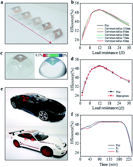 | ||
| Fig. 4 The charging efficiencies of the stretchable coil on (a) and (b) cylinders with different curvature radii, (c) and (d) hemisphere, (e) and (f) two car roofs with different radii. | ||
3. Conclusion
The SWPT system different from the traditional wireless charging method was designed to improve the charging efficiency and realize universality to any vehicles. The receiving coil was integrated on the car roof for cleaning easily and enhancing safety, and the transmitting coil was hung over the car to adjust the position for shortening the distance of reductive transmission, decreasing leakage magnetic flux and improving the power transfer efficiency. The treble strand serpentine copper traces were used to fabricate the inductive coils of SWPT system for obtaining a satisfactory stretchability, which was beneficial to the conformal contact to various vehicle models. Some experiments had proved that the charging efficiency of the SWPT system was affected hardly when the coil was bended or stretched. These results reveal the significance of combining the new installation methods of the wireless charging system with structural engineering of coil to realize a novel stretchable wireless charging system for convenient and universal application to electric vehicle.4. Experimental section
4.1 Fabrication process of stretchable coil
The receiving or transmitting coils consisted of two overlapping stretchable windings. The winding was designed to be a square with the side length of 73 mm (dout) and 6 turns in total. The winding consisted of treble strand serpentine copper traces with the width of 0.3 mm (w) for one of treble strand copper traces, the 0.1 mm thickness (t), the space between the two serpentine copper traces of 0.2 mm (s), the radian of serpentine copper traces of 150° (θ), the length of tangential path in serpentine copper traces of 1 mm (l), the arc radius of one winding of 1.25 mm (r), and the distance between two windings of 0.1 mm (d). Finally, there was a square with the side length of 23 mm (din) in the center of coil. The coil was prepared by laser cutting the copper foil according to dimension parameter. The device was fabricated starting from the substrate that was coating a layer Ecoflex of 0.1 mm thickness on a clean glass panels (Fig. 2I, II), then putting the prepared coil of copper on it (Fig. 2III). A new layer Ecoflex was coated on the first coil to insulate the second coil (Fig. 2IV, V). The entire device was peeled off the glass after coating the Ecoflex at the top as encapsulation layer (Fig. 2VI–VIII).4.2 Simulating stretchability by FEA
The finite element simulation was conducted in Abaqus, a widely accepted commercial software. The compliant elastomeric substrates, Ecoflex (C10 = 0.008054, C01 = 0.002013, D1 = 2.0), were treated as hyper elastic materials depicted by the Mooney-Rivlin model, and copper were treated as ideal elastic plastic materials. The Young's modulus, Poisson's ratio, and yield stress of copper are 124 GPa, 0.34, and 372 MPa, respectively. The hexahedron elements C3D8R were adopted for the substrates, and the shell element S4R was adopted for copper.Conflicts of interest
The authors declare that they have no known competing financial interests or personal relationships that could have appeared to influence the work reported in this paper. The authors declare the following financial interests/personal relationships which may be considered as potential competing interests.Acknowledgements
The authors gratefully acknowledge the support of National Natural Science Foundation of China under grant No. 51975411, No. 11772349 and No. 11972354. This work was supported by the Tianjin Natural Science Foundation of China under grant No. 18JCYBJC88500, and the Personnel Training Plan for Young and Middle-aged Innovation Talents in Universities in Tianjin, China.References
- Z. Dai, J. Wang, M. Long and H. Huang, Energies, 2017, 10, 323 CrossRef.
- M. Liu, Y. Choi, L. Yang, K. Blinn, W. Qin, P. Liu and M. Liu, Nano Energy, 2012, 1, 448–455 CrossRef CAS.
- L.-H. Bjornsson and S. Karlsson, Appl. Energy, 2015, 143, 336–347 CrossRef.
- E. R. Grijalva and J. M. Lopez Martinez, Energies, 2019, 12, 1–31 CrossRef.
- M. Taiebat and M. Xu, J. Cleaner Prod., 2019, 230, 794–797 CrossRef.
- Z. Bi, R. De Kleine and G. Keoleian, J. Ind. Ecol., 2016, 21, 344–355 CrossRef.
- Z. Li, K. Song, G. Wei, J. Jiang and C. Zhu, IEEE Trans. Power Electron., 2016, 32, 1 Search PubMed.
- X. Lu, P. Wang, D. Niyato, D. Kim and Z. Han, IEEE Commun. Surv. Tutor., 2016, 18, 1413–1452 Search PubMed.
- T. Imura, T. Yasuda, K. Oshima, T. Nayuki, M. Sato and A. Oshima, IEEJ Trans. Electr. Electron. Eng., 2016, 11, S91–S99 CrossRef.
- A. Kurs, A. Karalis, R. Moffatt, J. D. Joannopoulos, P. Fisher and M. Soljacic, Science, 2007, 317, 83–86 CrossRef CAS.
- Z. Khan, S. Khan, M. Chowdhury, I. Safro and H. Ushijima-Mwesigwa, Comput. Aided Civ. Infrastruct. Eng., 2019, 34, 547–568 CrossRef.
- N. Mohamed, F. Aymen, M. Ben Hamed and S. Lassaad, Energy Storage, 2020, 2, e117 CrossRef.
- L. Sun, D. Ma and H. Tang, Renewable Sustainable Energy Rev., 2018, 91, 490–503 CrossRef.
- Y. Hsieh, Z. Lin, M. Chen, H. Hsieh, Y. Liu and H. Chiu, IEEE Transactions on Circuits and Systems II: Express Briefs, 2017, 64, 942–946 Search PubMed.
- W. Dghais and M. Alam, Mobile Network Appl., 2016, 23, 1151–1164 CrossRef.
- P. Joseph and E. Devaraj, Journal of Energy Storage, 2018, 16, 145–155 CrossRef.
- J. He, H.-J. Huang, H. Yang and T.-Q. Tang, Phys. A, 2017, 481, 119–126 CrossRef.
- Y. D. Chung, E. Park, W. Lee and J. Lee, IEEE Transactions on Applied Superconductivity, 2018, 1 Search PubMed.
- S. Li and C. Mi, Emerging and Selected Topics in Power Electronics, IEEE Journal of, 2015, 3, 4–17 Search PubMed.
- Z. Luo and X. Wei, IEEE Trans. Ind. Electron., 2017, 1 Search PubMed.
- J. Xu, Y. Xu and Q. Zhang, Comput. Electr. Eng., 2019, 80, 106470 CrossRef.
- K. Aditya, Electrical Engineering, 2018, 100, 1819–1826 CrossRef.
- M. Z. Chaari, Design and production of a system for wireless charging the battery, 2018 Search PubMed.
- C. Zheng, J.-S. Lai and L. Zhang, IEEE Trans. Power Electron., 2015, 30, 1 Search PubMed.
- J. Acero, C. Carretero, I. Lope, R. Alonso, O. Lucia and J. Burdio, Industrial Electronics, IEEE Transactions on, 2013, 60, 410–420 Search PubMed.
- D. Kim, H. Kim, A. Huang, Q. He, H. Zhang, S. Ahn, Y. Zhu and J. Fan, Energies, 2019, 12, 4797–4808 CrossRef.
- K. A. Kalwar, M. Aamir and S. Mekhilef, Measurement, 2018, 118, 237–245 CrossRef.
- D. Wu, Q. Sun, X. Wang and F. Yang, IET Power Electronics, 2018, 11, 781–786 CrossRef.
- J. Y. Seong and S. Lee, Energies, 2019, 12, 4689 CrossRef.
- S. Y. Jeong, H. G. Kwak, G. C. Jang, S. Y. Choi and C. T. Rim, IEEE Trans. Power Electron., 2018, 33, 7387–7397 Search PubMed.
- X. Ren, R. Corcolle and L. Daniel, Eur. Phys. J.: Appl. Phys., 2016, 73, 20902 CrossRef.
- L. Xiao, M. Li, W. J. Cheng, H. W. Fan, G. Liu and Y. H. Sun, Int. J. Appl. Electromagn. Mech., 2016, 52, 1433–1441 Search PubMed.
- P. Machura and Q. Li, Renewable Sustainable Energy Rev., 2019, 104, 209–234 CrossRef.
- B. Zhang, R. Carlson, J. Smart, E. Dufek and B. Y. Liaw, eTransportation, 2019, 2, 100012 CrossRef.
- M. Kiani, B. Lee, P. Yeon and M. Ghovanloo, IEEE J. Solid-State Circuits, 2015, 50, 1–10 Search PubMed.
- C. Panchal and S. Stegen, Engineering Science and Technology, an International Journal, 2018, 21, 922–937 CrossRef.
- V. Cirimele, M. Diana, F. Freschi and M. Mitolo, IEEE Trans. Ind. Appl., 2018, 54, 4069–4079 Search PubMed.
- J. Liu, Q. Deng, D. Czarkowski, M. K. Kazimierczuk, H. Zhou and W. Hu, IEEE Trans. Power Electron., 2019, 34, 2355–2363 Search PubMed.
- H. Igarashi, IEEE Trans. Magn., 2017, 53, 1–7 Search PubMed.
- M. Kiani, U.-M. Jow and M. Ghovanloo, IEEE Transactions on Biomedical Circuits and Systems, 2012, 5, 579–591 Search PubMed.
- C. Sullivan, IEEE Trans. Power Electron., 1999, 14, 283–291 Search PubMed.
- A. Karalis, J. D. Joannopoulos and M. Soljačić, Ann. Phys., 2008, 323, 34–48 CAS.
- O. M. O. Gatous and J. Pissolato, IEE Proceedings-H: Microwaves, Optics and Antennas, 2004, 151, 212–216 Search PubMed.
| This journal is © The Royal Society of Chemistry 2020 |

