 Open Access Article
Porous lithium cobalt oxide fabricated from metal–organic frameworks as a high-rate cathode for lithium-ion batteries†
Hao Weia,
Yuan Tian a,
Yongling An
 a,
Jinkui Feng
 *a,
Shenglin Xiong
 b and
Yitai Qianb
aKey Laboratory for Liquid-Solid Structural Evolution & Processing of Materials (Ministry of Education), School of Materials Science and Engineering, China. E-mail: jinkui@sdu.edu.cn
bSchool of Chemistry and Chemical Engineering, Shandong University, Jinan 250061, China
First published on 28th August 2020
Abstract
Porous materials have many applications, such as energy storage, as catalysts and adsorption etc. Nevertheless, facile synthesis of porous materials remains a challenge. In this work, porous lithium cobalt oxide (LiCoO2) is fabricated directly from Co-based metal–organic frameworks (MOFs, ZIF-67) and lithium salt via a facile solid state annealing approach. The temperature affect on the microstructure of LiCoO2 is also investigated. The as-prepared LiCoO2 shows a uniform porous structure. As a cathode for a lithium-ion battery (LIB), the LiCoO2 delivers excellent stability and superior rate capability. The as-prepared porous LiCoO2 delivers a reversible capacity of 106.5 mA h g−1 at 2C and with stable capacity retention of 96.4% even after 100 cycles. This work may provide an alternative pathway for the preparation of porous materials with broader applications.
1. Introduction
Owing to their special 3D structure, porous materials play an important role in energy storage, catalysis, adsorption and many other fields.1–3 The lack of a facile preparation route for porous materials is one of the key restrictions for their wide application. Various methods have been developed to obtain porous materials, such as the template method, sol–gel and dealloying etc.4,5 However, facile fabrication of porous materials remains a great challenge.The lithium-ion battery (LIB) is one of the most promising power sources for electronics and electric vehicles.6 LiCoO2, as one of the most successful cathode materials for LIBs, and has always been promising in the field since the commercialization of LIBs, as it has the advantages of high working potential, high specific capacity and good cycling performance etc.7,8
With the fast development of electronics such as drones, 5G, and electric vehicles, the high rate performance of LIBs becomes an essential property. Great interest and effort has been devoted to improving the rate performance of LIBs. One promising strategy is regulating the cathode structure to become porous. The porous structure could shorten the transport distance of ions, increase the contact between electrode and electrolyte, and buffer the volume expansion.9,10 Porous structured LiCoO2 has been prepared by various methods, such as Li-vapor crystal growth, template synthesis, electrostatic spray deposition, etc., and has proven to improve rate performance.11–13 For example, Mitsunori Kitta et al. obtained the porous LiCoO2 crystal film on the CoO substrate surface by the Li-vapor crystal growth method.14 Ghamouss Fouad et al. prepared a porous LiCoO2 cathode via electrospray deposition.15 Nevertheless, the synthesis of porous LiCoO2 with a facile method still needs further exploration.
The metal–organic framework (MOF) is an emerging kind of porous coordination polymer, which is composed of organic ligands and inorganic moieties. MOFs possess the characteristics of large pore volume and larger surface area. Moreover, the synthesis of MOFs is relatively facile and scalable.16–18 A number of studies in recent years indicate that MOFs could serve as precursors to obtain porous materials.19,20 For example, Yuanyuan Liu et al. have obtained a porous lithium iron phosphate (LiFePO4) composite cathode from an Fe based metal–organic framework (MIL-100 (Fe)).19 The intrinsically porous architecture of MOFs could remain in the final products.
In this work, taking LiCoO2 as an example, a porous oxide-based cathode can be successfully fabricated using Co-based MOFs (ZIF-67) as a precursor via a facile annealing approach. Porous LiCoO2 may provide more contact sites, shorten the pathway of the Li-ion transport, and reduce the negative impact of the volume expansion during high rate charge–discharge. The idea may be extended to the synthesis of other porous alkali metal cathode materials such as lithium manganese oxide, sodium cobalt oxide, and potassium manganese oxide etc.
2. Experimental section
ZIF-67 was synthesized by a solution method based on a previous report.21 All of the reagents were purchased and used without further purification. For the typical synthesis of ZIF-67, 1.45 g cobalt hexahydrate nitrate (Co(NO3)2·6H2O, 99%, Aladdin) and 40 mg cetyltrimethylammonium bromide (CTAB, 90%, Aladdin) were dissolved in 50 mL water to obtain a uniform solution. The solution was rapidly injected into a 350 mL aqueous solution containing 22.7 g 2-methylimidazole (98%, Aladdin). Then the mixture was stirred for another 30 min, and the precipitate was collected by filtering and drying in an oven at 80 °C until a blue color was obtained. For the preparation of LiCoO2, the prepared ZIF-67 was ground for 1 h with lithium hydroxide monohydrate (LiOH·H2O, 98%, Aladdin) (Co/Li 1.0![[thin space (1/6-em)]](https://www.rsc.org/images/entities/char_2009.gif) :
:![[thin space (1/6-em)]](https://www.rsc.org/images/entities/char_2009.gif) 1.02 mol/mol). Then the mixture was heated to 650 °C, 700 °C and 750 °C in the air atmosphere at a rate of 2 °C min−1. Then the mixture was kept at the top temperature for 2 h. The obtained LiCoO2 is black (Fig. S1†). The commercial LiCoO2 is bought from Sigma-Aldrich.
1.02 mol/mol). Then the mixture was heated to 650 °C, 700 °C and 750 °C in the air atmosphere at a rate of 2 °C min−1. Then the mixture was kept at the top temperature for 2 h. The obtained LiCoO2 is black (Fig. S1†). The commercial LiCoO2 is bought from Sigma-Aldrich.
Crystal structures were characterized via X-ray diffraction (XRD, Rigaku Dmaxrc diffractometer) using Cu-Kα radiation between 5° and 90° with a scan rate of 10° min−1. The morphologies and microstructures were measured via scanning electron microscopy (SEM, SU-70) and high-resolution transmission electron microscopy (HR-TEM JEM-2100). The surface area and pore distribution of the as-synthesized samples were estimated by Brunauer–Emmett–Teller theory (BET, ASAP 2020) based on N2 adsorption.
To test the electrochemical performance, the as-synthesized porous LiCoO2 was mixed with Super P and polyvinylidene fluoride (PVDF) (8![[thin space (1/6-em)]](https://www.rsc.org/images/entities/char_2009.gif) :
:![[thin space (1/6-em)]](https://www.rsc.org/images/entities/char_2009.gif) 1
1![[thin space (1/6-em)]](https://www.rsc.org/images/entities/char_2009.gif) :
:![[thin space (1/6-em)]](https://www.rsc.org/images/entities/char_2009.gif) 1 by mass) in NMP for 12 h to obtain a homogeneous slurry. The cathode electrode was prepared by casting it on aluminum foil and drying in a vacuum oven at 80 °C for 24 h. The loading of electrode was about 2 mg cm−2. The solute of the electrolyte was 1 M lithium hexafluorophosphate in ethylene carbonate and diethyl carbonate (EC and DEC, volume ratio 1
1 by mass) in NMP for 12 h to obtain a homogeneous slurry. The cathode electrode was prepared by casting it on aluminum foil and drying in a vacuum oven at 80 °C for 24 h. The loading of electrode was about 2 mg cm−2. The solute of the electrolyte was 1 M lithium hexafluorophosphate in ethylene carbonate and diethyl carbonate (EC and DEC, volume ratio 1![[thin space (1/6-em)]](https://www.rsc.org/images/entities/char_2009.gif) :
:![[thin space (1/6-em)]](https://www.rsc.org/images/entities/char_2009.gif) 1) with 5 wt% fluoroethylene carbonate (FEC). The counter and reference electrode were both lithium foil. The commercial LiCoO2 (99%, Aladdin) electrode was also prepared in the same way. The cell was assembled in the vacuum glove box (Mikrouna Super 1220/750) with water and oxygen content lower than 1 ppm. The electrochemical performance was tested. Cyclic voltammetry (CV) was tested on the electrochemical workstation (CHI660E), and the discharge/charge performance was tested on charge–discharge equipment (Neware) between 3 and 4.2 V at different current densities.
1) with 5 wt% fluoroethylene carbonate (FEC). The counter and reference electrode were both lithium foil. The commercial LiCoO2 (99%, Aladdin) electrode was also prepared in the same way. The cell was assembled in the vacuum glove box (Mikrouna Super 1220/750) with water and oxygen content lower than 1 ppm. The electrochemical performance was tested. Cyclic voltammetry (CV) was tested on the electrochemical workstation (CHI660E), and the discharge/charge performance was tested on charge–discharge equipment (Neware) between 3 and 4.2 V at different current densities.
3. Results and discussion
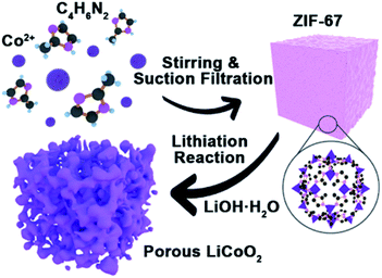
The synthesis process of porous LiCoO2 is simulated in Scheme 1. The ZIF-67 and LiOH·H2O were simply mixed by grinding and heating to 650 °C, 700 °C and 750 °C for 2 h to obtain LiCoO2. It can be predicted that the temperature will inevitably affect the solid-state reaction, which can affect the detailed structure of the porous products.The indexed XRD patterns of the ZIF-67 precursor and as-obtained LiCoO2 are shown in Fig. 1a and b. From the figures, we can see that the XRD pattern of the as-prepared ZIF-67 and LiCoO2 are consistent with the previous reports and standard LiCoO2 patterns (JCPDS card no. 75-0532), which indicates that LiCoO2 can be successfully synthesized from ZIF-67.21,22 BET tests were performed to measure the surface area and pore size distribution of the as-prepared LiCoO2 (Fig. 1c and d). The as-prepared LiCoO2 had an average pore diameter of 7.5 nm and a surface area of around 9.2 m2 g−1. The larger specific surface area and rich pores are beneficial for Li-ion transport, which could benefit the rate performance.23 At the same time, the moderate surface area increase can balance the ion transport and side reactions due to the larger surface area.
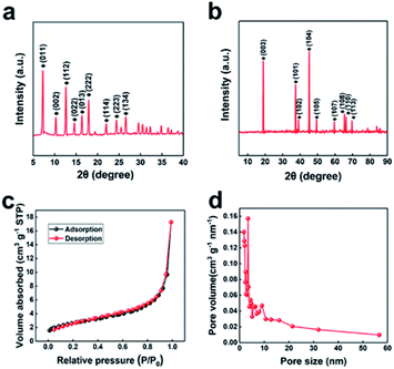 | ||
| Fig. 1 XRD patterns of (a) ZIF-67 and (b) porous LiCoO2, BET of (c) surface area and (d) the pore size distribution of the porous LiCoO2. | ||
The morphology and microstructure of the as-prepared ZIF-67 and LiCoO2 were further probed via SEM and HR-TEM. SEM photographs of the ZIF-67 at different magnifications are shown in Fig. 2a and b. The ZIF-67 displays a uniform cubic shape with an edge length of around 450 nm, which is consistent with previous reports.21 Fig. 2c and d show SEM images of the as-prepared 700 °C LiCoO2 sample. From the figures we can see that the particle size of the as-prepared LiCoO2 is distributed in the range 200–300 nm. The TEM investigation confirms that the as-prepared LiCoO2 is porous (Fig. 2e). From the figure we can see that the 3D porous framework is formed by inter-connected tiny LiCoO2 crystals. The structure could increase the charge transfer between the electrolyte and electrode with good bulk ion transport rate, and shorten the ion transport in the electrode.24 In contrast, the SEM and TEM images of LiCoO2 prepared at 650 °C and 750 °C are also given in Fig. S2–S5.† From the figures (Fig. S2†) we can see that at 650 °C, the as-prepared LiCoO2 has inhomogeneous size and pore distribution. Moreover, from the HR-TEM (Fig. S3†) we can see that the 650 °C LiCoO2 is poorly crystallized, which suggested that 650 °C is not sufficient for the synthesis of well-crystallized LiCoO2. For the LiCoO2 prepared at 750 °C, an aggregated morphology is observed with a smaller pore volume (Fig. S4 and S5†), which suggested that 750 °C is too high for the preparation of porous LiCoO2. This may be due to the swelling of the porous structure when the annealing temperature is higher. A smaller pore volume is not beneficial for lithium ion transport. Fig. 2f shows the HR-TEM images of the as-prepared 700 °C LiCoO2, the lattice constant is consistent with standard LiCoO2. A proper crystal structure of the cathode material is essential for the excellent electrochemical properties. Too high or too low may deteriorate the pore and crystalline structure of LiCoO2. Furthermore, the LiCoO2 electrode after cycling was investigated. It can be seen that no significant change is observed in morphology (Fig. S7†). The porous structure of LiCoO2 remained, which verified that the structure is stable during cycling.
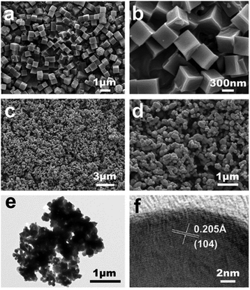 | ||
| Fig. 2 SEM micrographs of (a and b) ZIF-67 (Co) and (c and d) porous LiCoO2 at different magnifications, (e) TEM micrograph and (f) HR-TEM micrograph of porous LiCoO2. | ||
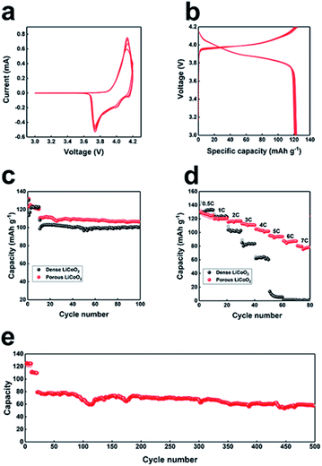
The electrochemical properties of as-prepared LiCoO2 were further examined by CV and static current charge–discharge. For the CV measurement, the LiCoO2 electrode was cycled at a scan rate of 0.5 mV s−1 between 3 V and 4.2 V (Fig. 3a). As we can see, a pair of reversible peaks owing to lithium intercalation and deintercalation in the layered LiCoO2, appeared at 4.15 and 3.75 V, which is typical for LiCoO2. The subsequent curves almost overlap, which implied the high reversibility of the as-prepared porous LiCoO2. The first 10 cycles of charge–discharge curves of LiCoO2 are presented in Fig. 3b at 0.5C, from the figure we can see that the curves almost overlap, confirming the good cycling ability of LiCoO2. Fig. 3c shows the cyclability of the porous and commercial LiCoO2 electrode at a low rate (2C). The porous LiCoO2 shows a higher capacity with similar capacity retention at 2C. The rate performance was further studied in detail to characterize the rate capability of the as-prepared porous LiCoO2, and the results are shown in Fig. 3d. As we initially expected, with increased current density, the porous LiCoO2 delivers reversible capacities of 123 mA h g−1, 120 mA h g−1, 118 mA h g−1, 110 mA h g−1, 102 mA h g−1, 96 mA h g−1, 89 mA h g−1, and 79 mA h g−1 at a current density of 0.5, 1, 2, 3, 4, 5, 6, and 7C, respectively. For commercial LiCoO2, the capacity rapidly decreased as the current density increased. When the current density was 6C, the capacity of commercial LiCoO2 reduced to nearly 0. The superior rate performance may be ascribed to the porous structure of aggregated nanosized LiCoO2 crystals, which ensures a faster charge transfer rate between the electrolyte–electrode and higher ion transport due to the lower ion transport pathway.11–13 Moreover, the porous LiCoO2 electrode also presented a stable long-cycling performance (Fig. 3e) with a capacity retention of 70% even after 500 cycles. The good reversibility implies the stable porous structure of the as-prepared LiCoO2. The charge–discharge profiles at different rate and cycling number are also given (Fig. S6†), from the figure we can see that the voltage profiles are almost the same at a different rate and cycling number, which further confirms the stable structure of the as-prepared LiCoO2.11–13 In addition, the electrochemical performance of the as-synthesized porous LiCoO2 is compared with previously reported work (Table S1†). By comparison, it can be found that the porous LiCoO2 cathode has outstanding performance in terms of rate, cycling stability and reversible capacity.
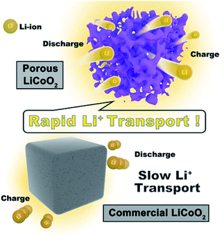
Scheme 2 shows the high rate mechanism of the as-prepared porous LiCoO2 materials. Obviously, the main difference between porous LiCoO2 and commercial LiCoO2 is the robust 3D porous structure, which provides better electrode/electrolyte contact sites to promote charge transfer. Moreover, the special pore structure could shorten the ion transport, which benefits the lithium ion diffusion. Finally, the robust 3D porous structure can reduce the negative impact of the volume changes of LiCoO2 during Li-ion intercalation and de-intercalation at high rates, which would cause the crystal collapse.25–27 The results may be useful for developing other high rate materials.
4. Conclusions
In conclusion, uniform porous LiCoO2 is successfully synthesized with ZIF-67 and lithium salt at 700 °C in 2 h via a simple solid method. The direct utilization of nanosize MOF as a precursor is one of the key merits of this work, which is different from the traditional preparation process for LiCoO2. During the annealing process, the rich porous structure of the precursor is retained, which provides the superior porous structure of as prepared LiCoO2. Moreover, the organic ligand is oxidized to form gases such as water vapor and carbon oxides at a high temperature, which can help pore formation. Additionally, the solid state synthesis process is easier than commercial production. By ensuring faster charge transfer between the electrolyte–electrode, and higher ion transport due to the lower ion transport pathway and robust 3D structure, the porous LiCoO2 electrode exhibits outstanding rate performance and long cycling ability. The high cost of MOF may be a limitation, however, the promising rate performance may enable it to be utilized in special areas. This work may also be useful for the design of other high performance energy storage materials and other functional materials.Conflicts of interest
There are no conflicts to declare.Acknowledgements
This work was supported by the State Key Program of National Natural Science of China (61633015), the National Natural Science Foundation of China (51972198), Taishan Scholars Program of Shandong Province, the Project of the Taishan Scholar (ts201511004, tsqn201812002, ts20190908), and the Young Scholars Program of Shandong University (2016WLJH03).References
- Y. Cheng, Y. Ying, J. Susilo, S. Jiang, T. Chung, S. Zhang and D. Zhao, Adv. Mater., 2018, 47, 1802401 CrossRef PubMed.
- S. Das, P. Heasman, T. Ben and S. Qiu, Chem. Rev., 2017, 117, 1515–1563 CrossRef CAS PubMed.
- J. Liang, Z. Liang, R. Zou and Y. Zhao, Adv. Mater., 2017, 29, 1701139 CrossRef PubMed.
- A. Fu, C. Wang, F. Pei, J. Cui, X. Fang and N. Zheng, Small, 2019, 15, 1804786 CrossRef PubMed.
- Z. Liu, X. Yuan, S. Zhang, J. Wang, Q. Huang, N. Yu, Y. Zhu, L. Fu, F. Wang, Y. Chen and Y. Wu, NPG Asia Mater., 2019, 11, 12 CrossRef.
- M. Li, J. Lu, Z. Chen and K. Amine, Adv. Mater., 2018, 30, 1800561 CrossRef PubMed.
- J. P. Brog, A. Crochet, J. Seydoux, M. J. D. Clift, B. Baichette, S. Maharajan, H. Barosova, P. Brodard, M. Spodaryk, A. Züttel, B. R. Rutishauser, N. H. Kwon and K. M. Fromm, J. Nanobiotechnol., 2017, 15, 58 CrossRef PubMed.
- Z. Tian, H. Yu, Z. Zhang and X. Xu, ChemBioEng Rev., 2018, 5, 111–118 CrossRef CAS.
- M. K. Shobana and Y. Kim, J. Alloys Compd., 2017, 729, 463–474 CrossRef CAS.
- J. Liu, J. Long, S. Du, B. Sun, S. Zhu and J. Li, Nanomaterials, 2019, 9, 441 CrossRef CAS PubMed.
- G. Saat, F. M. Balci, E. P. Alsaç, F. Karadas and Ö Dag, Small, 2018, 14, 1701913 CrossRef PubMed.
- J. Xie, J. Zhao, Y. Liu, H. Wang, C. Liu, T. Wu, P. Hsu, D. Lin, Y. Jin and Y. Cui, Nano Res., 2017, 10, 3754–3764 CrossRef CAS.
- L. Xue, S. V. Savilov, V. V. Lunin and H. Xia, Adv. Funct. Mater., 2018, 28, 1705836 CrossRef.
- M. Kitta and K. Kuratani, Cryst. Growth Des., 2019, 19, 150–156 CrossRef CAS.
- I. Bezza, E. Luais, F. Ghamouss, M. Zaghrioui, F. Tran-van and J. Sakai, J. Alloys Compd., 2019, 805, 19–25 CrossRef CAS.
- Y. V. Kaneti, S. Dutta, M. S. A. Hossain, M. J. A. Shiddiky, K. L. Tung, F. K. Shieh, C. K. Tsung, C. W. Wu and Y. Yamauchi, Adv. Mater., 2017, 29, 1700213 CrossRef PubMed.
- Y. An, H. Fei, Z. Zhang, L. Ci, S. Xiong and J. Feng, Chem. Commun., 2017, 53, 8360 RSC.
- Y. Xue, S. Zheng, H. Xue and H. Pang, J. Mater. Chem. A, 2019, 7, 7301 RSC.
- Y. Liu, J. Gu, J. Zhang, F. Yu, L. Dong, N. Nie and W. Li, J. Power Sources, 2016, 304, 42–50 CrossRef CAS.
- J. Li, H. Zhao, J. Wang, N. Li, M. Wu, Q. Zhang and Y. Du, Nano Energy, 2019, 62, 876–882 CrossRef CAS.
- S. K. Parka, J. K. Kima, J. H. Kimb and Y. C. Kang, Mater. Charact., 2017, 132, 320 CrossRef.
- X. Yang, J. Chen, Y. Chen, P. Feng, H. Lai, J. Li and X. Luo, Nano-Micro Lett., 2018, 10, 15 CrossRef PubMed.
- J. Huang, W. Wang, X. Lin, C. Gu and J. Liu, J. Power Sources, 2018, 378, 677–684 CrossRef CAS.
- Z. Li, X. Feng, L. Mi, J. Zheng, X. Chen and W. Chen, Nano Res., 2018, 11, 4038–4048 CrossRef CAS.
- Q. Liu, M. S. Javed, C. Zhang, Y. Li, C. Hu, C. Zhang, M. Lai and Q. Yang, Nanoscale, 2017, 9, 5509 RSC.
- H. Meng, L. Li, J. Liu, X. Han, W. Zhang, X. Liu and Q. Xu, J. Alloys Compd., 2017, 690, 256–266 CrossRef CAS.
- S. Zhang, X. Li, B. Ding, H. Li, X. Liu and Q. Xu, J. Alloys Compd., 2020, 822, 153624 CrossRef CAS.
Footnote |
| † Electronic supplementary information (ESI) available. See DOI: 10.1039/d0ra05615d |
| This journal is © The Royal Society of Chemistry 2020 |

