 Open Access Article
A novel and fast method to prepare a Cu-supported α-Sb2S3@CuSbS2 binder-free electrode for sodium-ion batteries†
Jing Zhou a,
Qirui Doua,
Lijuan Zhanga,
Yingyu Wanga,
Hao Yuana,
Jiangchun Chenab and
Yu Cao
 *a
*a
aSchool of Chemical Engineering, School of Electrical Engineering, Key Laboratory of Modern Power System Simulation and Control & Renewable Energy Technology, Ministry of Education, Northeast Electric Power University, Jilin 132012, China. E-mail: ycao@neepu.edu.cn
bSchool of Chemistry, Beijing Advanced Innovation Center for Biomedical Engineering, Beihang University, Beijing 100191, China
First published on 11th August 2020
Abstract
Antimony sulfide (Sb2S3) is a promising anode material for sodium-ion batteries due to its low cost and high theoretical specific capacity. However, poor stability and a complex preparation process limit its large-scale application. Herein, we prepare a binder-free composite electrode composed of amorphous (α-) Sb2S3 and copper antimony sulfide (CuSbS2) through a simple closed-space sublimation (CSS) method. When applied as the anode in sodium-ion batteries, the α-Sb2S3@CuSbS2 electrode exhibits excellent performance with a high discharge capacity of 506.7 mA h g−1 at a current density of 50 mA g−1 after 50 cycles. The satisfactory electrochemical performance could be ascribed to the α-Sb2S3–CuSbS2 composite structure and binder-free electrode architecture, which not only retain the structural stability of the electrode but also improve the electrical conductivity. Consequently, CSS, as a scalable and environmentally friendly method, can produce a binder-free electrode in just a few minutes, demonstrating its great potential in the industrial production of sodium-ion batteries. This study may open an avenue to preparing binder-free commercial electrodes.
1. Introduction
Recently, sodium-ion batteries (SIBs) have emerged as powerful alternatives to lithium-ion batteries (LIBs) owing to the high abundance and easy accessibility of sodium resources.1–5 Yet, one of the challenges for constructing high-performance SIBs is the development of novel anode materials with excellent cycling stability and rate performance.6,7 Currently, intensive efforts have been devoted to using metal sulfides as new anode materials for SIBs due to their excellent electrochemical performance.8–12 Among them, antimony sulfide (Sb2S3) has been considered as one of the most promising anode materials for SIBs resulting from its low cost and high theoretical specific capacity (946 mA h g−1).13,14 Zhu et al.15 investigated the flower-like Sb2S3 as an anode for SIBs, which could deliver a maximum reversible capacity of 835.3 mA h g−1. Wu et al.16 reported an Sb2S3 nanoparticle decorated graphene composite through a facile one-step hydrothermal process and the Sb2S3 nanoparticles exhibited the highest reversible capacity for SIBs of 581.2 mA h g−1 at the current density of 50 mA g−1 after 50 cycles. Liu et al.17 via one-step high-shear exfoliation prepared a few layered Sb2S3/carbon sheet composite anode which exhibited good electrochemical performance. But their preparation processes are over complicated and will not be able to meet large-scale industrial production requirements.It is worth noting that the slurry-casting method is widely used in electrode preparation (including the preparation of commercial electrodes), which almost spends long time and has a complicated process. Meanwhile, the most polymer binders (such as polyvinylidene fluoride (PVDF), carboxymethyl cellulose (CMC), polyvinyl alcohol (PVA), poly tetra fluoroethylene (PTFE)) are insulative, which will decrease the conductivity of the electrodes and the cycle stability.18 Besides, the binder will undergo side reactions with the electrolyte during cyclic charge and discharge. For example, PVDF will decompose in the ether electrolyte and produce a large number of –(CH![[double bond, length as m-dash]](https://www.rsc.org/images/entities/char_e001.gif) CF)– groups covering the surface of PVDF, which severely affect the bonding force between the binder and the active material. Therefore, binder-free electrodes may provide a great opportunity for the enhancement of high-performance SIBs. Carbon materials such as graphite, graphene, and carbon nanofiber/nanotube often serve as the current collector to bear active material for avoiding the use of binders.19–21 Another effective solution is to deposit the active material directly on the current collector by electrochemical deposition or chemical deposition, and then to form an integrated electrode without binder.22–24 In contrast, as a common preparation process for polycrystalline thin-film, closed-space sublimation (CCS) method has the characteristics of simple method, short time, and low cost. It has been widely used in the preparation of thin film solar cells.25–27 To our knowledge, there has been no report on preparing ion batteries electrodes with the CCS method.
CF)– groups covering the surface of PVDF, which severely affect the bonding force between the binder and the active material. Therefore, binder-free electrodes may provide a great opportunity for the enhancement of high-performance SIBs. Carbon materials such as graphite, graphene, and carbon nanofiber/nanotube often serve as the current collector to bear active material for avoiding the use of binders.19–21 Another effective solution is to deposit the active material directly on the current collector by electrochemical deposition or chemical deposition, and then to form an integrated electrode without binder.22–24 In contrast, as a common preparation process for polycrystalline thin-film, closed-space sublimation (CCS) method has the characteristics of simple method, short time, and low cost. It has been widely used in the preparation of thin film solar cells.25–27 To our knowledge, there has been no report on preparing ion batteries electrodes with the CCS method.
Herein, we directly prepared the Cu-supported composite electrode composed of amorphous (α-) Sb2S3 and copper antimony sulfide (CuSbS2) in several minutes by the CCS method. It can be used as binder-free electrode for SIBs without any treatment. Compared with the traditional methods, there are no use of binders, poisonous solvents, and other inactive materials as well as time-consuming, high-temperature drying steps during the CSS process. Furthermore, the electrochemical properties of the α-Sb2S3@CuSbS2 electrode were studied. It delivered a reversible capacity of 506.7 mA h g−1 at 0.05 A g−1 and maintained a stable capacity of 497.6 mA h g−1 after 50 cycles at 0.1 A g−1, which displays an satisfactory sodium storage performance. Moreover, we further proved that the CCS method has robust scalability and can be extended to other electrodes. Our work demonstrates a novel and fast preparation method, which is beneficial for the electrode to be large-scale industrial production, which could provide a new idea and direction for the preparation of binder-free electrodes.
2. Experimental section
2.1. Preparation of electrodes
2.2. Characterizations of electrodes
The X-ray diffraction patterns were characterized by a Rigaku D/max 2500 with Cu Kα radiation (λ = 1.5418 Å). The morphology of fabricated electrode was examined using a field-emission scanning electron microscope (Hitachi S-4800). XPS analysis was performed on a Thermo K-Alpha XPS spectrometer (Thermo Fisher Scientific) equipped with a monochromatic Al Kα X-ray source (hγ = 1468.6 eV). Raman spectra were measured on a Renishaw RM1000 microspectroscopic system. A He–Ne laser with a wavelength of 633 nm (Thorlab HRP-170) was used as the excitation laser.2.3. Electrochemical measurements
The electrochemical performance tests were carried out in CR2032 type coin cells at room temperature. The α-Sb2S3@CuSbS2 or traditional electrode were used as the working electrodes, and metallic sodium was employed as the counter electrode. The electrolyte was composed of 1.0 M NaCF3SO3 dissolved in diglyme. The galvanostatic discharge/charge measurements and rate capability tests were carried out on Land battery testing system (CT2001A) with an operating voltage window of 0.01–2.50 V. The cyclic voltammetry (CV) measurement was performed at a scan rate of 0.1 mV s−1 in the potential range of 0.01–2.50 V (versus Na/Na+) with an electrochemical workstation (CHI660E). The electrochemical impedance spectroscopy (EIS) was recorded at a PARSTAT 2263 with a perturbation voltage of 5 mV in the frequency range of 100 kHz to 0.01 Hz.3. Results and discussion
3.1. Characterization
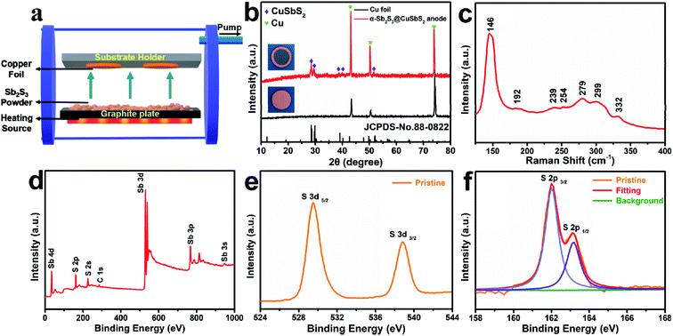
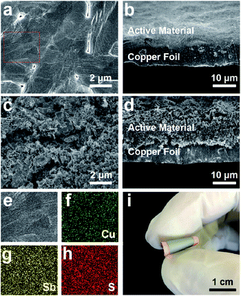
The electrode was fabricated via a facile and cost-effective CSS method in just a few minutes, and the specific experimental details could be seen in the Experimental section. The XRD measurements were performed to obtain more insights into the crystalline structures and compositions of the hybrid electrode (Fig. 1b). Except for the diffraction peaks of pure copper foil, the diffraction peaks of as-prepared electrode at 28.45°, 29.90°, 39.05°, 40.18°, and 52.07° can be ascribed to the orthorhombic phase CuSbS2 (JCPDS no. 88-0822). Since there are no characteristic peaks correspond to the Sb2S3, the deposited Sb2S3 may be of amorphous structure due to the fast growth rate and the absence of substrate temperature.28 To further confirm the composition of the composite electrode, Raman spectrum of as-prepared electrode is shown in Fig. 1c. The shifts at 146 cm−1, 192 cm−1, 239 cm−1, 279 cm−1, 299 cm−1 can be assigned to Sb2S3,29,30 and the most intense band at 146 cm−1 corresponding to the S–Sb–S bending vibrations,31 while the two weak peaks at 254 cm−1 and 322 cm−1 correspond to the vibrations of Cu–S bonds and the v1 symmetric Sb–S stretching vibrations of CuSbS2,32 which implies that a small amount of CuSbS2 is present in the deposited layer of electrode besides Sb2S3. The chemical states of elements and composition of as-prepared product were conducted by X-ray photoelectron spectroscopy (XPS). The survey spectrum in Fig. 1d shows the presence of Sb, S, C without Cu, and the two peaks at 529.48 eV and 538.87 eV in high-resolution spectrum (Fig. 1e) correspond to the Sb 3d5/2 and Sb 3d3/2,33,34 confirming the presence of Sb3+. Besides, the two peaks at 162.02 eV and 163.17 eV (Fig. 1f) correspond to S 2p2/3 and S 2p1/2, respectively, demonstrating that the surface of the composite electrode was covered with amorphous Sb2S3.35 Due to the limited detection depth of XPS on the sample (less than 10 nm),36 there is no bonding energy related to CuSbS2 appearing in the XPS spectrum. Based on the above analysis results, we deduced that the deposited active materials were mainly composed of Sb2S3, and CuSbS2 was mainly distributed at the interface between copper foil and amorphous Sb2S3.The morphology and microstructure of as-prepared electrodes were systematically studied via scanning electron microscope (SEM). The surface and cross-section SEM images of the α-Sb2S3@CuSbS2 electrode, as shown in Fig. 2a and b, the product deposited on the copper foil is a relatively dense film with an average thickness of 6 μm. By contrast, the electrode with the same mass loading by the traditional method is loose (Fig. 2c) and has approximately twice the thickness (12 μm) the α-Sb2S3@CuSbS2 electrode (Fig. 2d). It is generally accepted that smaller electrode thickness symbolizes shorter ions and electrons transmission distance,30 and thus enhances ion and electron diffusion. Additionally, a clear dividing line can be observed between the active substance and the collector, which isn't present in the α-Sb2S3@CuSbS2 electrode. This phenomenon can also explain that the presence of CuSbS2 makes the connection between the active material and the current collector more secure. As presented in the energy-dispersive spectroscopy (EDS) maps (Fig. 2f–h), antimony, sulfur, and copper atoms are homogeneously distributed onto the surface of the α-Sb2S3@CuSbS2 electrode, which indicates the uniformity of the spatial structure. It is worthwhile mentioning that the α-Sb2S3@CuSbS2 electrode is flexible, and there is no cracking or peeling even under extreme bending conditions (Fig. 2i). In addition, it was found that there is no mass loss even after 50 times high-intensity bending. This is due to the α-Sb2S3@CuSbS2 composite structure, which enables the active substance to be closely connected to the current collector through forming CuSbS2. We infer that this stable structure would effectively improve the electrochemical performance of the electrode.
Based on the above results, the deposition process of the α-Sb2S3@CuSbS2 electrode can be schematically illustrated in Fig. 3. At the initial stage of deposition, the sublimated Sb2S3 vapor first encountered the copper foil and reacted with the copper on the surface to form CuSbS2. With processing of the preparation, α-Sb2S3 was deposited on the electrode to finally constitute the α-Sb2S3@CuSbS2 electrode. It is worth noting that there is no clear dividing line between the two materials, since the copper element can be gradually diffused from copper foil into active materials to form CuSbS2. Generally, the loading material of the traditional electrode consists of active material, conductive carbon and binder. After a simple statistical calculation, the content of the active material is generally 0.48–0.91 mg cm−2 (Table S1†), which is consistent with our optimal load of the electrode (0.4–0.6 mg cm−2).
3.2. Electrochemical performance
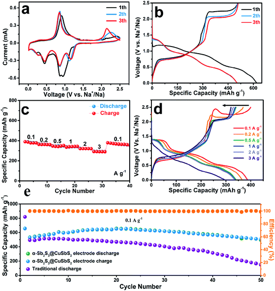
To evaluate the electrochemical properties of the α-Sb2S3@CuSbS2 as anode for the sodium-ion battery, CR2032 type half-cell was fabricated using metallic Na as counter electrode. First, a typical cyclic voltammetry (CV) measurement for the first three cycles was performed to observe the redox behavior (Fig. 4a). Four cathodic peaks can been seen in the first cycle, and there is splitting peaks located at around 0.90 V which composed of the peaks at 0.95 V and 0.85 V, attributed to the conversion reaction of the CuSbS2 (CuSbS2 + 4Na+ + 4e− → Cu + Sb + 2Na2S) and the formation of solid-electrolyte interface (SEI).37 The formation of SEI contributed to the sodium storage capacity, so it caused the merge of the two peaks. In addition, the cathodic peaks at 0.44 V and 0.20 V were attributed to the conversion reaction of the Sb2S3 (Sb2S3 + 6Na+ + 6e− → 2Sb + 3Na2S) and alloying reaction between Na+ and Sb (2Sb + 6Na+ + 6e− → 2Na3Sb), respectively.38 Correspondingly, there are three oxidation peaks (0.90 V, 1.19 V, and 2.40 V) distributed in the first charge. The peak at 0.90 V and 1.19 V correspond to the reversible formation of Sb2S3 (2Na3Sb → 2Sb + 6Na+ + 6e−, 2Sb + 3Na2S → Sb2S3 + 6Na+ + 6e−).39 Besides, the peak centered at 2.40 V is related to the formation of CuSbS2.40 The curve profile of the next cycle profile is significantly different from the first cycle, and it shows that there is an activation step during the first discharge.14 It is worth noting that the oxidation peak at 2.40 V in the first cycle gradually shifted to 2.14 V during the next cycles, and accompanied by process of specific current density rise, indicating the enhanced charge storage of the electrode. This unique behavior of potential change is due to metal copper formed during sodiation process of CuSbS2. But the metal copper produced in the opposite process does not all participate in reversible reactions, which resulting in a large amount of copper residual,37 thus forming a continuous conducting network of copper. It directly leads to the improvement of the electrical conductivity and the increase of the overpotential, which indirectly affects the sodium storage performance of the electrode.41 Meanwhile, copper generated in situ can make the α-Sb2S3@CuSbS2 more firmly anchored to the copper foil.The first three-cycle galvanostatic charge–discharge voltage profiles of the α-Sb2S3@CuSbS2 electrode were measured at a current rate of 50 mA g−1 (Fig. 4b). The initial discharge and charge specific capacities of the α-Sb2S3@CuSbS2 electrode are 617.7 and 507.7 mA h g−1, respectively, with an initial coulombic efficiency of 82.19%. Interestingly, the first plateau, corresponding to the Na+ insertion and SEI formation processes, have a phenomenon of overpotential rise at the initial stage, which may signify that the reaction processes require the activation energy (energy barrier) to proceed and cause the voltage abnormal at the initial stage.42 But there is no similar activation process compared to crystalline materials. This would result in a corresponding decrease in the Coulomb efficiency of the first lap of the α-Sb2S3@CuSbS2 electrode. It is worthwhile mentioning that there is a decreasing process of the platform voltage during the charging process at the first three-cycle, which indicates a good agreement with the results of CV measurements that the shift of oxidation peak at 2.40 V to 2.14 V. For the subsequent cycles, the charge–discharge curve has a good similarity. The Coulomb efficiency remains above 99%, showing the high reversibility and stability of the α-Sb2S3@CuSbS2 electrode.
On the other hand, the rate capability of the α-Sb2S3@CuSbS2 electrode at various current densities was further studied (Fig. 4c). The current density was increased sequentially every 5 cycles from 0.1 A g−1 to 3 A g−1 and then returned to 0.1 A g−1. The reversible capacity of 293.0 mA h g−1 is maintained even at a high current of 3 A g−1. The α-Sb2S3@CuSbS2 electrode possessed the capacity retention of 75.1% when the current density increases 30 times to 3 A g−1, indicating an exceptional rate capability. After reducing the current density back to 0.1 A g−1, a specific capacity of 380.1 mA h g−1 is recovered, demonstrating excellent electrochemical stability.43 Fig. 4d displays the discharge/charge voltage curves for the α-Sb2S3@CuSbS2 electrode at various current densities. Even as the current density is increased from 0.1 to 3.0 A g−1, the discharge/charge voltage curves exhibit similar shapes, exhibiting excellent rate capability.
To illustrate the advantages of the CSS method for electrode preparation, we scraped off the active material loaded on the α-Sb2S3@CuSbS2 electrode, and then added the conductive agent and binder to prepare the traditional electrode by slurry-casting method. Fig. 4e shows the cycle performance of both electrodes at a current rate of 0.1 A g−1. For the α-Sb2S3@CuSbS2 electrode, there is no capacity fade occurs in the first 20 cycles, and delivers a superior capacity retention of 94.9% (compare to the capacity of the second cycle) after 50 cycles with a capacity of 506.7 mA h g−1. The decay of capacity after 20 cycles may result from collapse of electrode material structure, Sb2S3 suffered from large volume expansion ratio of 395% upon Na+ intercalation, which is inevitable. This is also the main obstacle hindering the large-scale application of antimony-based materials in SIBs.44 By contrast, the capacity of traditional electrode decreases rapidly and loses 52.54% of initial capacity after 50 cycles. The different electrochemical performance among the two electrodes could be attributed to the different electrode structure, the Sb2S3–CuSbS2 composite structure, which can ensure the active material to be firmly anchored to the current collector is more conducive to maintaining the stability of performance.
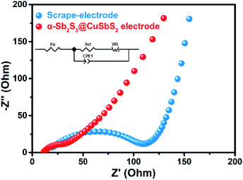
To further investigate the electrochemical behavior of α-Sb2S3@CuSbS2 electrode, electrochemical impedance spectroscopy (EIS) measurement was introduced. Fig. 5 shows the comparison of EIS results of the two electrodes. All the Nyquist plots are composed of one semicircle which relates to the charge transfer resistance (Rct) between the electrode material and electrolyte at high frequency and a straight line which relates to the Na+ diffusion impedance at low frequency. It can be clearly observed that the Rct of α-Sb2S3@CuSbS2 electrode is much smaller than that of the traditional electrode (39.9 Ω vs. 114.4 Ω, Table 1), confirming that the binder-free structure effectively reduces the electronic resistivity of the electrode. Base on the data of EIS and the equation i0 = RT/nFRct, the exchange current density (i0) of α-Sb2S3@CuSbS2 electrode (0.129 mA cm−2) and the i0 of the traditional electrode (0.045 mA cm−2) were calculated, confirming the improved charge-transfer in α-Sb2S3@CuSbS2 electrode.45 We emphasize that avoiding the use of binders is one of key factors to improve electrode performance because the polymer binders can block the active sites, inhibit diffusion and increase transfer resistance of the electron or sodium ion. In addition, the binder will undergo side reactions with the electrolyte during cyclic charge and discharge; for example, PVDF will decompose in the ether electrolyte, the binder-free electrode can also effectively avoid this problem.46,47
| Electrode | Rct (Ω) | i0 (mA cm−2) |
|---|---|---|
| α-Sb2S3@CuSbS2 electrode | 39.9 | 0.129 |
| Traditional electrode | 114.4 | 0.045 |
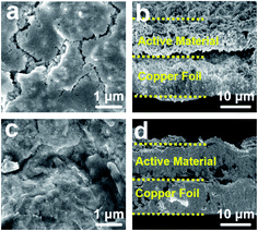
To demonstrate the stability of the α-Sb2S3@CuSbS2 electrode in sodium storage process, the morphological changes of both the α-Sb2S3@CuSbS2 electrode and the traditional electrode were examined after 30 cycles. The cycled traditional electrode suffers a severe loss of active material and appears a lot of cracks (Fig. 6a), which are likely owing to the volume expansion of the material and the failure of the adhesive. Furthermore, the separation between the active material and the current collector can be seen obviously from the cross-section images (Fig. 6b). In contrast, the surface of cycled α-Sb2S3@CuSbS2 electrode covered with the full SEI layer shows negligible cracks (Fig. 6c). The strong SEI layer for better cycling stability of alloying anodes.48 As shown in Fig. 6d, the active material can still keep close contact with the copper foil after 30 cycles. The integrity of electrode contributes to maintaining good cycling stability.49,50 The composite structure of α-Sb2S3@CuSbS2 electrode could ensure close contact between the active material and the current collector, thereby reducing the quality loss in the charge/discharge process. Meanwhile, the ability of copper generated in situ during the charge/discharge process is another crucial factor for ensuring good rate capability and cycling life. The copper not only firmly connects the active material with the current collector, but also improves the conductivity of the electrode.
The satisfactory sodium storage performance of the α-Sb2S3@CuSbS2 electrode could be attributed to the following factors. First, the electrode is composed of only active materials, avoiding the addition of binder or other inactive materials, which has positive effects on improving electrode conductivity.51 Second, α-Sb2S3@CuSbS2 composite material is the key guarantee for the electrode to have excellent performance. The unique structure can enable the active material to be firmly anchored to the current collector without binder. Finally, the CSS preparation process can effectively reduce the electrode thickness and shorten the transport distance of electron and ions, which is critical to the activity and stability of the electrode.45,52 Furthermore, since the capacity of CuSbS2 is much smaller than that of Sb2S3, the main function of CuSbS2 is to stabilize the connection of the current collector and the electrode.53 Therefore, on the basis of achieving the function of CuSbS2, increasing the proportion of Sb2S3 in active materials as much as possible is the key to further improve the performance of SIBs. This is what we will focus on in the future study.
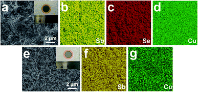
To further confirm a viable electrode fabrication technique, several other materials were prepared by CSS process as active substances including antimony selenide (Sb2Se3) and elemental antimony (Sb) to validate this method suitable for a variety of materials. From the SEM images and EDS results in Fig. 7, one can see that these dense and uniform active material films can be successfully deposited in the copper foil, demonstrating the application potential of CSS process in SIB fabrication.
It should be mentioned that the electrode preparation time of the CSS process is concise a complete electrode can be prepared in just a few minutes. However, the conventional electrode preparation method requires the preparing slurry and drying process, which generally takes a long time of 12–16 hours (Table S2†). Furthermore, the CSS is a solution-free, binder-free fabrication process. The entire preparation process does not require expensive or precise equipment. Hence, it may be easy to achieve large-scale industrial production.
To achieve continuous high-throughput manufacturing for potential practical applications, the roll-to-roll manufacturing technique was conceived to prepare the binder-free electrode (Fig. 8). First, the active material is placed on the heating source with an appropriate sublimation distance under vacuum condition. Then the copper foil directional move driven by the slow controllable rotation of the axis, and simultaneously maintain the appropriate temperature of heating source. Sublimated active material will deposit on copper foil to form binder-free electrodes. This simple method could save many tedious steps like mix electrode materials, cast slurry and dry electrode. Meanwhile, the CSS roll-to-roll process completely avert the use of highly toxic solvent, like N-methyl-2-pyrrolidione (NMP) which is indispensable in traditional fabrication for electrode, effectively avoiding potential environmental pollution. Moreover, the equipment of the CSS roll-to-roll not only takes up less space, but also enables large-scale continuous and fast electrode manufacturing.
4. Conclusions
In summary, a α-Sb2S3@CuSbS2 electrode has been prepared through a simple closed-space sublimation process in an ultrashort time, which can be used as a binder-free anode for SIBs. The result of XRD, Raman, and XPS analyses suggested that the active material is composed of α-Sb2S3 and CuSbS2. The unique structure of electrode ensures close contact of Sb2S3 with collector. Benefiting from the binder-free preparation method and the unique composite structure, the α-Sb2S3@CuSbS2 electrode show satisfactory sodium storage performance with a high reversible capacity of 506.7 mA h g−1 at a current density of 0.05 A g−1 after 50 cycles. Based on the above experiments and conclusions, we have conceived a CSS roll-to-roll device to achieve continuous and fast electrode manufacturing. With the increase of cost and environmental requirements, the CSS process would become a promising binder-free commercial electrode preparation process.Conflicts of interest
There are no conflicts to declare.Acknowledgements
This work was supported by the National Natural Science Foundation of China (NSFC Grant No. 51772049), the ‘Thirteenth Five-Year’ Scientific and Technological Research Project of the Education Department of Jilin Province, China (Grant No. JJKH20190705KJ), and the project of Jilin Development and Reform Commission (Grant No. 2019C042).References
- H. Hou, L. Shao, Y. Zhang, G. Zou, J. Chen and X. Ji, Adv. Sci., 2017, 4, 1600243 CrossRef PubMed.
- B. Qu, C. Ma, G. Ji, C. Xu, J. Xu, Y. S. Meng, T. Wang and J. Y. Lee, Adv. Mater., 2014, 26, 3854–3859 CrossRef CAS PubMed.
- H. Hou, X. Qiu, W. Wei, Y. Zhang and X. Ji, Adv. Energy Mater., 2017, 7, 1602898 CrossRef.
- J. Zhou, J. Chen, M. Chen, J. Wang, X. Liu, B. Wei, Z. Wang, J. Li, L. Gu and Q. Zhang, Adv. Mater., 2019, 31, 1807874 CrossRef PubMed.
- A. Firouzi, R. Qiao, S. Motallebi, C. W. Valencia, H. S. Israel, M. Fujimoto, L. A. Wray, Y. D. Chuang, W. Yang and C. D. Wessells, Nat. Commun., 2018, 9, 861 CrossRef PubMed.
- Y. Yang, D. Yu, H. Wang and L. Guo, Adv. Mater., 2017, 29, 220–228 Search PubMed.
- H. Hou, C. E. Banks, M. Jing, Y. Zhang and X. Ji, Adv. Mater., 2015, 27, 7861–7866 CrossRef CAS PubMed.
- J. Zhou, B. Yan, J. Yang, Y. Yang, W. Zhou, H. Lan, H. Wang and L. Guo, Nanoscale, 2018, 10, 9108–9114 RSC.
- Y. Zhu, J. Li, X. Yun, G. Zhao, P. Ge, G. Zou, Y. Liu, H. Hou and X. Ji, Nano-Micro Lett., 2020, 12, 1–18 Search PubMed.
- T.-E. Fan and H.-F. Xie, J. Alloys Compd., 2019, 775, 549–553 CrossRef CAS.
- S. Li, W. He, B. Liu, J. Cui, X. Wang, D.-L. Peng, B. Liu and B. Qu, Energy Storage Mater., 2020, 25, 636–643 CrossRef.
- J. Yuan, B. Qu, Q. Zhang, W. He, Q. Xie and D. L. Peng, Small, 2020, 1907261 CrossRef CAS PubMed.
- M. Deng, S. Li, W. Hong, Y. Jiang, W. Xu, H. Shuai, H. Li, W. Wang, H. Hou and X. Ji, RSC Adv., 2019, 9, 15210–15216 RSC.
- L. Yang, W. Hong, Y. Tian, G. Zou, H. Hou, W. Sun and X. Ji, Chem. Eng. J., 2020, 385, 123838 CrossRef.
- Y. Zhu, P. Nie, L. Shen, S. Dong, Q. Sheng, H. Li, H. Luo and X. Zhang, Nanoscale, 2015, 7, 3309–3315 RSC.
- F. Wu, X. Guo, M. Li and H. Xu, Ceram. Int., 2017, 43, 6019–6023 CrossRef CAS.
- Y. Liu, Z. Tai, J. Zhang, W. K. Pang, Q. Zhang, H. Feng, K. Konstantinov, Z. Guo and H. K. Liu, Nat. Commun., 2018, 9, 3645 CrossRef PubMed.
- T. Jin, Q. Han and L. Jiao, Adv. Mater., 2020, 32, e1806304 CrossRef PubMed.
- M. Ye, Z. Dong, C. Hu, H. Cheng, H. Shao, N. Chen and L. Qu, Small, 2014, 10, 5035–5041 CAS.
- Y. Liu, X. He, D. Hanlon, A. Harvey, J. N. Coleman and Y. Li, ACS Nano, 2016, 10, 8821–8828 CrossRef CAS PubMed.
- D. J. Kirsch, S. D. Lacey, Y. Kuang, G. Pastel, H. Xie, J. W. Connell, Y. Lin and L. Hu, ACS Appl. Energy Mater., 2019, 2, 2990–2997 CrossRef CAS.
- H. Wang, P. Hu, J. Yang, G. Gong, L. Guo and X. Chen, Adv. Mater., 2015, 27, 2348–2354 CrossRef CAS PubMed.
- X. Li, M. Sun, J. Ni and L. Li, Adv. Energy Mater., 2019, 9, 1901096 CrossRef.
- I. Y. Choi, C. Jo, W.-G. Lim, J.-C. Han and J. K. Kim, ACS Nano, 2019, 13, 6513–6521 CrossRef CAS PubMed.
- J. L. Cruz-Campa and D. Zubia, Sol. Energy Mater. Sol. Cells, 2009, 93, 15–18 CrossRef CAS.
- Y. Cao, X. Zhu, H. Chen, X. Zhang, J. Zhouc, Z. Hu and J. Pang, Sol. Energy Mater. Sol. Cells, 2019, 200, 109945 CrossRef CAS.
- Y. Cao, X. Zhu, J. Jiang, C. Liu, J. Zhou, J. Ni, J. Zhang and J. Pang, Sol. Energy Mater. Sol. Cells, 2020, 206, 110279 CrossRef CAS.
- T. M. Razykov, A. X. Shukurov, O. K. Atabayev, K. M. Kuchkarov, B. Ergashev and A. A. Mavlonov, Sol. Energy, 2018, 173, 225–228 CrossRef CAS.
- Q. Wang, Y. Lai, F. Liu, L. Jiang and M. Jia, Energy Technol., 2019, 7, 1900928 CrossRef CAS.
- R. G. Sotelo Marquina, T. G. Sanchez, N. R. Mathews and X. Mathew, Mater. Res. Bull., 2017, 90, 285–294 CrossRef CAS.
- B. Minceva-Sukarova, G. Jovanovski, P. Makreski, B. Soptrajanov, W. Griffith, R. Willis and I. Grzetic, J. Mol. Struct., 2003, 651, 181–189 CrossRef.
- V. Vinayakumar, S. Shaji, D. Avellaneda, T. K. Das Roy, G. A. Castillo, J. A. A. Martinez and B. Krishnan, Sol. Energy Mater. Sol. Cells, 2017, 164, 19–27 CrossRef CAS.
- J. Grigas, E. Talik and V. Lazauskas, Phase Transitions, 2002, 75, 323–337 CrossRef CAS.
- J. Wang, T. Zhang, Y. Yang, M. Li, Q. Qin, P. Lu, P. Ning and Q. Wang, Energy Fuels, 2019, 33, 1734–1744 CrossRef CAS.
- Y. Liu, Z. Tai, J. Zhang, W. K. Pang, Q. Zhang, H. Feng, K. Konstantinov, Z. Guo and H. K. Liu, Nat. Commun., 2018, 9, 1–10 CrossRef PubMed.
- S. Oswald and W. Brückner, Surf. Interface Anal., 2004, 36, 17–22 CrossRef CAS.
- C. Marino, T. Block, R. Pöttgen and C. Villevieille, J. Power Sources, 2017, 342, 616–622 CrossRef CAS.
- Z. Wu, B. Johannessen, W. Zhang, W. K. Pang, J. Mao, H. K. Liu and Z. Guo, J. Mater. Chem. A, 2019, 7, 12842–12850 RSC.
- A. Darwiche, C. Marino, M. T. Sougrati, B. Fraisse, L. Stievano and L. Monconduit, J. Am. Chem. Soc., 2012, 134, 20805–20811 CrossRef CAS PubMed.
- D. Y. Yu, P. V. Prikhodchenko, C. W. Mason, S. K. Batabyal, J. Gun, S. Sladkevich, A. G. Medvedev and O. Lev, Nat. Commun., 2013, 4, 2922 CrossRef PubMed.
- M. Giorgetti, S. Mukerjee, S. Passerini, J. Mcbreen and W. H. Smyrl, J. Electrochem. Soc., 2001, 148, A768 CrossRef CAS.
- S. M. Hwang, J. Kim, Y. Kim and Y. Kim, J. Mater. Chem. A, 2016, 4, 17946–17951 RSC.
- N. Yu, L. Zou, C. Li and K. Guo, Appl. Surf. Sci., 2019, 483, 85–90 CrossRef CAS.
- X. Xiong, G. Wang, Y. Lin, Y. Wang, X. Ou, F. Zheng, C. Yang, J. H. Wang and M. Liu, ACS Nano, 2016, 10, 10953–10959 CrossRef CAS PubMed.
- K. Cao, H. Liu, Y. Jia, Z. Zhang and L. Jiao, Adv. Mater. Technol., 2017, 2, 1600221 CrossRef.
- I. Kovalenko, B. Zdyrko, A. Magasinski, B. Hertzberg, Z. Milicev, R. Burtovyy, I. Luzinov and G. Yushin, Science, 2011, 334, 75–79 CrossRef CAS PubMed.
- J. K. Papp, J. D. Forster, C. M. Burke, H. W. Kim, A. C. Luntz, R. M. Shelby, J. J. Urban and B. D. McCloskey, J. Phys. Chem. Lett., 2017, 8, 1169–1174 CrossRef CAS PubMed.
- H. Wang, D. Yu, X. Wang, Z. Niu, M. Chen, L. Cheng, W. Zhou and L. Guo, Angew. Chem., Int. Ed. Engl., 2019, 58, 16451–16455 CrossRef CAS PubMed.
- X.-l. Huang, R.-z. Wang, D. Xu, Z.-l. Wang, H.-g. Wang, J.-j. Xu, Z. Wu, Q.-c. Liu, Y. Zhang and X.-b. Zhang, Adv. Funct. Mater., 2013, 23, 4345–4353 CrossRef CAS.
- S. Hariharan, K. Saravanan, V. Ramar and P. Balaya, Phys. Chem. Chem. Phys., 2013, 15, 2945–2953 RSC.
- J. Zhou, Y. Zhou, X. Zhang, L. Cheng, M. Qian, W. Wei and H. Wang, Nanoscale, 2020, 12, 79–84 RSC.
- K. Cao, L. Jiao, Y. Liu, H. Liu, Y. Wang and H. Yuan, Adv. Funct. Mater., 2015, 25, 1082–1089 CrossRef CAS.
- X. Li, M. Sun, J. Ni and L. Li, Adv. Energy Mater., 2019, 9, 1901096 CrossRef.
Footnote |
| † Electronic supplementary information (ESI) available. See DOI: 10.1039/d0ra05623e |
| This journal is © The Royal Society of Chemistry 2020 |

