 Open Access Article
“Water-in-salt” electrolyte enhanced high voltage aqueous supercapacitor with carbon electrodes derived from biomass waste-ground grain hulls†
Mingjun Panga,
Shang Jiang*a,
Jianguo Zhao *a,
Sufang Zhanga,
Runwei Wang
 b,
Ning Lia,
Rui Liua,
Qiliang Pana,
Wenshan Qua and
Baoyan Xinga
aInstitute of Carbon Materials Science, Shanxi Datong University, Datong 037009, P. R. China. E-mail: jiangshang3714@163.com; pangmj0861@163.com
bState Key Laboratory of Inorganic Synthesis and Preparative Chemistry, College of Chemistry, Jilin University, Changchun 130012, P. R. China
First published on 25th September 2020
Abstract
To design high specific surface area and optimize the pore size distribution of materials, we employ a combination of carbonization and KOH activation to prepare activated carbon derived from ground grain hulls. The resulting carbon material at lower temperature (800, BSAC-A-800) exhibits a porous structure with a high specific surface area of 1037.6 m2 g−1 and a pore volume of 0.57 m3 g−1. Due to the synergistic structural characteristics, BSAC-A-800 reveals preferable capacitive performance, showing a specific capacitance as high as 313.3 F g−1 at 0.5 A g−1, good rate performance (above 73%), and particularly stable cycling performance (99.1% capacitance retention after 10![[thin space (1/6-em)]](https://www.rsc.org/images/entities/char_2009.gif) 000 cycles at a current density of 10 A g−1). More importantly, the assembled symmetric supercapacitor using a water-in-salt electrolyte (17 m NaClO4) with high discharge specific capacitance (59 F g−1 at 0.5 A g−1), high energy density (47.2 W h kg−1) and high voltage (2.4 V) represents significant progress towards performance comparable to that of commercial salt-in-water electrolyte supercapacitors (with discharge specific capacitance of 50 F g−1, energy densities of ∼28.1 W h kg−1 and voltages of 2.0 V).
000 cycles at a current density of 10 A g−1). More importantly, the assembled symmetric supercapacitor using a water-in-salt electrolyte (17 m NaClO4) with high discharge specific capacitance (59 F g−1 at 0.5 A g−1), high energy density (47.2 W h kg−1) and high voltage (2.4 V) represents significant progress towards performance comparable to that of commercial salt-in-water electrolyte supercapacitors (with discharge specific capacitance of 50 F g−1, energy densities of ∼28.1 W h kg−1 and voltages of 2.0 V).
1. Introduction
Fossil fuel shortages, environmental crises, and escalating worldwide energy demands have impelled exploration of cleaner and efficient energy storage technologies.1 Supercapacitors (SCs), as a new type of power source, have attracted significant attention due to their high power and energy densities, fast charge and discharge time and long life cycle.2 Electrode material and electrolyte are the key elements in supercapacitor applications that dictate the charge-storage mechanism.The ionic liquids (IL) and organic electrolytes (OE, non-aqueous as solvent) exhibit much broader voltage windows (∼3.0 V) which play a very important role in raising the E  .3 But the flammable, volatile and toxic for OE and the high viscosity and low conductivity for IL have rendered their further application for SCs. Compared with IL and OE, aqueous electrolytes have many merits, such as high ionic conductivity, low cost, and environmentally friendly.4,5 In the aqueous electrolyte (traditional “salt-in-water”), the use of H2SO4 as electrolyte presents many technical drawbacks precluding its industrial application, mainly due to its corrosive character towards the different metallic components of a supercapacitor, e.g., current collectors, connexions, can, etc.6–8 In neutral electrolyte (Na2SO4 solution), the stability potential window of biomass carbons is wider than in alkaline electrolyte (KOH solution). Relatively speaking, neutral electrolyte is the best choice among aqueous electrolytes. Nevertheless, the neutral electrolyte yields insufficient energy densities caused by the inherently narrow operating voltage window (1.23 V under thermodynamic conditions). Recent studies have shown that this narrow operating voltage window can be solved using a new type of aqueous electrolyte named “water-in-salt electrolyte”. The water-in-salt (WIS) electrolyte can provide an extraordinary high-voltage (>3.0 V) ascribed to the fact that almost all water molecules strongly coordinate to metal cations, and chemical activity of water molecules decreases accordingly.9 As the ancestor of high concentration electrolytes, the 21 m (note m is molality, mol kg−1, also called the molal concentration, not molarity) lithium bis(trifluoromethanesulfonyl) imide (LiTFSI)-water system or LiTFSI-WIS for short has been rapidly developed and successfully applied in energy storage devices.7,10 Although LiTFSI-WIS can realize better performance over the conventional dilute electrolytes, the unsatisfactory shortcomings: high cost arised from high dosage of imide-based salts, lower ionic conductivity and high viscosity, just limit their future widespread applications.9 Meanwhile, milder perchlorate aqueous electrolyte especially 17 m (molality, mol kg−1) sodium perchlorate (NaClO4) with excellent solubility has been widely became the “new darling” of researchers. The reason for NaClO4 is that neutral electrolyte is conducive to the improvement of electrochemical performance.11 The reason for 17 m is that 18 m NaClO4 solution could not be obtained because NaClO4 salts are not fully dissolved in it. More importantly, the cathodic and anodic limit potentials can be expanded as the concentration of the NaClO4 electrolyte increases. Moreover, this WIS electrolyte also has low viscosity, high conductivity and price advantage.9
Electrode material, especially porous biomass carbon is a promising material for various applications due to ultralow cost, high abundance, easily availability and environment-friendliness.12 Various biomass carbon materials with ingenious hierarchical porous structure have been widely synthesized, such as: loblolly pine,13 olive pit,14 poplar wood,15 corn,16 pomelo mesocarp,17 Moringa oleifera stems,18 waste shrimp shells,19 waste tea,20 lightweight cork,21 waste oily sludge,22 pollen,23 pea skin,24 onion25 and ginkgo leaf.26 However, in Datong (a prefecture-level city in Shanxi Province), local farmers plant cereals and millets extensively every year and these cereals and millets will be mechanically removed from the outer shell within a few weeks of winter every year. These ground grain hulls (GGHs) can be easily collected. The thousands of tons of GGHs can be produced in the autumn of each year and they are either fed livestock or dumped or mostly burned, which results with ash and hazardous gaseous. This is undoubtedly a waste of resources. Owing to the concentrated distribution and easy to obtain, these GGHs thereby provide an easily accessible feedstock to prepare sustainable biomass carbons. Additionally, the mechanical shelling may result in an ordered and expectable structure, which could improve the supercapacitive performances from the aspect of ion transport path.27 Furthermore, GGHs contain a lot of cellulose, hemicelluloses and abundant silica. The inorganic components can act as the natural template to construct 3D hierarchical porous nanostructure and thus to gain a desirable capacitance performance.
Inspired by aforementioned interesting findings, we herein report a synthesis of the GGHs derived activated carbon as an electrode active material for the utilization in supercapacitor based on 17 m NaClO4 WIS electrolyte. The carbon materials have been prepared at different temperatures by controlled variable method and the electrochemical test shows that the GGHs have the optimal electrochemical properties when activation temperature is 800 (A single-electrode study based on a three-electrode configuration). Subsequently, to investigate the effects of the highly concentrated sodium perchlorate and low water molecules on the energy storage performances of the GGHs, for comparison, the electrochemical performances of GGHs in the traditional electrolyte in 1 M (molarity, mol L−1) Na2SO4 are also investigated. As a result, the symmetric cell containing the 17 m NaClO4 WIS electrolyte shows a wider operating voltage and higher energy density than the standard electrolyte (salt-in-water) system. The high salt aggregation plays a role in the GGHs because all water molecules are coordinated with the Na+ while retaining their fluidity and presenting an intercalation behaviour.
2. Materials and methods
2.1 Materials
The GGHs were collected from cereals and millets shell after the rural autumn harvest of Datong city. Prior to the experiments, the raw material was repeatedly and thoroughly cleaned with secondary water and absolute ethanol to remove surface sludge (about 30 times each). Then the clean-washed GGHs were dried at 100 °C in an air dry oven for 24 h for the later use.2.2 Production of biomass-based activated carbon
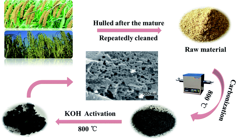
The biomass-based activated carbon derived from GGHs (BSAC) was prepared by a two-step process which included carbonization and chemical activation. Firstly, 2.0 g of pre-prepared ground grain hulls were annealed in the tubular furnace at a slow heating rate of 4 °C min−1 from room temperature to the different temperatures (700, 800, 900 and 1000 °C) under the argon (Ar, 99.99%) atmosphere and held for 2 h. Following activation, the sample were cooled to room temperature under argon flow for later activation treatment. The obtained carbon materials are named as BSAC-n, where n = 700, 800, 900 and 1000.To create the porous structure in carbon matrix, the sample of BSAC-n (0.5 g) was treated with KOH with the mass ratio of 4![[thin space (1/6-em)]](https://www.rsc.org/images/entities/char_2009.gif) :
:![[thin space (1/6-em)]](https://www.rsc.org/images/entities/char_2009.gif) 1 (KOH
1 (KOH![[thin space (1/6-em)]](https://www.rsc.org/images/entities/char_2009.gif) :
:![[thin space (1/6-em)]](https://www.rsc.org/images/entities/char_2009.gif) BSAC-n). Then the mixtures were stirred with 40 mL absolute ethanol at 80 °C for 2 h to form the black paste. After static soaking in room temperature for 24 h, the mixtures were dried at 70 °C in an oven for 48 h. After that, the as-obtained materials were heated at the different temperatures (700, 800, 900 and 1000 °C) under argon atmosphere in the tubular furnace for 2 h. Afterwards, the obtained samples were washed with 3 M HCl and then rinsed with deionized water until the pH of washing effluent reached 6–7. Finally, the activated carbon material can be gained after dried at 80 °C for 8 h. The final activated products were labelled as BSAC-A-n, where n = 700, 800, 900 or 1000. The entire preparation process for the BSAC-A-n is illustrated schematically in Fig. 1.
BSAC-n). Then the mixtures were stirred with 40 mL absolute ethanol at 80 °C for 2 h to form the black paste. After static soaking in room temperature for 24 h, the mixtures were dried at 70 °C in an oven for 48 h. After that, the as-obtained materials were heated at the different temperatures (700, 800, 900 and 1000 °C) under argon atmosphere in the tubular furnace for 2 h. Afterwards, the obtained samples were washed with 3 M HCl and then rinsed with deionized water until the pH of washing effluent reached 6–7. Finally, the activated carbon material can be gained after dried at 80 °C for 8 h. The final activated products were labelled as BSAC-A-n, where n = 700, 800, 900 or 1000. The entire preparation process for the BSAC-A-n is illustrated schematically in Fig. 1.
2.3 Preparation of the BSAC electrode and electrochemical measurements
The SC electrodes were prepared by mixing the as-prepared active material powders (BSAC-A-n), acetylene black and polytetrafluoroethylene emulsion (60%, PTFE) with a weight ratio of 8![[thin space (1/6-em)]](https://www.rsc.org/images/entities/char_2009.gif) :
:![[thin space (1/6-em)]](https://www.rsc.org/images/entities/char_2009.gif) 1
1![[thin space (1/6-em)]](https://www.rsc.org/images/entities/char_2009.gif) :
:![[thin space (1/6-em)]](https://www.rsc.org/images/entities/char_2009.gif) 1. Then, a few drops of deionized water were added to form the thick slurry. Subsequently, the resultant slurry was homogeneously pasted onto a porous Ni foam sheet (1 cm × 1 cm), followed by pressed under a pressure of 10 MPa and dried at 80 °C for 24 h. The 17 m (molality, mol kg−1) NaClO4 electrolyte, was prepared by dissolving NaClO4·H2O salts (23.88 g) in ultrapure water (6.94 g) and the solution was maintained under magnetic stirring for 1 h until the NaClO4 was completely dissolved.
1. Then, a few drops of deionized water were added to form the thick slurry. Subsequently, the resultant slurry was homogeneously pasted onto a porous Ni foam sheet (1 cm × 1 cm), followed by pressed under a pressure of 10 MPa and dried at 80 °C for 24 h. The 17 m (molality, mol kg−1) NaClO4 electrolyte, was prepared by dissolving NaClO4·H2O salts (23.88 g) in ultrapure water (6.94 g) and the solution was maintained under magnetic stirring for 1 h until the NaClO4 was completely dissolved.
It is worth mentioning that the stainless steel electrodes are chosen when using the 17 m (molality, mol kg−1) NaClO4 (17 m is equivalent to 9.2 M (mol L−1)) solution because it will exhibit best electrochemical stability with respect to copper, nickel and titanium. The Ni foam electrodes are chosen for 2 M (mol L−1) KOH aqueous solution (three-electrode measurements) and 1 M Na2SO4 aqueous solution (symmetrical capacitor).
For the three-electrode measurements, the as-prepared BSAC-A-n electrode was directly used as working electrode (WE), a platinum electrode as counter electrode (CE) and a saturated calomel electrode (SCE) as reference electrode (RE). The electrochemical performances were evaluated by cyclic voltammetry, galvanostatic charge–discharge technique and electrochemical impedance spectroscopy using an electrochemical workstation (CHI 760E). All the tests were carried out at room temperature in a 2 M (mol L−1) KOH aqueous solution. According to the three-electrode data, the specific capacitance of the single electrode material can be calculated from the cyclic voltammetry (CV) curves and discharge curves with the eqn (1) and (2), respectively.28
 | (1) |
| Cs = IΔt/mΔV | (2) |
Moreover, symmetrical capacitor was fabricated by assembling the BSAC-A-800 as positive and negative electrode and separated by a porous non-woven cloth in an assembled supercapacitor with the electrode size of 1 × 1 cm. The mass for positive and negative electrode are set as 2.0 and 2.1 mg when using 17 m NaClO4, respectively and the total mass of the active materials 4.1 mg (actual calculation needs to be multiplied by 0.8). When the electrolyte is 1 M Na2SO4, the mass for positive and negative electrode are 2.5 and 2.4 mg and the total mass is 4.9 mg. The specific capacitance is calculated by the two-electrode data following eqn (2), except that m is the total mass (4.1 × 0.8 = 3.28 mg for 17 m NaClO4 and 4.9 × 0.8 = 3.92 mg for 1 M Na2SO4). The energy density (E) in W h kg−1 and power density (P) in W kg−1 derived from galvanostatic charge–discharge curves are calculated from the following expressions:29
 | (3) |
 | (4) |
2.4 Materials characterization
The scanning electron microscopic (SEM) images of the materials were obtained by a field-emission scanning electron microscope (SU8020, HITACHI). Chemical compositions and crystallite structures of the samples were determined by XRD (Rigaku D/max-2550, Japan) using Cu Kα radiation from 10 to 80 angles. The X-ray photoelectron spectra (XPS) were recorded on a VG ESCALAB MK II electron spectrometer. Raman spectra were carried out on a Invia Qontor Raman spectrometer. Nitrogen (N2) adsorption–desorption isotherm measurements were performed on a Micromeritics 3Flex volumetric adsorption analyzer at 77 K. Before adsorption–desorption isotherm measurements, the samples were outgassed at 80 °C for 10 h in the degas port of the analyzer. The specific surface area was calculated by the Brunauer–Emmett–Teller (BET) method.3. Results and discussion
3.1 Structure and morphology characterization of BSAC-n and BSAC-A-n
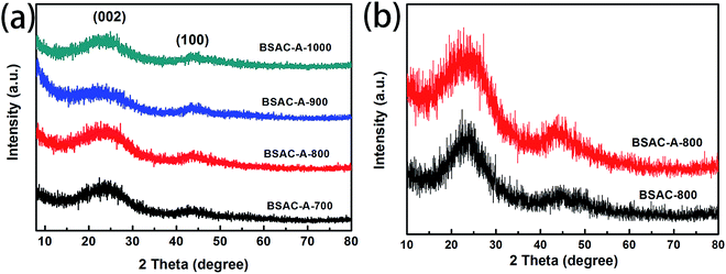
Fig. 2a displays the XRD patterns of the activated carbons derived from different activation temperature of GGHs. Two broad diffraction peaks concentrated at 2θ angle of 22.9° and 43.5°, corresponding to the (002) and (100) planes of carbon, respectively, appear in all samples. The broad peaks of (002) and (100) reflections present the graphitic carbon and the interlayer condensation, respectively. Moreover, no extra peaks can be found in all the samples, demonstrating the carbonization is quietly complete and there are no introduced impurities. Fig. 2b shows the comparative XRD patterns of the BSAC-800 and BSAC-A-800. The (002) diffraction peak intensity of BSAC-A-800 is relatively weak, suggesting the activated with KOH will create more amorphous structure and defects.Fig. 3 describes the SEM images of BSAC-A-n with different carbonization temperature. It can be seen from the low magnification scan that all samples show the presence of open pores structure, forming an irregular bulk structure. The BSAC-A-700 (Fig. 3a1–a3) lacks copious channels and the carbon block exhibits massy and tight, which is not conducive to ion transport. For BSAC-A-1000 (Fig. 3d1–d3), a large number of three-dimensional silk-like nanoflakes are formed on the edges and surfaces of carbon blocks, which means the BSAC-A-1000 possesses a high degree of graphitization and electrical conductivity. In general, the ordered graphitized carbon material is more electrochemically stable, but it frequently results in low surface area and insufficient porosity, which weakens the interactions between materials and electrolyte. The above conclusion is consistent with the BET results. In addition, compared with BSAC-A-700 and BSAC-A-1000, both BSAC-A-800 (Fig. 3b1 and b2) and BSAC-A-900 (Fig. 3c1–c3) have a typical hierarchical porous structure with abundant macropores, mesopores and micropores, which can shorten the ion transport path.30 The multi-pores for BSAC-A-800 (Fig. 3b3) are mainly concentrated in micropores and mesopores and the size is calculated to be ∼5 nm, while the carbon blocks of BSAC-A-900 contain numerous macropores, which is not conducive to providing more active sites. Therefore, carbonization temperature of 800 °C is considered to effectively configure porous structure and store energy.
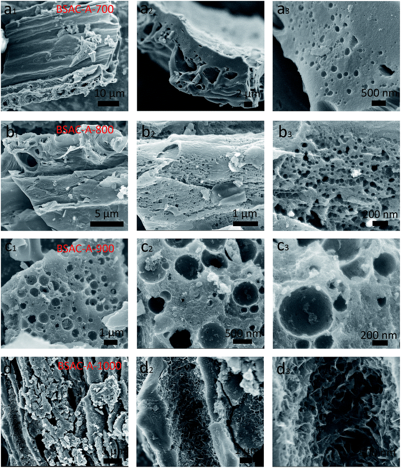 | ||
| Fig. 3 SEM images of (a1–a3) BSAC-A-700, (b1–b3) BSAC-A-800, (c1–c3) BSAC-A-900, (d1–d3) BSAC-A-1000. | ||
Furthermore, Raman spectroscopy (Fig. 4a) is applied to analyze the sample's degree of graphitization. It clearly exhibits that all of curves show two peaks at around 1350 cm−1 and 1590 cm−1, which corresponds to the wavenumbers of D and G bands for carbon materials (for BSAC-A-800, D band at 1352 cm−1 and G band at 1590 cm−1). For BSAC-A-1000, there is also an obvious 2D-band at 2694 cm−1, which is the characteristic band of 3D graphene.31 This is mainly due to that the activation temperature may induce more local stacking and more ordering layer. D and G bands are related to defective sites or disordered sp2 hybridized carbon of graphite and the E2g symmetric vibration of sp2-bonded carbon atoms, respectively.32,33 The intensity ratio of ID/IG is 0.95, 0.99, 0.99 and 0.94 for BSAC-A-700, BSAC-A-800, BSAC-A-900 and BSAC-A-1000, respectively. The calculation results indicate that all GGHs-derived carbon samples exhibit similar degrees of graphitization. As a detailed comparison, BSAC-A-1000 exhibits the least ID/IG, displaying its more ordered structure and higher electrical conductivity, which is consistent with its 2D-band. In addition, with the increasing of activation temperature, the increases first and then decreases of the ID/IG ratio may be attributed to that the low activation temperature (500 °C) is incapable of graphitizing the GGHs and too high activation temperature (1000 °C) would urge the activating agent to destroy the graphitized structure.34
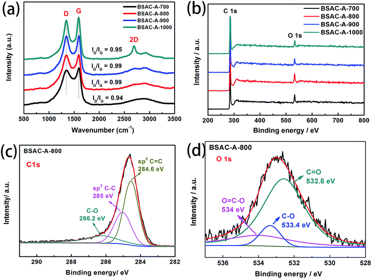 | ||
| Fig. 4 (a) Raman spectra, (b) XPS survey spectrum of as-synthesized BSAC-A-n, (c) C 1 s (d) O 1 s high-resolution spectra of BSAC-A-800. | ||
To further analyze chemical composition and functional groups, the XPS survey spectra of BSAC-A-n are shown in Fig. 4b. It can be observed that the main elements on the surface of all samples are carbon and oxygen. The curve fittings of high-resolution C1s XPS spectra for BSAC-A-800 are performed. As displayed in Fig. 4c and d, three carbon-containing functional groups, namely, sp2 C![[double bond, length as m-dash]](https://www.rsc.org/images/entities/char_e001.gif) C (284.6 eV), sp3 C–C (285 eV), C–O (286.2 eV), can be depicted.35 The O 1 s spectrum is fitted into three peaks, C
C (284.6 eV), sp3 C–C (285 eV), C–O (286.2 eV), can be depicted.35 The O 1 s spectrum is fitted into three peaks, C![[double bond, length as m-dash]](https://www.rsc.org/images/entities/char_e001.gif) O (532.6 eV), C–O (533.4 eV) and O
O (532.6 eV), C–O (533.4 eV) and O![[double bond, length as m-dash]](https://www.rsc.org/images/entities/char_e001.gif) C–O (534 eV). The existence of rich oxygenated functional groups are in favor of BSAC-A-800 to add extra electrochemical capacitance.36
C–O (534 eV). The existence of rich oxygenated functional groups are in favor of BSAC-A-800 to add extra electrochemical capacitance.36
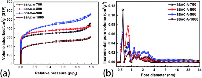
To confirm the pore configurations of BSAC-A-n, N2 sorption isothermals are depicted in Fig. 5a and these corresponding curves of pore size distribution are plotted in Fig. 5b. The specific surface area (SSA) and pore structure parameters of the as-obtained samples are summarised in Table 1. All the adsorption/desorption isotherms (Fig. 5a) exhibit the type I feature with a rapid and analogous increase at P/P0 < 0.05, coupled with obvious hysteresis loops (P/P0 = 0.45–0.95), demonstrating the coexistence of abundant micropores and considerable mesopores in BSAC-A-n.37 In addition, a slight upward tendency at high relative pressure (P/P0 = 0.95–1.0) indicates the existence of macropores. Table 1 shows that GGHs-derived carbon BSAC-A-800 (1376.2 m2 g−1) and BSAC-A-900 possess higher SSA (SBET) than those of BSAC-A-700 and BSAC-A-1000. A large SSA can provide a sufficient electrode–electrolyte interface for the accumulation of charge or ions. Besides, the high activation temperature is conducive to the activation process, while a too high temperature causes the violent gasification reactions, resulting in pore collapse and reducing the SSA.38 As displayed in Fig. 5b, micropore and mesopores are dominant for all samples and they reflect three major peaks at 0.6, 0.8 and 1.2 nm in the micropore region, and one wide and weak peak at 1.8–3.4 nm in the mesopore range. Although BSAC-A-900 has the highest total pore volume (0.87 cm3 g−1) among all of the samples, its micropore volume (0.271 cm3 g−1) and the volume ratio of micropores to total micro-pores (0.31) are lower than those of BSAC-A-800 (0.667 cm3 g−1, 0.417 cm3 g−1, 0.63, respectively). This suggests that BSAC-A-800 possesses a bigger contribution of micropores structure to total pore volume than that of BSAC-A-900 and these micropores serve as more active sites for ion adsorption.31 The high micropore specific surface area are presumed to be responsible for the high specific capacitance of BSAC-A-800. These phenomena appear to correspond to the SEM results.
| Samples | SBET (m2 g−1) | Smic (m2 g−1) | Vt (cm3 g−1) | Vmic (cm3 g−1) | Vmic/Vt |
|---|---|---|---|---|---|
| BSAC-A-700 | 1268.0 | 994.7 | 0.709 | 0.393 | 0.55 |
| BSAC-A-800 | 1376.2 | 1060.4 | 0.667 | 0.417 | 0.63 |
| BSAC-A-900 | 1413.1 | 632.6 | 0.870 | 0.271 | 0.31 |
| BSAC-A-1000 | 797.0 | 396.3 | 0.475 | 0.167 | 0.35 |
3.2 The electrochemical characterizations of BSAC-A-n
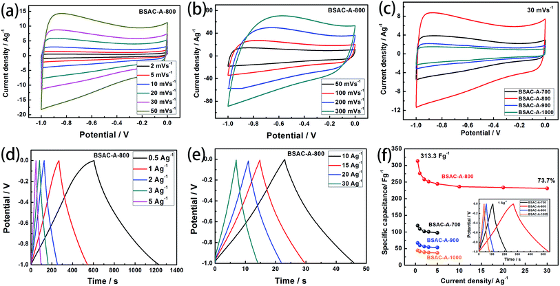
In order to explore the electrochemical properties of the as fabricated BSAC-A-n, cyclic voltammetry (CV) at various scan rates (2–300 mV s−1) in the potential range of −1.0 to 0 V is carried out and the corresponding CV curves are shown in Fig. 6a and b. Apparently, the CV curves of all biomass-drived carbon materials (Fig. 6a, b, S1a, c and e†) exhibit a well symmetrical rectangular shape without any humps, indicating a rapid electrochemical response. Only a little distortion happens at scan rate of 50 mV s−1, it can be attributed to the low inner resistance and fast electrolyte ions diffusion. Subsequently, there is a gradual distortion of CV loop as the scan rate increases from 100 mV s−1 to 300 mV s−1 (Fig. 6b), which is presumably due to the high fraction of micropore, which increases the electrolyte ion transmission resistance at 300 mV s−1.39 In contrast, the CV curves of the four materials are investigated at a scan rate of 30 mV s−1. As presented in Fig. 6c, the area of the CV curve for BSAC-A-800 is much higher than that of BSAC-A-700, BSAC-A-900 and BSAC-A-1000, demonstrating better capacitive properties for BSAC-A-800. The GCD curves of BSAC-A-800 at different current density from 0.5 A g−1 to 30 A g−1 are shown in Fig. 6d and e and GCD curves of the remaining three samples are summarized in Fig. S1b, d and f.† For these carbon materials, all the charge/discharge curves maintain a quasi-triangle shape with nearly equal length of both side, indicating the good capacitive behavior. The specific capacitances (Cs) are calculated from GCD curves according to eqn (2) and the inset image of Fig. 6f gives the GCD curves of the four samples tested at 1 A g−1. The highest specific capacitance of BSAC-A-800 is 313.3 F g−1 at 0.5 A g−1, which is more than twice that of the BSAC-A-700 electrode (119.1 F g−1 at 0.5 A g−1) and much higher in comparison with the BSAC-A-900 (66.7 F g−1 at 0.5 A g−1) and BSAC-A-1000 (44.6 F g−1 at 0.5 A g−1). Moreover, it is important to investigate the capacitance retention at a higher current density and the relationships between Cs value and charge/discharge current density are presented in Fig. 6f. The specific capacitance of BSAC-A-800 decreases to 230.9 F g−1 at 30 A g−1, showing a good rate performance with a retention capability of 73.7%. The result, indication of high power density, probably owing to the suitable size distribution of meso/micropores granting effective accessibility for electrolyte even at a higher speed, makes the material directly suitable for application.40The life span of BSAC-A-800 has also been investigated by GCD measurement at 10 A g−1 for 10![[thin space (1/6-em)]](https://www.rsc.org/images/entities/char_2009.gif) 000 cycles, and the results are exhibited in Fig. 7. The specific capacitance decreases gradually at the initial 1000 cycles, then tends to steady, and the capacitance retention is 99.1% after 10
000 cycles, and the results are exhibited in Fig. 7. The specific capacitance decreases gradually at the initial 1000 cycles, then tends to steady, and the capacitance retention is 99.1% after 10![[thin space (1/6-em)]](https://www.rsc.org/images/entities/char_2009.gif) 000 cycles, meaning superior cycle stability. For detail, the first and the 10
000 cycles, meaning superior cycle stability. For detail, the first and the 10![[thin space (1/6-em)]](https://www.rsc.org/images/entities/char_2009.gif) 000th GCD curves are further provided in the inset of Fig. 7 and there is no obvious change in the shape, confirming the outstanding cycling durability again. The excellence performance may be attributed to the below aspects presumably. First of all, a large BET surface area provides sufficient electrode–electrolyte interface and increase the surface area accessibility for electrolyte ion transport.41 Second, the typical micropore-dominated hierarchical porous structure facilitates the fast diffusion of KOH ions.42 The electrochemical performance of BSAC-A-800 can also exceed those in literature, as shown in Table 2.11,13,15,19,22,38,39,41–45
000th GCD curves are further provided in the inset of Fig. 7 and there is no obvious change in the shape, confirming the outstanding cycling durability again. The excellence performance may be attributed to the below aspects presumably. First of all, a large BET surface area provides sufficient electrode–electrolyte interface and increase the surface area accessibility for electrolyte ion transport.41 Second, the typical micropore-dominated hierarchical porous structure facilitates the fast diffusion of KOH ions.42 The electrochemical performance of BSAC-A-800 can also exceed those in literature, as shown in Table 2.11,13,15,19,22,38,39,41–45
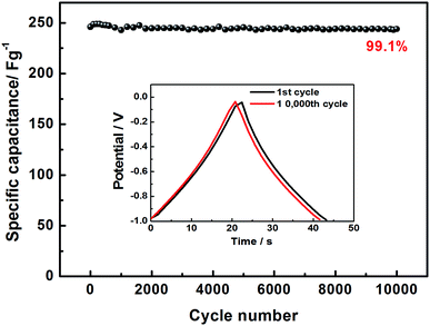 | ||
Fig. 7 Cycling stability of BSAC-A-800 measured at 10 A g−1, the inset is GCD curves of the first, and 10![[thin space (1/6-em)]](https://www.rsc.org/images/entities/char_2009.gif) 000th cycle. 000th cycle. | ||
| Raw material | Electrolyte | Potential range (V) | SBET (m2 g−1) | Cg (F g−1) | Capacitance retention | Ref. |
|---|---|---|---|---|---|---|
| Poplar wood | 2M KOH | −1.0 to 0 | 416 | 234/5 mA cm−2 | 97%/2000 GCD cycles | 11 |
| Pomelo mesocarps | 2M KOH | −1.0 to 0 | 974.6 | 245/0.5 A g−1 | 96.5%/10![[thin space (1/6-em)]](https://www.rsc.org/images/entities/char_2009.gif) 000 GCD cycles 000 GCD cycles |
13 |
| Waste shrimp shells | 6 M KOH | 0 to 1.0 | 1271 | 239/0.5 A g−1 | 99.4%/5000 GCD cycles | 15 |
| Camellia pollen | 2M KOH | −1.1 to 0 | 526 | 205/0.5 A g−1 | 96.2%/10![[thin space (1/6-em)]](https://www.rsc.org/images/entities/char_2009.gif) 000 GCD cycles 000 GCD cycles |
19 |
| Ginkgo leaf | 1M KOH | −1.0 to 0 | 905.9 | 345/0.2 A g−1 | 81%/5000 GCD cycles | 22 |
| Algae | 6 M KOH | −1.0 to 0 | 1538.7 | 287.7/0.2 A g−1 | 98%/8000 GCD cycles | 38 |
| Sheet cellulose | 6 M KOH | −1.0 to 0 | 2045 | 353/1 A g−1 | — | 39 |
| Coal tar pitch and cellulose | 6 M KOH | −1.0 to 0 | 3305 | 308/1 A g−1 | 101.7%/20![[thin space (1/6-em)]](https://www.rsc.org/images/entities/char_2009.gif) 000 CV cycles 000 CV cycles |
41 |
| Waste-cotonier strobili fibers | 6 M KOH | −1.0 to 0 | 2670.8 | 346/1 A g−1 | 84.2%/10![[thin space (1/6-em)]](https://www.rsc.org/images/entities/char_2009.gif) 000 GCD cycles 000 GCD cycles |
42 |
| Pitch | 1 M TEABF4/PC | 0 to 2.5 | 2220 | 157/0.05 A g−1 | 81.5%/8000 GCD cycles | 43 |
| Wheat straw | 3 M KOH | −1.2 to 0 | 2115 | 294/1 A g−1 | 97.6%/5000 GCD cycles | 44 |
| Sugarcane bagasse | 1 M H2SO4 | −0.4 to 0.6 | 2232 | 330/1 A g−1 | 93.6%/10![[thin space (1/6-em)]](https://www.rsc.org/images/entities/char_2009.gif) 000 GCD cycles 000 GCD cycles |
45 |
| GGHs | 2M KOH | −1.0 to 0 | 1038 | 313/0.5 A g−1 | 99.1%/10![[thin space (1/6-em)]](https://www.rsc.org/images/entities/b_char_2009.gif) 000 GCD cycles 000 GCD cycles |
This work |
3.3 The electrochemical characterizations of symmetrical supercapacitors based on BSAC-A-800
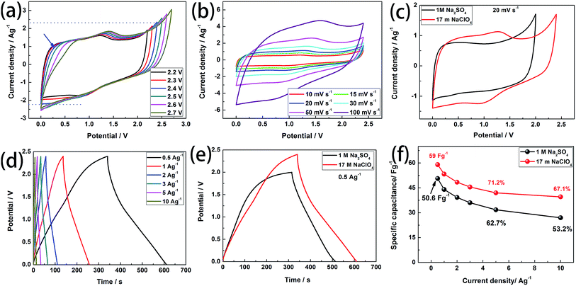
Based on the above conclusions, we further use WIS electrolyte (17 m NaClO4) and salt-in-water electrolyte (SIW, 1 M Na2SO4, ESI†) as the electrolyte in the symmetrical supercapacitors (SSCs) based on BSAC-A-800 to evaluate the practical viability. Similar to the results obtained from the three-electrode system, BSAC-A-800 based on 17 m NaClO4 solution exhibits good electrochemical capacitive behavior. Fig. 8a displays the CV curves of the SSCs based on 17 m NaClO4 recorded at different voltage windows (from 0–2.2 V to 0–2.7 V) with a scan rate of 30 mV s−1, and the voltage windows BSAC-A-800 based on 1 M Na2SO4 is from 0–1.0 V to 0–2.0 V with a scan rate of 50 mV s−1 (Fig. S2a†). At potential window of 0–0.5 V, the oxidation peak continuously bends and approaches the horizontal axis with the increase of the voltage range (marked by blue arrow), which results in a smaller integrated area of CV and a reduction in energy storage. This phenomenon becomes more obvious when the voltage value is greater than 2.4 V. In addition, the ordinate peak of the CV curve with no polarization is almost symmetrical when the voltage window is 0–2.4 V. The above results signify that Ucell = 2.4 V is the optimal voltage range for the energy storage of the symmetrical capacitor. The corresponding test for SSCs based on 1 M Na2SO4 are presented in Fig. S2a.† The obvious polarization peak occurs when the working voltage beyonds 2.0 V and the non-rectangular CV curves can be observed when the voltage is lower than 2.0 V. Thus, the range of 0–2.0 V is chosen for SSCs in 1 M Na2SO4. The CV plots of the SSCs based on 17 m NaClO4 at various scanning rates (10 mV s−1 to 100 mV s−1) are provided in Fig. 8b. A good rectangle-like shape with faint redox characteristic peak can been maintained even the scanning rate up to 100 mV s−1, which reveals the characteristics of the better capacity rate. This result is also found to be similar for SSCs based on 1 M Na2SO4 indicating that both electrolytes can storage energy at approximately the same rate (Fig. S2b†). In addition, the CV plots of the BSAC-A-800 electrode in WIS and SIW electrolyte are recorded at 20 mV s−1 in Fig. 8c. The SSCs based on WIS electrolyte could operate at a higher operating voltage and have a larger integral area than that of the SSCs using 1 M Na2SO4 electrolyte. According to eqn (1), the specific capacity of SSCs using WIS electrolyte is higher than that of SSCs using 1 M Na2SO4 electrolyte.Fig. 8d displays the GCD curves of the SSCs based on 17 m NaClO4 at different current densities (0.5 A g−1 to 10 A g−1). The curves are typical triangular shaped, indicating the ideal EDLCs behavior, consistent with the CV results (Fig. S2c† for SSCs based on 1 M Na2SO4). According to eqn (2), the specific capacitance of SSCs based on 17 m NaClO4 can be calculated to be 59 F g−1 at 0.5 A g−1. This value is higher than that of the SSCs using the 1 M Na2SO4 (50.6 F g−1, Fig. 8e). Even if the current density increases to 10 A g−1, it can also retain 67.1% of the specific capacitance at 0.5 A g−1 (39.6 F g−1), implying an excellent rate capability (53.2%, 26.9 F g−1 for SSCs using 1 M Na2SO4). The rate capabilities are summarised in Fig. 8f and it is also seen that the specific capacitances are gradually decreased with the increase of the current density. The main reason is the electrode material has no enough time to form the electric double layer and proceeds charge adsorption at the higher current density.40
Fig. 9a exhibits the Ragone plots of the SSCs based on BSAC-A-800 using 17 m NaClO4 and 1 M Na2SO4 as the electrolyte. The device using 17 m NaClO4 delivers an energy density of 47.2 W h kg−1 at the power density of 173.7 W kg−1, which is much higher than those of SSCs using 1 M Na2SO4 (28.1 W h kg−1 at 508.9 W kg−1). Moreover, the energy density maintains as 31.8 W h kg−1 with the power density as high as 5109 W kg−1, which is twice the device based on 1 M Na2SO4 (15 W h kg−1 at 14.2 kW kg−1). Notably, the energy and power densities of SSCs based on BSAC-A-800 using 17 m NaClO4 are comparable to or even much better than the previously reported biomass derived carbon-based SSCs.2,4,13,18,41,42,44 In addition, three SSCs in series can easily light 16 LEDs which form the pattern of “○” (see inset of Fig. 8e). The cycle stabilities of SSCs using 17 m NaClO4 and 1 M Na2SO4 are evaluated by repeating the GCD test at 5 A g−1, and an ultrahigh capacitance retention of 98.3% for SSCs using 17 m NaClO4 is achieved after 5000 cycles (as shown in Fig. 9b). This value is slightly higher than that of the SSCs using 1 M Na2SO4 (98.1%). All these experimental results demonstrate that symmetrical supercapacitors using 17 m NaClO4 based on BSAC-A-800 derived from GGHs has great potential prospect in the field of portable and wearable devices.
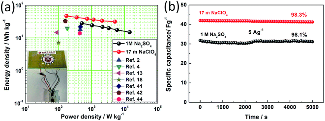 | ||
| Fig. 9 (a) Ragone plot related to energy and power densities of the SSCs using 17 m NaClO4 and 1 M Na2SO4 electrolyte compared with other reported supercapacitors. Inset: lighted “○” LED pattern (Video S1†). (b) Capacitance retention versus cycle number (5 k) for the SSCs using 17 m NaClO4 and 1 M Na2SO4 at a current density of 5 A g−1. | ||
4. Conclusion
In summary, GGHs-derived hierarchical structured carbon with high surface area and large micropore volume is prepared successfully via pre-carbonization and post-activation. Different carbonization/activation temperatures (700, 800, 900 and 1000 °C) have also been studied in detail and the results show that the electrochemical properties of BSAC-A-800 are most prominent. Benefiting from the porous structure and reasonable pore size distribution, the obtained BSAC-A-800 shows an impressive specific capacity of approximately 313.3 F g−1 at 0.5 A g−1 and an excellent cyclic stability with less than 1% degradation after 10![[thin space (1/6-em)]](https://www.rsc.org/images/entities/char_2009.gif) 000 cycles at 10 A g−1. Additionally, the delicate SSCs assembled with BSAC-A-800 using 17 m NaClO4 electrolyte can deliver an integration of excellent properties, such as a high operating voltage of 2.4 V, a high capacitance of 59 F g−1, an outstanding energy density of 47.2 W h kg−1, and a long-term stability of 98.3% retention after 5000 cycles. These results are superior to the SSCs using 1 M Na2SO4. Consequently, our proposed BSAC-A-800 can be fruitfully used for supercapacitor applications and this WIS electrolyte system (17 m NaClO4) could be the most attractive candidate for biomass carbon-based supercapacitors to further improve the energy density.
000 cycles at 10 A g−1. Additionally, the delicate SSCs assembled with BSAC-A-800 using 17 m NaClO4 electrolyte can deliver an integration of excellent properties, such as a high operating voltage of 2.4 V, a high capacitance of 59 F g−1, an outstanding energy density of 47.2 W h kg−1, and a long-term stability of 98.3% retention after 5000 cycles. These results are superior to the SSCs using 1 M Na2SO4. Consequently, our proposed BSAC-A-800 can be fruitfully used for supercapacitor applications and this WIS electrolyte system (17 m NaClO4) could be the most attractive candidate for biomass carbon-based supercapacitors to further improve the energy density.
Conflicts of interest
There are no conflicts to declare.Acknowledgements
This work was supported by the Scientific and Technological Innovation Programs of Higher Education Institutions in Shanxi (201802097), the Doctoral Scientific Research Foundation of Shanxi Datong University (Grant No. 2016-B-14 and No. 2016-B-20), the National Natural Science Foundation of China (51804191), the Shanxi Graphene Industrialization Application Technology of Collaborative Innovation Center, the Shanxi Graphene Functional Materials Engineering Technology Research Center (201705D141034), the Special Talents in Shanxi Province (talents Science and Technology Innovation) (201705D211010), the Key Research Plan (Project) in Industry of Shanxi Province (No. 201703D121037-2), the Datong Applied Basic Research (2017123), and the Shanxi Datong University Training Program of Innovation and Entrepreneurship for Undergraduates (XDC2018122).References
- X. R. Li, X. C. Yang, H. G. Xue, H. Pang and Q. Xu, Metal–organic frameworks as a platform for clean energy applications, EnergyChem, 2020, 2, 100027 CrossRef.
- X. R. Li, X. Xiao, Q. Li, J. L. Wei, H. G. Xue and H. Pang, Metal (M = Co, Ni) phosphate based materials for high-performance supercapacitors, Inorg. Chem. Front., 2018, 5, 11 RSC.
- J. H. Guo, Y. L. Ma, K. Zhao, Y. Wang, B. P. Yang, J. F. Cui and X. B. Yan, High-Performance and Ultra-Stable Aqueous Supercapacitors Based on a Green and Low-Cost Water-In-Salt Electrolyte, ChemElectroChem, 2019, 6, 5433–5438 CrossRef CAS.
- Z. Y. Song, H. Duan, D. Z. Zhu, Y. K. Lv, W. Xiong, T. C. Cao, L. C. Li, M. X. Liu and L. H. Gan, Ternary-doped carbon electrodes for advanced aqueous solid-state supercapacitors based on a “water-in-salt” gel electrolyte, J. Mater. Chem. A, 2019, 7, 15801–15811 RSC.
- S. W. Xu, M. C. Zhang, G. Q. Zhang, J. H. Liu, X. Z. Liu, X. Zhang, D. D. Zhao, C. L. Xu and Y. Q. Zhao, Temperature-dependent performance of carbon-based supercapacitors with water-in-salt electrolyte, J. Power Sources, 2019, 441, 227220 CrossRef CAS.
- Y. Yamada, K. Usui, K. Sodeyama, S. Ko, Y. Tateyama and A. Yamada, Hydrate-melt electrolytes for high-energy-density aqueous batteries, Nat. Energy, 2016, 129, 16129 CrossRef.
- L. M. Suo, O. Borodin, W. Sun, X. L. Fan, C. Y. Yang, K. Xu and C. S. Wang, Advanced High-Voltage Aqueous Lithium-Ion Battery Enabled by “Water-in-Bisalt” Electrolyte, Angew. Chem., Int. Ed., 2016, 55, 7136–7141 CrossRef CAS.
- X. T. Guo, Y. Z. Zhang, F. Zhang, Q. Li, H. Anjum, H. F. Liang, Y. Liu, C. S. Liu, H. N. Alshareef and H. Pang, A novel strategy for the synthesis of highly stable ternary SiOx composites for Li-ion- battery anodes, J. Mater. Chem. A, 2019, 7, 15969–15974 RSC.
- X. D. Bu, L. J. Su, Q. Y. Dou, S. L. Lei and X. B. Yan, A low-cost “water-in-salt” electrolyte for a 2.3 V high-rate carbon-based supercapacitor, J. Mater. Chem. A, 2019, 7, 7541–7547 RSC.
- S. S. Zheng, Q. Li, H. G. Xue, H. Pang and Q. Xu, A highly alkaline-stable metal oxide@metal–organic framework composite for high-performance electrochemical energy storage, Natl. Sci. Rev., 2020, 7, 305–314 CrossRef CAS.
- A. Biswal, P. K. Panda, A. N. Acharya, S. Mohapatra, N. Swain, B. C. Tripathy, Z. T. Jiang and M. M. Sundaram, Role of Additives in Electrochemical Deposition of Ternary Metal Oxide Microspheres for Supercapacitor Applications, ACS Omega, 2020, 5(7), 3405–3417 CrossRef CAS.
- A. Biswal, P. Panda, Z. T. Jiang, B. Tripathy and M. Minakshi, Facile synthesis of a nanoporous sea sponge architecture in a binary metal oxide, Nanoscale Adv., 2019, 1, 1880–1892 RSC.
- N. F. He, S. Yoo, J. J. Meng, O. Yildiz, P. D. Bradford and S. Park, et al., Engineering biorefinery residues from loblolly pine for supercapacitor applications, Carbon, 2017, 120, 304–312 CrossRef CAS.
- J. Ajuria, E. Redondo, M. Arnaiz, R. Mysyk, T. Rojo and E. Goikolea, Lithium and sodium ion capacitors with high energy and power densities based on carbons from recycled olive pits, J. Power Sources, 2017, 359, 17–26 CrossRef CAS.
- M. C. Liu, L. B. Kong, P. Zhang, Y. C. Luo and L. Kang, Porous wood carbon monolith for high-performance supercapacitors, Electrochim. Acta, 2012, 60, 443–448 CrossRef CAS.
- M. Gopiraman, D. Deng, B. S. Kim, I. M. Chung and I. S. Kim, Three-dimensional cheese-like carbon nanoarchitecture with tremendous surface area and pore construction derived from corn as superior electrode materials for supercapacitors, Appl. Surf. Sci., 2017, 409, 52–59 CrossRef CAS.
- H. Peng, G. F. Maa, K. J. Sun, Z. G. Zhang, Q. Yang and Z. Q. Lei, Nitrogen-doped interconnected carbon nanosheets from pomelo mesocarps for high performance supercapacitors, Electrochim. Acta, 2016, 190, 862–871 CrossRef CAS.
- Y. J Cai, Y. Luo, H. W. Dong, X. Zhao, Y. Xiao and Y. Liang, et al., Hierarchically porous carbon nanosheets derived from Moringa oleifera stems as electrode material for high-performance electric double-layer capacitors, J. Power Sources, 2017, 353, 260–269 CrossRef.
- A. K. Mondal, K. Kretschmer, Y. F. Zhao, H. Liu, H. B. Fan and G. X. Wang, Naturally nitrogen doped porous carbon derived from waste shrimp shells for high-performance lithium ion batteries and supercapacitors, Microporous Mesoporous Mater., 2017, 246, 72–80 CrossRef CAS.
- I. I. G. Inal, S. M. Holmes, A. Banford and Z. Aktas, The performance of supercapacitor electrodes developed from chemically activated carbon produced from waste tea, Appl. Surf. Sci., 2015, 357, 696–703 CrossRef CAS.
- F. O. Ochai-Ejeh, A. Bello, J. Dangbegnon, A. A. Khaleed, M. J. Madito and F. Bazegar, et al., High electrochemical performance of hierarchical porous activated carbon derived from lightweight cork, J. Mater. Sci., 2017, 52, 10600–10613 CrossRef CAS.
- X. Y. Li, K. T. Liu, Z. Z. Liu, Z. B. Wang, B. Lia and D. L. Zhang, Hierarchical porous carbon from hazardous waste oily sludge for all-solid-state flexible supercapacitor, Electrochim. Acta, 2017, 240, 43–52 CrossRef CAS.
- C. Lua, Y. H. Huang, Y. J. Wu, J. Li and J. P. Cheng, Camellia pollen-derived carbon for supercapacitor electrode material, J. Power Sources, 2018, 394, 9–16 CrossRef.
- S. Ahmeda, A. Ahmedb and M. Rafat, Impact of aqueous and organic electrolytes on the supercapacitive performance of activated carbon derived from pea skin, Surf. Coat. Technol., 2018, 349, 242–250 CrossRef.
- W. Li Zhang, J. H. Xu, D. X. Hou, J. Yin, D. B. Liu and Y. P. He, et al., Hierarchical porous carbon prepared from biomass through a facile method for supercapacitor applications, J. Colloid Interface Sci., 2018, 530, 338–344 CrossRef.
- S. Yu, X. Q. Zhu, G. B. Lou, Y. T. Wu, K. T. Xu and Y. Zhang, et al., Sustainable hierarchical porous biomass carbons enriched with pyridinic and pyrrolic nitrogen for asymmetric supercapacitor, Mater. Des., 2018, 149, 184–193 CrossRef CAS.
- S. Zhang, C. L. Wu, W. Wu, C. Zhou, Z. W. Xia and Y. Y. Deng, et al., High performance flexible supercapacitors based on porous wood carbon slices derived from Chinese fir wood scraps, J. Power Sources, 2019, 424, 1–7 CrossRef CAS.
- A. Biswal, P. K. Panda, A. N. Acharya, S. Mohapatra, N. Swain, B. C. Tripathy, Z. T. Jiang and M. M. Sundaram, Role of Additives in Electrochemical Deposition of Ternary Metal Oxide Microspheres for Supercapacitor Applications, ACS Omega, 2020, 5, 3405–3417 CrossRef CAS.
- A. Biswal, P. Panda, Z. T. Jiang, B. Tripathybc and M. Minakshi, Facile synthesis of a nanoporous sea sponge architecture in a binary metal oxide, Nanoscale Adv., 2019, 1, 1880–1892 RSC.
- Z. H. Chen, X. W. Peng, X. T. Zhang, S. S. Jing, L. X. Zhong and R. C. Sun, Facile synthesis of cellulose-based carbon with tunable N content for potential supercapacitor application, Carbohydr. Polym., 2017, 170, 107–116 CrossRef CAS.
- S. A. Dong, X. J. He, H. F. Zhang, X. Y. Xie, M. X. Yu and C. Yu, et al., Surface modification of biomass-derived hard carbon by grafting porous carbon nanosheets for high-performance supercapacitors, J. Mater. Chem. A, 2018, 6, 15954–15960 RSC.
- J. Q. Yang, Y. X. Wang, J. L. Luo and L. Y. Chen, Highly nitrogen-doped graphitic carbon fibers from sustainable plant protein for supercapacitor, Ind. Crops Prod., 2018, 121, 226–235 CrossRef CAS.
- W. Yang, W. Yang, L. N. Kong, A. L. Song, X. J. Qin and G. J. Shao, Phosphorus-doped 3D hierarchical porous carbon for high-performance supercapacitors: A balanced strategy for pore structure and chemical composition, Carbon, 2018, 127, 557–567 CrossRef CAS.
- R. Z. Li, J. F. Huang, W. B. Li, J. Y. Li, L. Y. Cao and Z. W. Xu, et al., Controlling carbon-oxygen double bond and pseudographic structure in shaddock peel derived hard carbon for enhanced sodium storage properties, Electrochim. Acta, 2019, 313, 109–115 CrossRef CAS.
- M. Minakshi, M. Barmi, D. R. G. Mitchell, A. J. Barlow and M. Fichtner, Effect of oxidizer in the synthesis of NiO anchored nanostructure nickel molybdate for sodium-ion battery, Materials Today Energy, 2018, 10, 1–14 CrossRef.
- X. Li Su, J. R. Chen, G. P. Zheng, J. H. Yang, X. X. Guan and P. Liu, et al., Three-dimensional porous activated carbon derived from loofah sponge biomass for supercapacitor applications, Appl. Surf. Sci., 2018, 436, 327–336 CrossRef.
- M. Y. Bhat, N. Yadav and S. A. Hashmi, Pinecone-derived porous activated carbon for high performance all-solid-state electrical double layer capacitors fabricated with flexible gel polymer electrolytes, Electrochim. Acta, 2019, 304, 94–108 CrossRef CAS.
- N. Sun, Z. Y. Li, X. Zhang, W. X. Qin, C. J. Zhao and H. M. Zhang, et al., Hierarchical Porous Carbon Materials Derived from Kelp for Superior Capacitive Applications, ACS Sustainable Chem. Eng., 2019, 7, 8735–8743 CrossRef CAS.
- R. J. Mo, Y. Zhao, M. M. Zhao, M. Wu, C. Wang and J. P. Li, et al., Graphene-like porous carbon from sheet cellulose as electrodes for supercapacitors, Chem. Eng. J., 2018, 346, 104–112 CrossRef CAS.
- L. F. Chen, X. D. Zhang, H. W. Liang, M. G. Kong, Q. F. Guan and P. Chen, et al., Synthesis of Nitrogen-Doped Porous Carbon Nanofibers as an Efficient Electrode Material for Supercapacitors, ACS Nano, 2012, 6, 7092–7102 CrossRef CAS.
- B. Qin, Q. Wang, X. H. Zhang, X. L. Xie, L. Jin and Q. Cao, One-pot synthesis of interconnected porous carbon derived from coal tar pitch and cellulose for high-performance supercapacitors, Electrochim. Acta, 2018, 283, 655–663 CrossRef CAS.
- X. L. Su, S. H. Li, S. Jiang, Z. K. Peng, X. X. Guan and X. C. Zheng, Adv. Powder Technol., 2018, 29, 2097–2107 CrossRef CAS.
- K. L. Liu, M. L. Jiao, P. P. Chang, C. Y. Wang and M. M. Chen, Pitch-based porous aerogel composed of carbon onion nanospheres for electric double layer capacitors, Carbon, 2018, 137, 304–312 CrossRef CAS.
- W. M. Du, Z. R. Zhang, L. G. Du, X. Y. Fan, Z. W. Shen and X. R. Ren, et al., Designing synthesis of porous biomass carbon from wheat straw and the functionalizing application in flexible, all-solid-state supercapacitors, J. Alloys Compd., 2019, 797, 1031–1040 CrossRef CAS.
- B. Wang, Y. h. Wang, Y. Y. Peng, X. Wang, N. X. Wang and J. Wang, et al., Nitrogen-doped biomass-based hierarchical porous carbon with large mesoporous volume for application in energy storage, Chem. Eng. J., 2018, 348, 850–859 CrossRef CAS.
Footnote |
| † Electronic supplementary information (ESI) available: Fig. S1: CV curves of (a) BSAC-A-700, (c) BSAC-A-900, (e) BSAC-A-1000 at different scan rate. GCD curves of (b) BSAC-A-700, (d) BSAC-A-900, (f) BSAC-A-1000 at different current density. Fig. S2: (a) CV curves of the symmetric supercapacitor based on BSAC-A-800 using 1 M Na2SO4 measured at different voltage windows (b) CV curves of the SSCs using 1 M Na2SO4 at different scan rates (10–100 mV s−1). (c) GCD curves of the SSCs using 1 M Na2SO4 at various current densities. See DOI: 10.1039/d0ra07448a |
| This journal is © The Royal Society of Chemistry 2020 |

