 Open Access Article
Facile synthesis of ternary flexible silica aerogels with coarsened skeleton for oil–water separation
Yu Zhanga,
Qianqian Shena,
Xuesha Lia,
Hongmei Xieb and
Chaoyin Nie *a
*a
aSchool of Materials and Energy, Southwest University, Chongqing, 400715, China. E-mail: niecy@swu.edu.cn
bCollege of Materials Science and Engineering, Yangtze Normal University, Chongqing, 408100, China
First published on 20th November 2020
Abstract
Ternary flexible silica aerogels were synthesized using a facile sol–gel process without solvent exchange and surface modification using dimethyldiethoxysilane (DEDMS), methyltriethoxysilane (MTES) and tetraethoxysilane (TEOS) via ambient pressure drying. The skeleton morphology of the aerogels was precisely controlled by the DEDMS/TEOS molar ratio (D). The effect of the morphology of the aerogel skeleton on the mechanical properties and the adsorption capacity was investigated. As the D increased, the morphology of the aerogel skeleton gradually changed from a fragment structure to a coarsened structure, and finally to a chain-like structure. The prepared coarsened structure aerogel exhibited a low density of 0.095 g cm−3, a compressible amount reaching up to 78.2%, a Young's modulus as low as 14 kPa, a superhydrophobicity with a contact angle of 154.8° and an excellent adsorption capacity of 8.7–15.4 g g−1. Furthermore, the outstanding recycling ability and corrosion resistance made the aerogels suitable for oil–water separation in corrosive environments.
1. Introduction
Due to the low density, the low thermal conductivity, the excellent hydrophobicity and the unique three-dimensional network structure, silica aerogels have been applied in the fields of light emitting diodes, thermal insulations, acoustic absorptions and catalysis.1–6 However, conventional silica aerogels have poor mechanical properties because they contain too many Si–O–Si bonds, resulting in a rigid skeleton structure.7–9At present, there are two main methods for improving the mechanical properties of silica aerogels. One is to add high polymers with a good flexibility (such as tin dioxide nanofibers or cellulose) to enhance the mechanical properties of aerogels. Zhang10 et al. synthesized tin dioxide nanofibers by electrostatic spinning, and then prepared a SiO2/SnO2 nanofiber composite aerogel using the sol–gel method. As compared with pure silica aerogel, the composite aerogel possessed a smaller volume shrinkage, a better thermal insulation and better mechanical properties. Pirzada11 et al. prepared a multifunctional aerogel with cellulose diacetate (CDA) nano-hybrid fiber and silica treated using the sol–gel method. The compressible strain of the aerogel was as high as 80%, and it exhibited an excellent oil–water separation ability and a good thermal insulation. Although the composite aerogel prepared by this method possessed excellent mechanical properties, the introduction of high polymers significantly increased the density and thermal conductivity.12 The other is to introduce a silicon source containing hydrophobic groups to improve the mechanical properties by adjusting the pore structure of the aerogels. This method is extensively used because of its simplicity, safety and low cost. Wang13 et al. used methyltrimethoxysilane (MTMS) and dodecyltrimethoxysilane (DTMS) as the co-precursors, and by changing the ratio of the co-precursors and the silane concentration, a flexible mesoporous silica aerogel with outstanding hydrophobicity and mechanical properties was prepared. Guo14 et al. synthesized a binary flexible aerogel using dimethyldimethoxysilane (DEDMS) and MTMS. The maximum compression strain of the sample was increased from 10% to 60%, and the elastic modulus was reduced from 1.94 to 0.25 kPa by optimizing the recipe. However, only two Si sources cannot precisely regulate the microstructure of flexible aerogels to achieve the desired properties.
Therefore, an extra Si source containing hydrophobic groups was added based on the dual silicon source system to accurately control the microstructure of the aerogels. Compared with the binary aerogel, the obtained ternary flexible aerogel exhibited a better flexibility (the compressive strain could reach to 80%).15 However, as far as we know, most of the existing reports on the factors affecting the flexibility of aerogels focused on the adjustment of their pores.16,17 The influence of the morphology of the silica skeleton on the flexibility of aerogels has never been explored. In addition, the introduction of a mass of hydrophobic groups reduces the crosslinking of the aerogel skeleton, resulting in a fragile structure.18 Therefore, researchers had to make a crack-free aerogel through a slow condensation reaction (to make the pores of the aerogel more uniform) and a slow drying (to reduce cracking), which greatly increased the sample preparation time (1.5–3 days)15,19 and seriously limited the production efficiency and large-scale applications of flexible silica aerogels.
In this work, we chose DEDMS, MTES and TEOS as the co-precursors, and flexible silica aerogels were synthesized by a simple sol–gel process. The molar ratio of DEDMS/TEOS was used to precisely control the skeleton morphology of the aerogels. This study aimed at investigating the effect of the DEDMS/TEOS molar ratio on the skeleton morphology, the mechanical properties and the adsorption capacity of the aerogels. Flexible aerogels obtained by optimizing the recipe exhibited excellent mechanical properties, hydrophobicity and adsorption capacity, and therefore could be applied in an oil–water separation.
2. Experimental section
2.1. Materials and preparation
Dimethyldiethoxysilane (DEDMS, 97%), methyltriethoxysilane (MTES, 98%) and tetraethoxysilane (TEOS, 98%) were purchased from Shanghai Maclean Biochemical Technology Co., Ltd. Cetyltrimethylammonium bromide (CTAB, 99%) was purchased from Sinopharm Chemical Reagent Co., Ltd. Hydrochloric acid (HCl), ammonia (NH4OH) and ethanol were purchased from Chongqing Chuandong Chemical Co., Ltd.Flexible silica aerogels were obtained by an acid-base two-step catalytic method. Firstly, TEOS, MTES and DEDMS were added in a mixture of ethanol and water dissolved in 0.1 g CTAB and 0.12 M of 1 ml HCl and stirred for 45 min at 40 °C. The molar ratio of MTES![[thin space (1/6-em)]](https://www.rsc.org/images/entities/char_2009.gif) :
:![[thin space (1/6-em)]](https://www.rsc.org/images/entities/char_2009.gif) (DEDMS + TEOS)
(DEDMS + TEOS)![[thin space (1/6-em)]](https://www.rsc.org/images/entities/char_2009.gif) :
:![[thin space (1/6-em)]](https://www.rsc.org/images/entities/char_2009.gif) ethanol
ethanol![[thin space (1/6-em)]](https://www.rsc.org/images/entities/char_2009.gif) :
:![[thin space (1/6-em)]](https://www.rsc.org/images/entities/char_2009.gif) water was 1
water was 1![[thin space (1/6-em)]](https://www.rsc.org/images/entities/char_2009.gif) :
:![[thin space (1/6-em)]](https://www.rsc.org/images/entities/char_2009.gif) 0.23
0.23![[thin space (1/6-em)]](https://www.rsc.org/images/entities/char_2009.gif) :
:![[thin space (1/6-em)]](https://www.rsc.org/images/entities/char_2009.gif) 6.57
6.57![[thin space (1/6-em)]](https://www.rsc.org/images/entities/char_2009.gif) :
:![[thin space (1/6-em)]](https://www.rsc.org/images/entities/char_2009.gif) 14.62. The DEDMS/TEOS molar ratio (D) was used to control the skeleton morphology of the aerogels, which ranged from 0.27 to 0.87. Then, 2.5 M of 4 ml ammonia was dropwise added with vigorous stirring for 2 min and transferred into a mold for gelation. Subsequently, the gel was aged in ethanol at 40 °C for 4 h. The aged gel was cleaned with ethanol for three times. Finally, the alcogel was dried under ambient pressure at 50 °C for 1 h and 70 °C for 2 h to obtain the flexible silica aerogels. The aerogels were prepared with varied DEDMS/TEOS molar ratios (D) of 0.27, 0.47, 0.67, and 0.87 are denoted as D-0.27, D-0.47, D-0.67 and D-0.87, respectively.
14.62. The DEDMS/TEOS molar ratio (D) was used to control the skeleton morphology of the aerogels, which ranged from 0.27 to 0.87. Then, 2.5 M of 4 ml ammonia was dropwise added with vigorous stirring for 2 min and transferred into a mold for gelation. Subsequently, the gel was aged in ethanol at 40 °C for 4 h. The aged gel was cleaned with ethanol for three times. Finally, the alcogel was dried under ambient pressure at 50 °C for 1 h and 70 °C for 2 h to obtain the flexible silica aerogels. The aerogels were prepared with varied DEDMS/TEOS molar ratios (D) of 0.27, 0.47, 0.67, and 0.87 are denoted as D-0.27, D-0.47, D-0.67 and D-0.87, respectively.
2.2. Methods and characterization
The density (ρb) of the flexible aerogels was calculated by their mass (m) and volume (V), and the porosity was calculated by the following formula:
 | (1) |
The original microscopic morphology and damaged morphology of flexible silica aerogels were observed using a field-emission scanning electron microscope (FE-SEM, JSM-7800F, Japan) with an accelerating voltage of 15 kV. The chemical composition of the aerogels was measured using a Fourier transform infrared spectrometer (FTIR, Nicolet 6700, USA), and the spectrum ranged from 400 to 4000 cm−1. The mechanical properties of the aerogels were tested on a universal testing machine (CMT 4503, China) with a loading rate of 2 mm min−1. The Young's moduli were calculated from the linear part (1–5%) of the stress–strain curve. The contact angles of the aerogels were measured on a goniometer (Dataphysics OCA25, Germany) with a water droplet of 5 μl. All contact angles were tested three times and average value was considered as the result.
3. Results and discussion
3.1. Microstructure and physical properties of the flexible aerogels
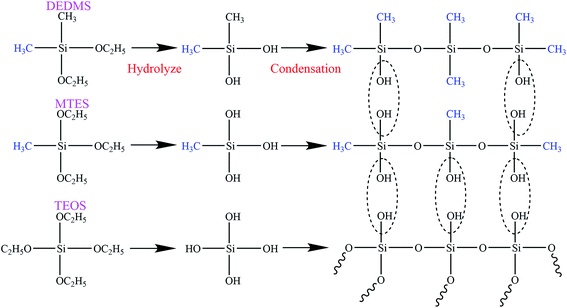
The flexible silica aerogels were prepared by hydrolysis and condensation polymerization as shown in Fig. 1. MTES was used as the silicon source that constituted the main body of the aerogel skeleton. The relative number of the methyl groups and Si–O–Si bonds was changed by adjusting the molar ratio of DEDMS/TEOS to achieve a precise control of the aerogel skeleton morphology.The skeleton morphology of the aerogel was investigated using SEM analysis. Fig. 2 exhibits the SEM images of the flexible aerogels obtained at different molar ratios of DEDMS/TEOS (D). When the D was low, too little DEDMS caused a low phase separation, which facilitated the formation of a dense pore structure and an incomplete aerogel skeleton composed of small silica clusters (Fig. 2a). As the D increased to 0.47, the skeleton became thicker and more complete, and the secondary particles connected more tightly (Fig. 2b). Note that the skeleton surface was relatively rough. The rough surface provided larger contact area for connecting secondary particles, which was in favor of forming a strong framework. With the D further increased, a chain-like structure comprising large smooth spherical particles was observed (Fig. 2c and d). The excessive DEDMS significantly improved the phase separation of the system, resulting in the secondary particles tending to be smooth spheres.20,21 In addition, there were different degrees of necking at the interface between particles, which may had a negative effect on the stability of the structure.
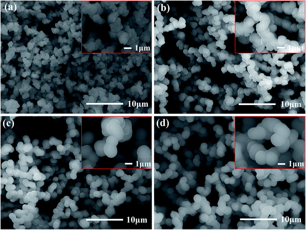 | ||
| Fig. 2 SEM images of the skeleton morphology of the aerogel: (a) D-0.27, (b) D-0.47, (c) D-0.67 and (d) D-0.87. | ||
Photographs of the flexible silica aerogels are shown in Fig. 3. The physical properties of the aerogels with different molar ratio of DEDMS/TEOS are listed in Table 1. With the D increased, the line shrinkage of the flexible aerogels first decreased from 16.4% to 15.1%, and then increased to 28.8%, while the density first decreased from 0.099 g cm−3 to 0.095 g cm−3, and then increased to 0.154 g cm−3 (Table 1). The appropriate methyl groups derived from DEDMS decreased the crosslinking of the aerogel skeleton, which transformed from a rigid structure to a flexible structure. Furthermore, the mutual repulsion of the methyl groups enhanced the spring-back effect of the aerogels during the drying process, so the aerogels could recover to its original size after the solvent was completely evaporated.22 However, excessive DEDMS further weakened the crosslinking of the aerogels, leading to a fragile skeleton with a large line shrinkage and density.
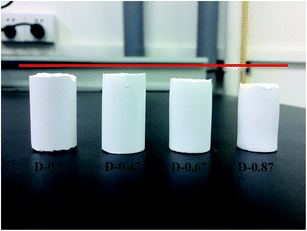 | ||
| Fig. 3 Photographs of the flexible aerogel: D-0.27, D-0.47, D-0.67 and D-0.87, respectively. The red line represents the height of wet gel. | ||
| DEDMS/TEOS | Density (g cm−3) | Line shrinkage (%) | Porosity (%) | Young's modulus (kPa) |
|---|---|---|---|---|
| 0.27 | 0.099 | 16.4 | 95.6 | 45 |
| 0.47 | 0.095 | 15.1 | 95.8 | 14 |
| 0.67 | 0.123 | 19.6 | 94.4 | 17 |
| 0.87 | 0.154 | 28.8 | 93.0 | 20 |
3.2. Mechanical properties of the flexible aerogels
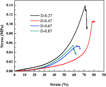
To investigate the effect of the different aerogel skeleton structures on their mechanical properties, uniaxial compression experiments were performed on D-0.27, D-0.47, D-0.67 and D-0.87. The stress–strain curves are shown in Fig. 4, and the corresponding Young's moduli are shown in Table 1. Interestingly, the most widely reported aerogels with a necklace-like structure (D-0.67 and D-0.87) exhibited the lowest maximum compression strain (about 60%), while the aerogels with a rough skeleton structure possessed the highest one (up to 78.2%). In addition, as listed in Table 1, the Young's modulus first decreased and then increased with the increase of D. When the D was 0.47, the aerogel presented the lowest Young's modulus (14 kPa).Fig. 5a–c show the changes of the skeleton structure of the fragmented structure aerogel (D-0.27), the coarsened structure aerogel (D-0.47) and the chain-like structure aerogel (D-0.87) during compression, respectively, which can be used to illustrate the differences in the mechanical properties of the aerogels with different skeleton structures. As for D-0.27, the framework formed by loosely aggregated silica clusters had numerous weak connections, which could become the source of the fracture during the compression process resulting in a damaged structure at a strain of about 70% (Fig. 5a). In addition, a rigid skeleton was formed due to fewer methyl groups, leading to a large Young's modulus (45 kPa). Under the action of an external force, the rigid skeleton was prone to entire brittle fracture (Fig. 4), leading to a sudden failure of the aerogel, which limits the practical applications of the material. However, for D-0.47, the rough surface provided more contact area for the connection of secondary particles. Furthermore, the interlocking between the secondary particles made the skeleton stronger and enhanced the structural stability (Fig. 5b). In addition, more methyl groups allowed the aerogel skeleton to be changed from a rigid structure to a flexible structure, which reduced the degree of crosslinking and provided more space for a compressing network. Therefore, D-0.47 exhibited a compression strain up to 78.2%, and a Young's modulus of as low as 14 kPa. By observing the fracture morphology of D-0.47 (Fig. 5b), it was not difficult to find that the fracture surface distribution was irregular, indicating that the framework had no obvious mechanical weak point. More importantly, even if a part of the flexible skeleton is broken, it will not cause sudden failure of the structure (Fig. 4). However, as D further increased to 0.87, the amount of methyl groups in the system increased significantly. The smooth secondary spherical particles only connected by few Si–O–Si bonds forming a fragile chain-like structure. Eventually, the skeleton of D-0.87 fractured under a low strain, and the fracture surface appeared at the interface between the particles (Fig. 5c).
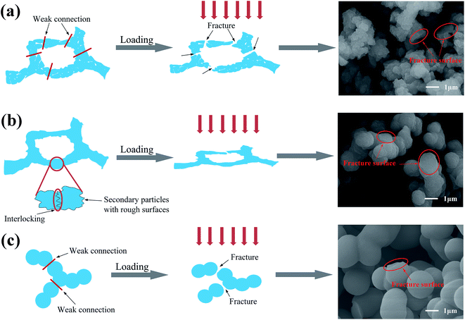 | ||
| Fig. 5 Schematic of the structural change of the aerogel during compression: (a) D-0.27, (b) D-0.47 and (c) D-0.87. | ||
3.3. Hydrophobicity and FTIR analysis of flexible aerogel
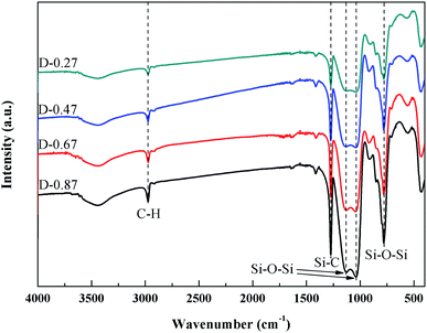
Fig. 6 shows the FTIR spectra of the flexible aerogels under a different DEDMS/TEOS molar ratio. The peaks at 2973 cm−1 were attributed to the vibration of C–H.23 The strong peak at 1272 cm−1 represented the existence of Si–C.24 The broad peaks at 1129, 1035, 777 cm−1 were assigned to the asymmetric and symmetric vibration of Si–O–Si.25 Obviously, as the DEDMS/TEOS molar ratio increased, the intensity of the absorption bond of C–H and Si–C increased, indicating that additional methyl groups were introduced onto the skeleton of the flexible aerogels.Fig. 7a shows the effect of the molar ratio of DEDMS/TEOS (D) on the hydrophobicity of the aerogels. As D increased, the contact angle of aerogels increased sharply first, and then decreased slowly. When D was 0.47, that was the maximum of the contact angle (154.8°). The hydrophobicity of aerogels primarily depended on the surface chemical groups and surface microstructure.26 On the one hand, the increase of hydrophobic groups on the surface of the aerogel skeleton could significantly improve hydrophobicity. On the other hand, the surface of aerogels with micro/nano pore structures could create a certain microscopic roughness, which was beneficial to enhance the hydrophobicity of the aerogels. When the molar ratio of DEDMS/TEOS was too low, fewer methyl groups facilitated the formation of low hydrophobic surface with a contact angle of 139.9°. The hydrophobicity of the aerogels was greatly improved with the increase in D below the appropriate value (0.47). However, an excessive DEDMS led to the formation of huge pores, which were not enough to create a certain surface roughness. Hence, the hydrophobicity of the aerogels decreased.
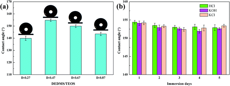 | ||
| Fig. 7 (a) The effect of DEDMS/TEOS molar ratio on contact angles, (b) change of contact angle of the flexible aerogel after immersed to HCl, KOH, KCl solutions. | ||
Furthermore, the corrosion resistance of D-0.47 was also tested. D-0.47 was immersed in HCl (1 M), KOH (1 M) and KCl (1 M) for 5 days, and the contact angle was measured once a day. As shown in Fig. 7b, all contact angles were above 150°, and no obvious variation of the contact angle of D-0.47 was observed, suggesting that the flexible aerogel possessed an outstanding corrosion resistance. It could be attributed to the chemical stability of Si–O–Si and methyl groups.
3.4. Absorption capacity analysis of the flexible aerogels
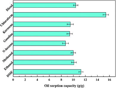
Fig. 8a and b show the process of D-0.47 adsorbing organic pollutants from water. For machine oil (stained with oil red) with lower density than that of water, it was only necessary to move the aerogel floating on the water slightly to complete the adsorption of pollutants (Fig. 8a), leaving transparent and clear water. Likewise, for dichloromethane (dyed with oil red), with higher density than that of water, the aerogel exhibited an excellent absorption capacity (Fig. 8b). This was due to the superhydrophobicity and high porosity of D-0.47. The superhydrophobicity avoided the effect of water on oil–water separation, while the high porosity allowed the aerogel to absorb more organic pollutants. The adsorption capacity of D-0.47 on various organic solvents is shown in Fig. 9. All organic solvents are common pollutants in daily life and industry including diesel, chloroform, kerosene, gasoline, n-hexane, methanol, ethanol and dimethylacetamide. The results showed that D-0.47 exhibited an excellent adsorption capacity with 8.7–15.4 g g−1. As compared to a binary aerogel (6.4–14.8 g g−1)27 and to a single precursor aerogel (2.8–4.7 g g−1),28 D-0.47 possessed a stronger adsorption capacity for organic solvents.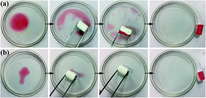 | ||
| Fig. 8 Adsorption process of (a) oil red stained machine oil and (b) oil red stained dichloromethane via using D-0.47. | ||
Recycling capacity is one of the most important properties of aerogels in adsorption. Usually, when an adsorption experiment is completed, the organic liquid in the aerogel is removed by squeezing, and then the next adsorption experiment is carried out.29 However, this approach would make the aerogel structure vulnerable to damage, due to uneven forces affecting recycling ability. Moreover, the organic liquid cannot be completely removed by squeezing, and therefore the recycling ability of the aerogels cannot be accurately characterized. Distillation and vacuum filtration are better methods to remove organic liquids without damaging the skeleton structure of 3D porous materials.13,30,31 Therefore, distillation and vacuum filtration were applied to sufficiently remove the low-boiling and high-boiling organic pollutants in the aerogels, and the recycling ability of the aerogels was accurately characterized. Ethanol and dimethylacetamide were selected as low-boiling point and high-boiling point pollutants, respectively, to test the recycling capacity of D-0.47 and D-0.67. The initial weight of the aerogels was about 0.6 g. The test result is shown in Fig. 10. It can be clearly seen that the absorption capacity of D-0.47 for organic liquids was much higher than that of D-0.67 for both low boiling point and high boiling point pollutants. It was due to D-0.47 possessed a higher porosity (95.8%), which offered more space to store organic solvents. In addition, in the entire cycle test, the absorption capacity of D-0.47 did not fluctuate significantly, and exhibited an excellent cycling stability. This was because the stable skeleton structure without obvious weak connection was not easy to fracture. Therefore, the original three-dimensional network structure could still be maintained during long-term recycling. On the contrary, after 19 times (distillation) and 15 times (vacuum filtration) cycle tests, the adsorption capacity of D-0.67 dropped obviously, which was only 72.3% and 79.2% of the original, respectively. The weak connections at the smooth spherical particle interface were damaged after long-term circulations, resulting in the collapse of the three-dimensional network structure and the reduction of the adsorption capacity.
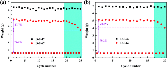 | ||
| Fig. 10 (a) Recycling capacity of the flexible aerogel for ethanol by distillation method, (b) recycling capacity of the flexible aerogel for dimethylacetamide (DMA) by vacuum filtration method. | ||
4. Conclusions
In this paper, using DEDMS, MTES and TEOS as the co-precursors, flexible silica aerogels were rapidly prepared by a simple sol–gel method and an ambient pressure drying. The morphology of the aerogel skeleton was significantly affected by the molar ratio of DEDMS/TEOS. As the molar ratio of DEDMS/TEOS (D) increased from 0.27 to 0.87, the aerogel skeleton changed from a fragment structure to a coarsened structure, and finally to a chain-like structure. As compared to the fragment structure and chain-like structure aerogel, the coarsened structure aerogel obtained in this study exhibited better mechanical properties (the maximum compression was as high as 78.2%, the Young's modulus was as low as 14 kPa) and adsorption capacity (8.7–15.4 g g−1). Besides, the obtained aerogels could be easily recycled for more than 25 times without an obvious decrease of the adsorption capacity. Superhydrophobicity with a contact angle of 154.8° and excellent corrosion resistance enabled the aerogels to be used for oil–water separation in a corrosive environment.Conflicts of interest
There are no conflicts to declare.References
- R. Baetens, B. P. Jelle and A. Gustavsen, Energy Build., 2011, 43, 761–769 CrossRef.
- J. P. Randall, M. A. Meador and S. C. Jana, ACS Appl. Mater. Interfaces, 2011, 3, 613–626 CrossRef CAS.
- E. Cuce, P. M. Cuce, C. J. Wood and S. B. Riffat, Renewable Sustainable Energy Rev., 2014, 34, 273–299 CrossRef CAS.
- T. Tsutsui, M. Yahiro, H. Yokogawa, K. Kawano and M. Yokoyama, Adv. Mater., 2001, 13, 1149–1152 CrossRef CAS.
- G. Wei, Y. Liu, X. Zhang, F. Yu and X. Du, Int. J. Heat Mass Transfer, 2011, 54, 2355–2366 CrossRef CAS.
- S. Zhao, W. J. Malfait, N. Guerrero-Alburquerque, M. M. Koebel and G. Nystrom, Angew. Chem., Int. Ed. Engl., 2018, 57, 7580–7608 CrossRef CAS.
- N. Leventis, C. Sotiriou-Leventis, G. Zhang and A.-M. M. Rawashdeh, Nano Lett., 2002, 2, 957–960 CrossRef CAS.
- G. Zu, T. Shimizu, K. Kanamori, Y. Zhu, A. Maeno, H. Kaji, J. Shen and K. Nakanishi, ACS Nano, 2018, 12, 521–532 CrossRef CAS.
- Z. Wang, D. Wang, Z. Qian, J. Guo, H. Dong, N. Zhao and J. Xu, ACS Appl. Mater. Interfaces, 2015, 7, 2016–2024 CrossRef CAS.
- R. Zhang, Z. An, Y. Zhao, L. Zhang and P. Zhou, Int. J. Appl. Ceram. Technol., 2020, 17, 1531–1539 CrossRef CAS.
- T. Pirzada, Z. Ashrafi, W. Xie and S. A. Khan, Adv. Funct. Mater., 2019, 30, 1907359 CrossRef.
- S. Karamikamkar, H. E. Naguib and C. B. Park, Adv. Colloid Interface Sci., 2020, 276, 102101 CrossRef CAS.
- J. Wang and H. Wang, J. Colloid Interface Sci., 2018, 530, 372–382 CrossRef CAS.
- X. Guo, J. Shan, Z. Lai, W. Lei, R. Ding, Y. Zhang and H. Yang, Molecules, 2018, 23, 945 CrossRef.
- L. Mu, S. Yang, B. Hao and P.-C. Ma, Polym. Chem., 2015, 6, 5869–5875 RSC.
- L.-Z. Zhang and Q.-W. Su, Chem. Eng. Sci., 2018, 192, 61–73 CrossRef CAS.
- J. Ma, F. Ye, S. Lin, B. Zhang, H. Yang, J. Ding, C. Yang and Q. Liu, Ceram. Int., 2017, 43, 5774–5780 CrossRef CAS.
- H. Gao, L. Bo, P. Liu, D. Chen, A. Li, Y. Ou, C. Dong, J. Wang, X. Chen, C. Hou, W. Dong and G. Wang, Sol. Energy Mater. Sol. Cells, 2019, 201, 110122 CrossRef CAS.
- G. Hayase, K. Kanamori and K. Nakanishi, J. Mater. Chem., 2011, 21, 17077 RSC.
- X. Guo, H. Yu, H. Yang, K. Kanamori, Y. Zhu and K. Nakanishi, J. Porous Mater., 2013, 20, 1477–1483 CrossRef CAS.
- X. Guo, W. Li, H. Yang, K. Kanamori, Y. Zhu and K. Nakanishi, J. Sol-Gel Sci. Technol., 2013, 67, 406–413 CrossRef CAS.
- H. Maleki, Chem. Eng. J., 2016, 300, 98–118 CrossRef CAS.
- L. Zhong, X. Chen, H. Song, K. Guo and Z. Hu, New J. Chem., 2015, 39, 7832–7838 RSC.
- H. Yu, X. Liang, J. Wang, M. Wang and S. Yang, Solid State Sci., 2015, 48, 155–162 CrossRef CAS.
- M. L. Perdigoto, R. C. Martins, N. Rocha, M. J. Quina, L. Gando-Ferreira, R. Patricio and L. Duraes, J. Colloid Interface Sci., 2012, 380, 134–140 CrossRef CAS.
- J. Wang, H. Wang and G. Geng, Mar. Pollut. Bull., 2018, 127, 108–116 CrossRef CAS.
- G. Hayase, K. Kanamori, M. Fukuchi, H. Kaji and K. Nakanishi, Angew. Chem., Int. Ed. Engl., 2013, 52, 1986–1989 CrossRef CAS.
- Y. F. Lin and S. H. Hsu, J. Colloid Interface Sci., 2017, 485, 152–158 CrossRef CAS.
- Q. Zhu, Y. Chu, Z. Wang, N. Chen, L. Lin, F. Liu and Q. Pan, J. Mater. Chem. A, 2013, 1, 5386–5393 RSC.
- Y. Liu, K. Zhang, Y. Son, W. Zhang, L. M. Spindler, Z. Han and L. Ren, J. Mater. Chem. A, 2017, 5, 2603–2612 RSC.
- H. Gao, Y. Liu, G. Wang, S. Li, Z. Han and L. Ren, Langmuir, 2019, 35, 4498–4508 CrossRef CAS.
| This journal is © The Royal Society of Chemistry 2020 |

