 Open Access Article
Mobility and versatility of the liquid bismuth promoter in the working iron catalysts for light olefin synthesis from syngas†
Bang
Gu
a,
Deizi V.
Peron
 a,
Alan J.
Barrios
 a,
Mounib
Bahri
b,
Ovidiu
Ersen
 b,
Mykhailo
Vorokhta
 c,
Břetislav
Šmíd
 c,
Dipanjan
Banerjee
de,
Mirella
Virginie
a,
Eric
Marceau
 a,
Robert
Wojcieszak
 a,
Vitaly V.
Ordomsky
 a and
Andrei Y.
Khodakov
 *a
*a
aCNRS, UMR 8181 - UCCS - Unité de Catalyse et Chimie du Solide, Centrale Lille, Univ. Lille, Univ. Artois, F-59000 Lille, France. E-mail: andrei.khodakov@univ-lille.fr
bIPCMS-UMR 7504 CNRS, Université de Strasbourg, 23 rue du Loess, BP 43-67034 Strasbourg Cedex 2, France
cDepartment of Surface and Plasma Science, Faculty of Mathematics and Physics, Charles University, V Holešovičkách 747/2, 180 00 Praha 8, Czechia
dDutch-Belgian Beamline (DUBBLE), European Synchrotron Radiation Facility, 71 Avenue des Martyrs, 38000 Grenoble, France
eDepartment of Chemistry, KU Leuven, Celestijnenlaan 200F Box 2404, 3001 Leuven, Belgium
First published on 27th May 2020
Abstract
Liquid metals are a new emerging and rapidly growing class of materials and can be considered as efficient promoters and active phases for heterogeneous catalysts for sustainable processes. Because of low cost, high selectivity and flexibility, iron-based catalysts are the catalysts of choice for light olefin synthesis via Fischer–Tropsch reaction. Promotion of iron catalysts supported by carbon nanotubes with bismuth, which is liquid under the reaction conditions, results in a several fold increase in the reaction rate and in a much higher light olefin selectivity. In order to elucidate the spectacular enhancement of the catalytic performance, we conducted extensive in-depth characterization of the bismuth-promoted iron catalysts under the reacting gas and reaction temperatures by a combination of cutting-edge in situ techniques: in situ scanning transmission electron microscopy, near-atmospheric pressure X-ray photoelectron spectroscopy and in situ X-ray adsorption near edge structure. In situ scanning transmission electron microscopy conducted under atmospheric pressure of carbon monoxide at the temperature of catalyst activation showed iron sintering proceeding via the particle migration and coalescence mechanism. Catalyst activation in carbon monoxide and in syngas leads to liquid bismuth metallic species, which readily migrate over the catalyst surface with the formation of larger spherical bismuth droplets and iron–bismuth core–shell structures. In the working catalysts, during Fischer–Tropsch synthesis, metallic bismuth located at the interface of iron species undergoes continuous oxidation and reduction cycles, which facilitate carbon monoxide dissociation and result in the substantial increase in the reaction rate.
Introduction
Liquid metals and metal alloys are a new emerging and rapidly growing class of materials,1,2 which have already found numerous applications in different fields including flexible electrodes, biosensors, printable conductors, responsive materials, electronics and microfluidics. Use of liquid metals in heterogeneous catalysis is a genuinely new research field. These elements have a number of attractive characteristics for catalytic applications such as low melting point, high mobility, easy recovery and surface energy. Thus, liquid metals can be considered as a new type of the mobile promoters and active phases for heterogeneous catalysts. The mobility of active phase and promoters during the reaction in heterogeneous catalysts and influence of this mobility on the catalytic performance have been only very rarely considered in the literature. Previous reports have demonstrated that rhodium, gallium and liquid mixture of gallium and palladium exhibit a high selectivity and are very active in selective dehydrogenation of alkanes.3–5 An alloy between nickel and bismuth showed high methane conversion to hydrogen. In this alloy system, the insoluble carbon floats to the surface, where it can be skimmed off.6 Other reports7–9 have addressed migration of alkali ions over the surface of heterogeneous catalysts in the presence of water.The growing demand for light olefins in the context of depletion of oil reserves has stimulated development of alternative olefin manufacturing processes.10,11 Iron-based catalysts are the catalysts of choice for light olefin synthesis via Fischer–Tropsch (FT) synthesis,11–15 because of low cost, high selectivity and flexibility relative to the use of syngas with different H2/CO ratios. Light olefin synthesis from syngas occurs on iron carbide nanoparticles, which form from iron oxides during the catalyst activation.
Recently, we discovered16–19 strong promoting effects of Bi and Pb on the catalytic performance of iron FT catalysts. The reaction rates increased 5–10 times, while the selectivity to light olefins was enhanced by 50%. We have been particularly interested in the bismuth promoter, because of its lower toxicity. The melting point of metallic bismuth is 271 °C. Bismuth can be therefore, liquid at the FT reaction temperature. In addition, bismuth may have several oxidation states, which can evolve during the reaction.
Presumable high mobility of the liquid promoter and versatility of iron catalysts under the conditions of catalyst activation and reaction are the reasons, why these catalysts require in situ techniques operating at higher temperatures. Indeed, only in situ characterization conducted at the reaction temperature and in the presence of reacting gas can overcome major impediments of the ex situ techniques, which operate only in air at ambient conditions, and can provide reliable information about the catalyst active phase, localization of the liquid promoters, active sites and reaction mechanism.
X-ray absorption is a powerful technique to follow electronic structure and coordination of elements in heterogeneous catalysts even at high dilution during the catalyst pretreatment and catalytic reactions.20–24 The in situ X-ray absorption experiments can be conducted at higher temperatures and pressures of several bars with simultaneous analysis of reaction products. Recently developed cutting-edge environmental TEM technique is a unique opportunity for the investigation of catalysts with a high spatial resolution down to the atomic level. Over the last years, a few new high pressure/temperature environmental cells for TEM have been elaborated. They allow in situ observations at pressures up to 1 atm and in the high temperatures range, up to 1000 °C.25,26 Despite its great potential, high pressure environmental TEM has been mostly applied to the study of rather traditional catalytic systems, such as Pt/SiO2 catalysts.27,28
Catalysis is a surface phenomenon. Due to the metastable nature of the catalyst surface in particular, during the catalyst activation and under the reaction conditions, the information about the catalyst surface gained from ex situ studies cannot be reliable. Indeed, the catalyst surface is more susceptible to evolve in presence of gas and higher temperatures than the catalyst volume. Near atmospheric pressure X-ray photoelectron spectroscopy (NAP-XPS)29–31 has capacities of studying the surface of a catalyst under semi- or pseudo-catalytic conditions at the gas pressures of several millibars at higher temperatures.
In order to elucidate the phenomena responsible for the spectacular enhancement of the performance of iron catalysts supported over carbon nanotubes (CNT) after their promotion with bismuth, we uncover and investigate in this paper, the versatility and mobility of bismuth, which is liquid under the reaction conditions. The unique combination of three complementary techniques (in situ XANES, in situ STEM and surface-sensitive NAP-XPS) has allowed a comprehensive picture of the evolution of the FT catalysts under the catalyst activation and operating conditions of FT synthesis to be developed. The continuous migration and redox cycles of the bismuth liquid promoter observed in situ have provided clear interpretation of the sharply enhanced catalytic performance of the bismuth-promoted iron catalysts in high temperature FT synthesis.
Results and discussion
In situ STEM observation of catalyst evolution
The monometallic Fe/CNT iron catalyst and iron catalysts supported by CNT and promoted with bismuth were prepared by either co-impregnation (FeBi/CNT) or mechanical mixing (Fe/CNT + Bi/CNT). The catalyst preparation and conventional characterization are available in ESI.† The iron catalysts were activated in a flow of pure CO at 350 °C. The activation procedure for iron FT catalysts was optimized in our previous report.32First, we investigated the influence of the temperature, activation and reaction gas on the structure of iron catalysts promoted with Bi using in situ environmental STEM. In order to identify the morphology of the bismuth and iron species, we measured first the ex situ STEM images of freshly calcined monometallic Fe/CNT and Bi/CNT samples. The relevant images (Fig. S1, ESI†) show the presence of bismuth oxide and iron oxide nanoparticles located both on the outer surface and inside the CNT. Indeed, the CNT was pre-treated with concentrated HNO3 at 140 °C for 14 h. Previous reports18,33 suggest that the pretreatment with nitric acid can result in the opening of CNT. Consequently, some of the metal nanoparticles can be located outside, but also inside the CNT in the impregnated samples. Interestingly, the STEM images display bismuth oxide nanoparticles smaller than 3–5 nm in Bi/CNT, while the iron oxide nanoparticles are much larger (5–20 nm) in Fe/CNT.
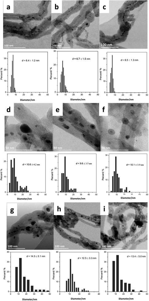
Then, we analyzed by STEM the FeBi/CNT iron catalyst promoted with bismuth and prepared by impregnation (Fig. 1). Metal nanoparticles with the sizes from 3 to 15 nm were detected in the freshly calcined catalyst. The histograms of metal particle size distributions measured from ex situ STEM data in the fresh monometallic Fe/CNT, FeBi/CNT prepared by impregnation and in Fe/CNT + Bi/CNT prepared by mechanical mixing are shown in Fig. 1a–c. The average iron oxide particles size was about 6 nm in all the calcined samples and was not affected by the catalyst preparation method.
The Fe/CNT, FeBi/CNT and Fe/CNT + Bi/CNT catalysts were exposed afterwards to temperature and carbon monoxide both in situ in the STEM cell and ex situ in the conventional catalytic reactor. The temperature procedure is displayed in Fig. S2, ESI.† The catalyst was first exposed to argon at 200 °C, then the temperature was increased in CO to 350 °C and kept at this temperature for a few hours. The whole in situ STEM experiment was conducted under atmospheric pressure. The in situ STEM images of the Fe/CNT + Bi/CNT and FeBi/CNT samples acquired in both bright and dark fields during the catalyst activation in CO are shown respectively in Fig. 2, 3, S3 and S4, ESI.† They clearly show sintering of iron carbide nanoparticles during the exposure to CO at 350 °C in both FeBi/CNT and Fe/CNT + Bi/CNT prepared respectively by co-impregnation and mechanical mixing.
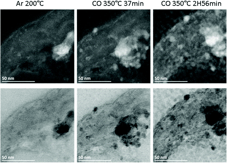 | ||
| Fig. 2 In situ high-angle annular dark field (HAADF, top) and bright field (BF, bottom) STEM images of the Fe/CNT + Bi/CNT sample acquired in different atmospheres and temperatures according to the procedure displayed in Fig. S2.† | ||
Fig. 1d–f, 3 and Fig. S3–S6, ESI† display STEM images and histograms of iron nanoparticles sizes calculated from the ex situ and in situ STEM images of Fe/CNT, FeBi/CNT and Fe/CNT + Bi/CNT during and after the activation in CO. Important, similar particle size distributions were obtained from both the in situ and ex situ STEM data. The catalyst activation in CO in the in situ STEM cell is relevant therefore, to the catalyst pretreatment in the conventional fixed bed reactor. Note that the in situ catalyst characterization by STEM has provided quantitative information about the variation of iron particle sizes during the activation in CO as a function of time. The variation of iron carbide particle size calculated from the in situ TEM images of FeBi/CNT and Fe/CNT + Bi/CNT as a function of time is displayed in Fig. 4. The most significant increase in the carbide particle size was observed already after 30 min of the activation, while further exposure to CO leads to the stabilization of the size of iron carbide nanoparticles at around 9–10 nm. The in situ STEM images clearly demonstrate a progressive sintering of iron nanoparticles during the catalyst activation in CO.
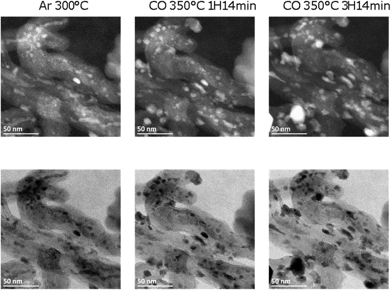 | ||
| Fig. 3 In situ HAADF (top) and BF (bottom) STEM images of a typical area of FeBi/CNT measured in argon and CO at high temperature (P = 1 bar). | ||
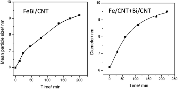 | ||
| Fig. 4 Variation of iron carbide particle size calculated from the in situ STEM data as a function of activation time in CO for FeBi/CNT and Fe/CNT + Bi/CNT catalysts. | ||
We also conducted an evaluation of iron dispersion in the catalysts after conducting FT reaction. The ex situ TEM images and calculated histograms of iron nanoparticle size (Fig. 1g–i) show a further increase in iron nanoparticle size after FT reaction from 9–10 nm in the samples activated in CO to about 12–14 nm in the spent counterparts after FT reaction. No noticeable influence of the promotion with Bi or catalyst preparation method was observed on the iron nanoparticle size in the spent catalysts.
Sintering behavior of supported catalysts could be represented using general power law expression (GPLE) for a wide range of supported metallic catalysts.34,35
Nanoparticle sintering in heterogeneous catalysts may usually occur via two mass-transfer mechanisms:35–37 (a) atomic migration (Ostwald ripening), (b) particle migration and coalescence (PMC). Sintering according to the Ostwald ripening results in the Lifshitz–Slyozov–Wagner asymmetric particle size distribution36–38 skewed to the smaller particle sizes.39 Nanoparticle sintering by PMC typically results in rather symmetric log-normal distribution.35,37 The shape of particle size distribution curves can provide therefore, information about the sintering mechanism, which operates during the catalyst activation or catalytic reaction. The particle distribution histograms calculated from ex situ and in situ STEM data (Fig. 1, Fig. S5 and S6, ESI†) for the activated and spent catalysts exhibit symmetric shape, which could be an argument in favor of higher contribution of PMC to the iron sintering mechanism in FT catalysts.
In GPLE, for most of catalysts, the sintering order is 2, and it is independent of the operating parameters. A sintering order of 2 suggests particle migration and coalescence as the main process for the sintering.40 The measured second order (Fig. S7, ESI†) could be indicative of the PMC mechanism for the sintering of iron catalysts.
Catalytic performance and bismuth redox cycles
In order to better understand the phenomena occurring with iron and bismuth species at the conditions of catalyst activation and FT synthesis, we simultaneously conducted evaluation of catalytic performance and in situ investigation of catalyst structure using XANES. The temperature procedure used for in situ XANES was similar to that in the in situ STEM experiments (Fig. S2, ESI†).The experimental X-ray absorption capillary setup at the ESRF synchrotron (BM26A, DUBBLE beam line) is shown in Fig. S8, ESI.† The catalytic data obtained during the in situ XANES measurements either at 10 bar or at atmospheric pressure of syngas are presented in Table 1. Methane, light olefins, light paraffins and higher C5+ hydrocarbons were among the reaction products. Significant amounts of carbon dioxide were also produced. Water gas shift reaction (CO + H2O = CO2 + H2), which is readily catalyzed by iron catalysts, is one of the reasons of carbon dioxide production. Higher selectivity to CO2 has been observed over the Bi-promoted catalysts compared to the monometallic Fe/CNT counterpart. The promotion of iron catalyst with Bi results in an important increase in the carbon monoxide conversion and iron time yield (FTY). Note that the increase in FT reaction rate on the bismuth promotion differs at 10 bar and atmospheric pressure. On the one hand, the enhancement of FT reaction rate on the Bi-promotion is more significant at atmospheric pressure than at 10 bar. On the other hand for both the promoted and unpromoted catalysts, higher pressure (10 bar) results in much higher reaction rate.
| Catalyst | P, bar | FTY, 10−4 molCO gFe−1 s−1 | CO conv. (%) | CO2 select (%) | Hydrocarbon selectivity (%) | C2–4=/C2–40 | |||
|---|---|---|---|---|---|---|---|---|---|
| CH4 | C2–4= | C2–40 | C5+ | ||||||
| a Reduction: CO flow (5 ml min−1), 350 °C 2 h. Reaction condition: H2/CO = 1/1, 350 °C, P = 10 bar, time = 5 h, GHSV = 4.8 L g−1 h−1. | |||||||||
| Fe/CNT | 10 | 1.21 | 46.3 | 38.2 | 31.8 | 30.3 | 7 | 20.9 | 1.78 |
| 1 | 0.10 | 3.9 | 12.7 | 33.9 | 40.3 | 14 | 11.8 | 2.88 | |
| FeBi/CNT | 10 | 1.71 | 65.7 | 47.9 | 29.1 | 35.3 | 15.9 | 19.7 | 2.22 |
| 1 | 0.56 | 21.4 | 40.7 | 30.8 | 55.4 | 10.1 | 3.7 | 5.49 | |
| Fe/CNT + Bi/CNT | 10 | 1.44 | 55.3 | 45.2 | 30.4 | 33.9 | 15.9 | 20.0 | 2.13 |
| 1 | 0.32 | 12.3 | 36 | 32.0 | 49.6 | 13.1 | 5.3 | 3.79 | |
The bismuth promotion also increases the selectivity to light olefins and decreases the selectivity to light paraffins and to the C5+ hydrocarbons. The Bi promoted iron catalysts present much more noticeable improvement in the reaction rate than other traditional promoters (Na, K). The results are summarized in Table S2, ESI.† Note that a higher FT reaction rate was observed on the Fe/CNT + Bi/CNT catalyst prepared by mechanical mixing compared with the monometallic Fe/CNT counterpart. The effect of the bismuth promotion on the FT reaction rate and olefin selectivity is however, much more significant in the FeBi/CNT catalyst prepared by co-impregnation compared to the mechanical mixture of Fe/CNT and Bi/CNT (Fe/CNT + Bi/CNT). The CO conversion is slightly higher in the in situ XAS cell compared with the conventional fixed-bed reactor (Table S2, ESI†), however the selectivity to light olefins is somewhat lower. The catalytic performance of the monometallic and Bi-promoted catalysts in the in situ capillary cell (Table 1) was consistent with our previous results.16,18 This confirms relevance of the catalytic data obtained in the in situ synchrotron-based capillary setup compared to the conventional laboratory fixed bed reactor. Interestingly, no Bi evaporation occurred during FT reaction. The ICP analysis shows that the catalyst had the same Bi content before and after the reaction (Table S1, ESI†).
Since the promotion with Bi results in the major enhancement of the catalytic performance of iron catalysts, our particular attention was paid to the evolution of the promoter and more particularly, the Bi L3-absorption edge during the catalyst activation and FT reaction. Because of a lower content in the catalyst (<1 wt%), the coordination and electronic state of the Bi promoter are more difficult to follow compared to iron. The XANES spectra at the Bi L3-absorption edge (Fig. S9, ESI†) measured in situ during catalyst activation in pure CO or syngas showed gradual reduction of Bi2O3 to metallic Bi in both co-impregnated and mechanically mixed catalysts. The bismuth phase composition in the FeBi/CNT and Fe/CNT + Bi/CNT catalysts evaluated using linear decomposition of in situ XANES spectra of reference Bi2O3 and metallic Bi during their exposure to carbon monoxide and syngas as a function of temperature is displayed in Fig. S10, ESI† and Table 2.
| Catalysts | Fresh (%) | CO activation 350 °C (%) | Cooling under CO to RT (%) | Reaction in syngas 350 °C (%) | Cooling under syngas to RT (%) | ||||
|---|---|---|---|---|---|---|---|---|---|
| Bi2O3 | Bi2O3 | Bi | Bi2O3 | Bi | Bi2O3 | Bi | Bi2O3 | Bi | |
| FeBi/CNT | 100.0 | 0 | 100.0 | 64.2 | 35.8 | 0 | 100.0 | 6.4 | 93.6 |
| Fe/CNT + Bi/CNT | 100.0 | 0 | 100.0 | 4.1 | 95.9 | 0 | 100.0 | 3.6 | 96.4 |
Interestingly, the catalyst preparation method (co-impregnation versus mechanical mixing) does not affect the temperature of Bi reduction, which occurs in both the FeBi/CNT and Fe/CNT + Bi/CNT catalysts between 150 and 350 °C and is completely achieved at 350 °C for both specimens. Thus, in situ XANES suggests that bismuth reduction during the catalyst activation in pure CO or syngas is not significantly affected by the interaction with iron species. Indeed, bismuth reduction proceeds similarly in the FeBi/CNT and Fe/CNT + Bi/CNT catalysts prepared by co-impregnation and mechanical mixing. Bismuth remains in the metallic state after these two pretreatments in both FeBi/CNT and Fe/CNT + Bi/CNT.
Surprisingly, cooling down activated FeBi/CNT in carbon monoxide (Table 2, Fig. 5 and 6) results in partial re-oxidation of the bismuth species. The fraction of Bi3+ in the FeBi/CNT catalyst increased from 0 to 64% of the total amount of Bi after cooling down in CO. Note that re-oxidization of bismuth species does not occur under the same conditions in the activated Fe/CNT + Bi/CNT catalyst prepared by mechanical mixing. Further investigation showed that bismuth re-oxidation in the activated FeBi/CNT catalyst during cooling depended on the gas atmosphere (Fig. 6). The most significant re-oxidation of bismuth was observed under cooling down the activated catalyst in pure CO. The effect was less important, when the activated FeBi/CNT catalyst was cooled down in syngas. No bismuth re-oxidation was observed during cooling the activated FeBi/CNT catalyst in hydrogen or pure nitrogen (Fig. 6). Subsequent heating of the FeBi/CNT catalyst with partially oxidized bismuth species in CO resulted in reduction of oxidized bismuth to the metallic state.
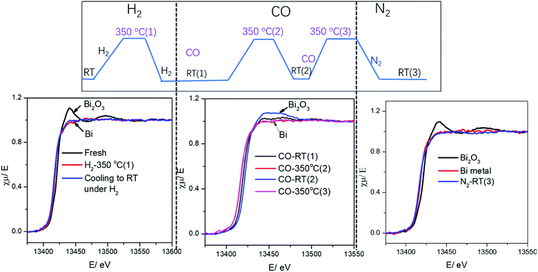 | ||
| Fig. 5 Bi L3-absorption edge XANES in the FeBi/CNT catalyst during activation and cooling to RT under different gas. | ||
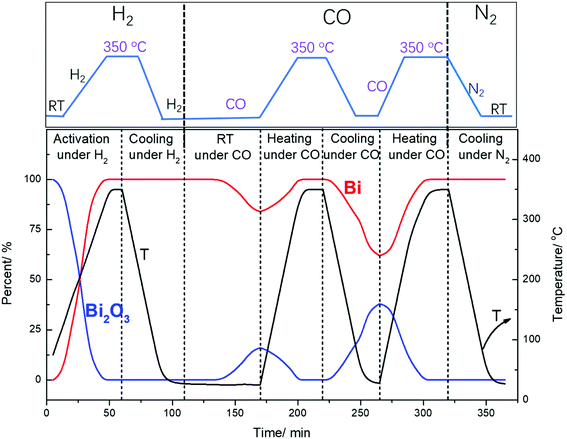 | ||
| Fig. 6 Bismuth phase evolution calculated from XANES in the FeBi/CNT catalyst prepared by co-impregnation during activation and cooling to RT under different gas. | ||
It is important to emphasize that no visible re-oxidation of bismuth in CO at ambient temperature was observed, when the Fe/CNT + Bi/CNT catalyst prepared by mechanical mixing was activated in CO for a relatively short time (∼1 h) (Fig. 7). When the Fe/CNT + Bi/CNT catalyst was activated in carbon monoxide for a longer time (4 h), bismuth re-oxidation was observed after cooling down and exposure to CO at ambient temperature. This could be indicative of the modifications of the structure of the Fe/CNT + Bi/CNT catalyst during its extended heating in CO. These modifications could be due to the migration of liquid bismuth species. The bismuth migration during catalyst activation and FT reaction is discussed below in the manuscript.
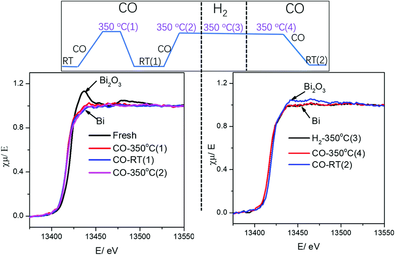 | ||
| Fig. 7 Bi L3-absorption edge XANES in the Fe/CNT + Bi/CNT mixture catalyst during activation and cooling to RT under different gas. | ||
The in situ evolution of XANES spectra at the iron K absorption edge of iron catalysts supported on CNT during their activation and catalytic reaction was studied in our previous publication.18 During the carbidization in CO, supported Fe2O3 phase in the calcined iron catalysts is first converted to Fe3O4 and then to FexCy. The carbidization of Fe3O4 to FexCy is facilitated in the presence of Bi. Easy carbidization of iron agrees with better iron reducibility in the Bi-promoted catalyst.16,18 Iron remains in the form of iron carbide under the flow of syngas at the conditions of FT synthesis. No visible iron re-oxidation or formation of detectible amounts of metallic iron were observed at a wide ranges of conditions used for FT synthesis at 350 °C.18
One of the initial steps of FT synthesis on iron catalysts is carbon monoxide direct or assisted dissociative adsorption.41,42 Carbon monoxide dissociation results in formation of surface carbide and oxygen species (Fig. 8). The adsorbed oxygen can be removed via its reaction with either hydrogen or carbon monoxide producing respectively water or carbon dioxide. The surface carbide can be then hydrogenated to the CHx monomer, which then can initiate or be involved in the FT surface polymerization.43 The in situ XANES data measured during cooling the activated catalyst in the presence of CO show that CO dissociation over Bi-promoted at ambient temperature involves oxygen scavenging by metallic bismuth. The oxygen scavenging results in the formation of oxidized bismuth species detected by in situ XANES. Subsequent treatment of the catalysts with CO leads to the removal of oxygen atoms from bismuth oxidized species with formation of CO2 (Fig. 8). At the same time, bismuth is reduced again to the metallic state. As expected, oxygen scavenging and oxygen transfer to bismuth can only take place when Bi is located in the close proximity to iron carbide. This situation occurs in the FeBi/CNT sample prepared by co-impregnation, while no oxidation was observed in the Fe/CNT + Bi/CNT catalyst prepared by mixing, which was activated for a relatively short time (∼1 h). Iron and bismuth species are spatially separated in this mechanically mixed catalyst. The in situ XANES results are consistent with our previous transient and isotope-tracing experiments,17 showing that the Bi promoter can enhance the CO dissociation.
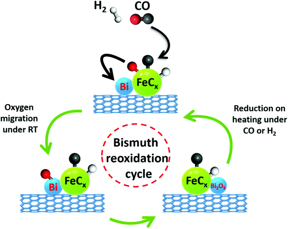 | ||
| Fig. 8 CO dissociation over iron carbide nanoparticles promoted with bismuth and bismuth reoxidation cycle. | ||
The ex situ STEM-EDX characterization of the activated and passivated FeBi/CNT catalyst prepared by co-impregnation showed formation of iron carbide–bismuth core–shell structures16 with Bi atoms located in the shell and iron in the core (Fig. S11, ESI†), while, because of a well-defined spatial separation of iron and bismuth phases, no apparent core–shell structures were observed in the Fe/CNT + Bi/CNT catalyst prepared by mechanical mixture.
Bismuth reduction results in formation of liquid metallic bismuth, which can diffuse over the catalyst surface. Longer exposure of the Fe/CNT + Bi/CNT catalysts with liquid bismuth species to 350 °C leads therefore to the Bi migration and interaction of bismuth with iron carbide species. That was the reason, why the Bi re-oxidation during cooling down in CO was observed in the Fe/CNT + Bi/CNT catalysts activated for a longer time in CO at 350 °C.
Evolution of surface and sub-surface layer in the promoted iron catalysts during activation in CO and in syngas
The surface of the catalyst usually is more sensitive to the conditions of catalyst activation and catalytic reaction than the catalyst bulk structure. Information about evolution of the surface and sub-surface layer in the monometallic and bismuth promoted catalysts in CO or syngas at the activation and reaction temperatures was extracted from the NAP-XPS data. The experimental procedure (temperature, gas) used for NAP-XPS experiments is displayed in Fig. S12, ESI.† The freshly calcined samples were first loaded into the NAP-XPS spectrometer and exposed to CO at 50 °C. Then, the temperature was increased subsequently from room to 250 °C and to 350 °C. After the exposure to 350 °C in CO, the sample was cooled down to 50 °C. After the subsequent temperature increase to 350 °C, CO was switched to syngas (H2/CO = 1) at 350 °C. The sample was maintained in syngas at this temperature and then cooled back again to 50 °C. At different steps of the in situ catalyst treatment under about 1 mbar of CO or syngas, the position, shape and intensity of Fe 2p, C 1s and Bi 4f peaks were thoroughly analyzed by XPS.The Fe 2p NAP-XPS spectra of the FeBi/CNT and Fe/CNT + Bi/CNT catalysts are presented in Fig. 9. The spectra of the calcined catalysts exhibit the Fe 2p peaks at ∼711.2 eV (Fe 2p3/2) and ∼724.6 eV (Fe 2p1/2) with a shakeup satellite peak at ∼719.2 eV. The spectra and binding energies distinctly indicate the presence of Fe3+ species.44
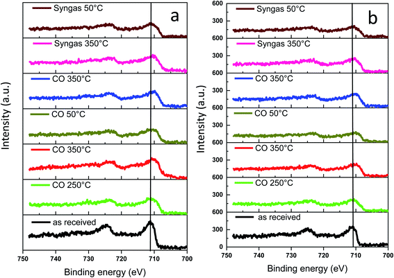 | ||
| Fig. 9 Fe 2p NAP-XPS spectra measured in CO and syngas at different temperatures: (a) FeBi/CNT; (b) Fe/CNT + Bi/CNT. | ||
This observation is consistent with the results of other techniques and indicates the presence of iron oxides in the fresh samples. After the temperature increase in CO to 250 and then to 350 °C, a broad shoulder with the binding energy of 707.3 eV assignable to iron carbide45,46 was detected. Higher intensity of this feature and correspondingly higher amount of iron carbide were observed in syngas (H2/CO = 1) compared to pure CO. The NAP-XPS results in the Fe 2p region are consistent with our previous ex situ XPS data for iron catalysts.16,18 Since the catalysts were supported by CNT, we consider that the intensity of C 1s peak does not change during the experiments. The C 1s intensity was used therefore, as a reference in order to evaluate variation of the relative intensity of Fe 2p XPS peaks during the treatments in CO and syngas at high temperatures. The relative intensities (IFe/IC) are shown in Table 3. No noticeable modification of the intensity of the Fe 2p XPS peaks was observed after exposure of both FeBi/CNT and Fe/CNT + Bi/CNT to carbon monoxide or syngas at 250 °C and 350 °C. Though iron sintering was observed by both in situ and ex situ STEM in iron catalysts during catalyst activation and reaction, NAP-XPS does not show any major increase in iron particle size. Indeed, Table 3 displays only relatively small variation of the relative iron intensity in the activated and spent catalysts. Insignificant iron sintering can be also due to the low gas pressure (1 mbar) used in NAP-XPS experiments compared to in situ STEM (1 bar) or XANES (1–10 bar).
| Catalyst | Gas | Temperature, °C | I Fe/IC | I Bi/IFe |
|---|---|---|---|---|
| FeBi/CNT | CO | 50 | 0.319 | 0.141 |
| 250 | 0.290 | 0.085 | ||
| 350 | 0.389 | 0.038 | ||
| 50 | 0.240 | 0.026 | ||
| 350 | 0.287 | 0.025 | ||
| H2/CO = 1 | 350 | 0.306 | 0.028 | |
| 50 | 0.257 | 0.042 | ||
| Fe/CNT + Bi/CNT | CO | 50 | 0.216 | 0.165 |
| 250 | 0.177 | 0.148 | ||
| 350 | 0.193 | 0.037 | ||
| 50 | 0.155 | 0.064 | ||
| 350 | 0.172 | 0.010 | ||
| H2/CO = 1 | 350 | 0.204 | 0.051 | |
| 50 | 0.198 | 0.040 |
The Bi 4f XPS spectra of the bismuth promoted iron catalysts are shown in Fig. 10. The calcined catalysts exhibit XPS peaks with binding energies of 158.6 and 165 eV assigned to Bi 4f7/2 and Bi 4f5/2 bands in Bi2O3,47,48 respectively. Catalyst activation in carbon monoxide at 250 °C leads to the Bi reduction to metallic state49 with the shift of the characteristic Bi 4f7/2 peak from 158.6 to 156.9 eV. The bismuth reduction observed by NAP-XPS at around 250 °C is consistent with in situ XANES measured at the Bi L3-absorption edge (Fig. S9 and S10, ESI,†Table 1).
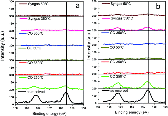 | ||
| Fig. 10 Bi 4f NAP-XPS spectra measured in CO and syngas at different temperatures: (a) FeBi/CNT; (b) Fe/CNT + Bi/CNT. | ||
Interestingly, a further temperature increase to 350 °C in the NAP-XPS experiments results in a major decrease in the intensity of the Bi 4f7/2 and Bi 4f5/2 doublet peaks in both FeBi/CNT and Fe/CNT + Bi/CNT (Table 3). This could be indicative of a major decrease in the bismuth surface and sub-surface concentrations in both catalysts prepared by co-impregnation and mechanical mixing, probably because of bismuth sintering. Note that this major decrease in bismuth surface concentrations detected by XPS coincides with the Bi reduction from oxide to metallic state. Remarkably, different relative localization of iron carbide and bismuth in the catalysts prepared by co-impregnation and mechanical mixing does not affect bismuth sintering. Minimization of surface area is a major thermodynamic driving force for sintering of bismuth nanoparticles, while higher diffusivity of liquid metallic bismuth at temperature higher or comparable to the Bi melting point significantly decreases the kinetic barrier for the migration. Higher diffusivity of liquid bismuth results on one hand, in the major bismuth sintering and on the other hand, in the formation of bismuth–iron carbide core–shell structures in the activated and spent iron catalysts as detected by STEM-EDX (Fig. S11, ESI†). Low intensity of the bismuth XPS signal after the pretreatment in CO and syngas in NAP-XPS experiments was the major reason, why we did not see Bi reoxidation in CO by XPS at ambient temperature. The Bi reoxidation in the activated FeBi/CNT catalyst at ambient temperature in CO was observed by XANES.
Higher diffusivity and mobility of liquid metallic bismuth at the conditions of catalyst activation in CO and FT reaction could also result in the bismuth infiltration inside CNT. Indeed, migration of Bi from outer surface to inside CNT would result in lower intensity of the Bi XPS signal. In order to provide further insights into migration of bismuth under activation in CO, we measured ex situ TEM images of the Bi/CNT sample after exposure to CO at 250 and 350 °C (Fig. 11). Small bismuth nanoparticles of 5–10 nm were detected in the fresh Bi/CNT calcined in nitrogen (Fig. 11a and S1, ESI†). Slightly larger Bi nanoparticles were observed in the same sample after exposure to CO at 250 °C (Fig. 11b). Further increase in the temperature during the pretreatment in CO results in a spectacular growth of Bi nanoparticles (Fig. 11c). The TEM images show the presence of very large spherical Bi particles (>50 nm) in Bi/CNT exposed to CO at 350 °C. Exposure of Bi/CNT to CO at 350 °C results in formation of liquid metallic Bi, which has very high diffusivity over the CNT support. No bismuth infiltration inside CNT was observed.
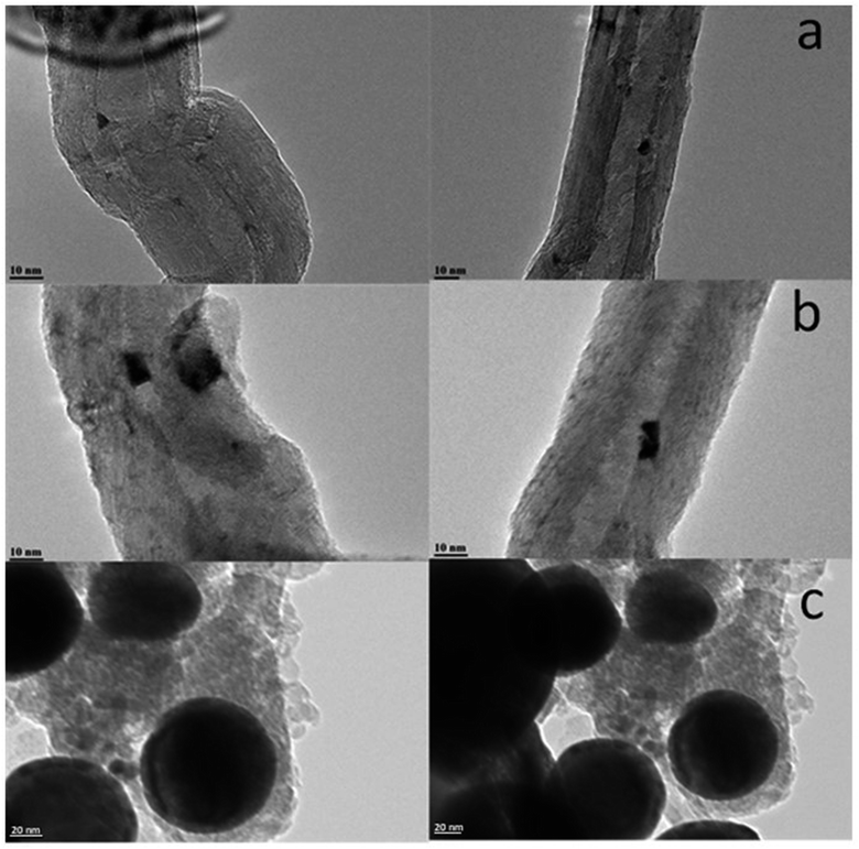 | ||
| Fig. 11 TEM images of Bi/CNT (2 wt%) after calcination in nitrogen (a), after the pretreatments in CO at 250 °C (b) and at 350 °C (c). | ||
Versatility of bismuth-promoted iron catalysts for FT synthesis
Several promoters such as potassium, copper and manganese have been previously proposed10,50–53 to improve the performance of iron FT catalysts. In our work, we present a new strategy focused on the improvement of the catalytic performance of iron catalysts for FT synthesis, which is based on mobile and versatile promoters, such as bismuth. In contrast to the conventional promoters, which are usually considered immobile and localized over specific catalyst sites, metallic bismuth is liquid under FT reaction conditions and freely diffuses on the catalyst surface. The use of this novel liquid promoter results in major (several-fold) increase in FT reaction rate and in higher selectivity to light olefins over iron catalysts.The characterization of iron catalysts with extremely mobile liquid promoters represents however, significant challenge. Indeed, because of high mobility during catalyst activation and under the reaction conditions, this novel type of highly mobile promoters requires advanced in situ time-resolved characterization tools operating at higher temperature and under reacting gas, where the promoters are present in liquid state. Continuous monitoring of evolving bismuth localization over the iron catalysts and switching between different oxidation states at the reaction temperature and in the presence of reacting gas is extremely important for elucidation of the mechanism of bismuth promotion.
A complete picture of the evolution and migration of bismuth promoters has been developed in this work using a combination of in situ characterization techniques (Fig. 12). In situ STEM conducted under atmospheric pressure of reacting gas is indicative of iron sintering occurring during catalyst activation and catalytic reaction. The sintering under these conditions is almost unaffected by the Bi promotion. The bismuth mobility is sharply enhanced after the catalyst pretreatment in carbon monoxide, which results in bismuth reduction. The melting point of metallic bismuth is situated at 271 °C, while bismuth oxide (Bi2O3) melts at 817 °C. Thus, the bismuth mobility in iron catalysts is significantly improved after the reduction of bismuth oxide and melting of metallic bismuth at the temperatures of catalyst activation. Bismuth migration also occurred in the Fe/CNT + Bi/CNT catalysts prepared by mechanical mixing and resulted in a major increase of the activity of mechanically mixed catalyst (Table 1) compared to the reference monometallic Fe/CNT counterpart.
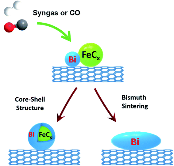 | ||
| Fig. 12 Bismuth migration during activation of iron catalysts and under the conditions of FT synthesis. | ||
Two phenomena relevant to the bismuth migration were observed by combination of in situ techniques. First, melting of metallic bismuth results in formation of relatively large spherical droplets (>50 nm, Fig. 11c). The increase in the Bi droplet size is driven by the decrease in the bismuth surface energy, while liquid state of bismuth significantly reduces the kinetic barrier for its migration over the catalyst surface. Second, interaction of the migrating bismuth species with iron results in the formation of iron bismuth core shell species, which were identified in the activated and spent catalysts by STEM-EDX cartography (Fig. S11†). Important, ICP analysis (Table S1, ESI†) shows no bismuth evaporation during FT reaction.
The interaction and proximity of iron carbide and promoter are extremely important for the Bi oxidation–reduction behavior during the reaction. Important, the Bi oxidation after the contact with CO has been only observed at ambient temperature (Fig. 5 and 6). It is known that CO dissociation42 can proceed relatively easily over iron carbide nanoparticles. At ambient temperature, CO dissociation results into diffusion of adsorbed oxygen species toward bismuth followed by bismuth oxidation (Fig. 8 and 12). At higher temperature, oxygen species produced via CO dissociation over iron carbide and localized over Bi species are easily reduced by reaction with CO yielding CO2. The direct observation of Bi oxidation by CO at room temperature observed by XANES was consistent with previous transient kinetic experiments.17 The conducted steady-state isotopic transient kinetic analysis (SSITKA) experiments suggest that the rates of carbon monoxide adsorption and dissociation are enhanced over the bismuth promoted iron catalysts. In addition, the rates of carbon dioxide production via the Boudouard reaction after the exposure of the catalyst to CO at 350 °C were also much higher over the Bi-promoted catalysts in comparison to the unpromoted counterpart. This suggests that the rates of oxygen scavenging and its removal via its reaction with carbon monoxide are significantly enhanced in the presence of bismuth. The effect of bismuth on the FT reaction rate is more pronounced at atmospheric pressure when the rates of CO adsorption and dissociation are relatively lower.
The new strategy based on the use of liquid metallic promoters, such as bismuth, has several advantages in comparison to the conventional immobile promoters for enhancement of catalytic performance of supported metallic catalysts. First, the promoting effects of liquid promoters relative to the immobile counterparts are reinforced by the promoter migration during the catalyst activation and its preferential localization at the surface of iron carbide nanoparticles leading to the formation of core–shell structures with the active phase. Second, the close contact (easily achievable because of the migration) between the iron active phase and liquid promoter may result in the promoter direct involvement in the elementary steps of FT synthesis such as carbon monoxide dissociation. This results in several fold increase in the intrinsic activity (TOF). FT synthesis over the promoted iron catalysts can be conducted with substantial conversion even at atmospheric pressure. The selectivity to light olefins over the catalysts promoted with liquid metals such as bismuth and lead,17,19 has been significantly increased. Third, easy reoxidation and reduction of bismuth species at the interface with the active phase may improve the catalyst stability and slow down carbon deposition. Promising results relevant to the enhanced stability in syngas conversion reactions have been recently obtained54 for cobalt and nickel catalysts promoted with bismuth.
Conclusion
The strategy focused on the use of the bismuth liquid promoter with extremely high mobility is proposed for enhancement of the catalytic performance of CNT supported iron catalysts for FT synthesis. The catalyst evolution has been elucidated using a combination of the cutting-edge characterization techniques. Under the conditions of catalyst activation and reaction, metallic bismuth migrates over the catalyst surface forming larger spherical bismuth droplets, strongly interacts with iron carbide species and forms core–shell mixed nanoparticles.Carbon monoxide activation over the Bi-promoted iron catalysts is enhanced by oxygen scavenging and reversible oxidation of bismuth species localized in a close proximity to iron carbide nanoparticles. The bismuth redox cycles directly observed by in situ XANES leads to the enhanced performance of the promoted iron catalysts in FT synthesis.
Sintering of iron carbide species under the catalyst activation occurred according to particle migration and coalescence mechanism and was directly observed by in situ STEM operating under atmospheric pressure of CO at the temperatures of catalyst activation.
Experimental
The Fe/CNT and Bi/CNT catalyst were prepared by impregnation with respectively iron and bismuth nitrates. The FeBi/CNT catalyst was prepared by impregnation using solutions of iron and bismuth nitrate. The Fe/CNT + Bi/CNT sample was prepared by mechanical mixing of the Fe/CNT and Bi/CNT catalysts. The samples were calcined in nitrogen at 400 °C to decompose relevant nitrates. The CNT treatment and catalyst preparation details are given in ESI.†The BET surface area, pore volume and pore diameter were determined with low temperature N2 adsorption–desorption experiments performed on a Micromeritics Tristar Model 3020 Surface Area and Porosimetry analyzer. The samples (100 mg) were degassed under vacuum at 250 °C for 2 h prior to N2 physisorption.
The X-ray diffraction patterns (XRD) were recorded on a PANalytical Empyrean X-ray diffractometer in Bragg–Brentano configuration with the 0.02° step size and 1 s step time. The Cu Kα radiation (40 kV and 30 mA) was used as the X-ray source. The crystalline phases were identified by comparing the diffraction patterns with those of the standard powder XRD files (JCPDS). The crystallite average size was calculated using the Scherrer equation. In situ XRD measurements were conducted under H2 (3%)/N2 on a D8 Bruker diffractometer equipped with an Anton Paar XRK900 reactive chamber. Data were acquired in the Bragg–Brentano geometry, using the Cu Kα radiation (40 kV, 40 mA). Diffractograms were recorded every 25![[thin space (1/6-em)]](https://www.rsc.org/images/entities/char_2009.gif) °C from 50 to 700
°C from 50 to 700![[thin space (1/6-em)]](https://www.rsc.org/images/entities/char_2009.gif) °C.
°C.
The Fe and Bi elemental analyses were performed by inductively coupled plasma-optic emission spectroscopy 720-ES ICP-OES (Agilent) with axially viewing and simultaneous CCD detection.
The catalyst reduction behavior was studied through the H2 temperature-programmed reduction (H2-TPR), which was carried out using the AutoChem II 2920 apparatus (Micromeritics). In a typical experiment, 100 mg sample was treated with H2/Ar (5 vol% H2) stream (50 ml min−1) with the temperature raising from room temperature to 900 °C at the rate of 10 °C min−1.
Transmission electron microscopy (TEM) analysis was carried out on a Jeol 2100F (field emission gun) microscope operating at 200 kV equipped with a spherical aberrations STEM probe corrector and a Centurion EDX detector. Before analysis, the samples were dispersed in ethanol and deposited on a holey carbon coated TEM grid. More than 100 particles were counted to estimate the average Fe particle size and standard deviation from TEM images. For the in situ environmental gas TEM analyses, the catalyst powders were crushed, then dispersed in pure ethanol and drop casted onto the environmental cell membrane of a Protochips Atmosphere holder. In order to obtain the highest possible contrast between the particles and the supports, the scanning TEM with high angle-annular dark field imaging mode was preferentially used. Several locations on the grid were tagged during sample examination at room temperature. The same regions were further observed after heating the sample with different gas (Ar, CO and syngas) at atmospheric pressure.
NAP-XPS analyses were performed in a custom-built NAP-XPS (SPECS Surface Nano Analysis, GmbH Germany).31 The apparatus was equipped with a PHOIBOS 150 Hemispheric Energy Analyser coupled with a differentially pumped electrostatic pre-lens system for spectra collection and an Al Kα monochromatic X-ray source of high intensity (excitation energy of 1486.6 eV). In the XPS analysis chamber, the in situ reaction cell allowed XPS measurements in presence of gas with pressure up to 10 mbar and at high temperature. The measurements were performed in presence of CO and syngas (1 mbar) at temperatures ranging from ambient to 350 °C on samples pressed into a tungsten mesh that was fixed on the sample holder. The data were analyzed with the CasaXPS software.
The in situ Bi L3-edge X-ray absorption fine structure (XAFS) spectra were measured at the beamline BM26A of the ESRF (Grenoble, France) using a Si (111) double-crystal fast scanning monochromator. The known amount of catalyst (3–5 mg) was loaded in the quartz capillary (OD = 1 mm, wall thickness = 0.020 mm) and pressed from both sides with quartz wool. The capillary reactor used for in situ XANES measurements was attached to the stainless-steel holder using high temperature epoxy glue. A Cyberstar gas blower was used to control the capillary reactor temperature. The total pressure in the reactor (up to 10 bar) was regulated by a back-pressure controller. The products were analyzed online with gas chromatograph (Bruker GC-450). The data were analyzed with the Athena software.
The catalytic performance of CNT-supported iron catalysts was evaluated in the capillary cell (Fig. S8, ESI†), which was used for in situ XANES measurements, with a pre-bed reactor. The catalyst loadings were 100 mg for the pre-bed and 3–5 mg for the capillary reactors, respectively. All the in situ XAS experiments with simultaneous analysis of the FT reaction products were performed at the reaction pressure of 10 bar. After the XAS experiment, the pressure was decreased to atmospheric and the catalytic performance was also evaluated 350 °C under atmospheric pressure. We did not measure XAS at atmospheric pressure. N2 was used as an internal standard. Analysis of N2, CO, CO2, and CH4 was performed using CTR-1 column, while hydrocarbons were separated on Rt-Q-PLOT capillary column. Iron time yields (FTY) were expressed as moles of CO converted per gram of total iron per second. The CO2 free hydrocarbon selectivities are calculated on carbon basis. The carbon balance was better than 90%.
Conflicts of interest
No conflict of interest to declare.Acknowledgements
The authors thank Laurence Burylo for help with XRD measurements. The authors acknowledge financial support from the European Union (Interreg FWVL project PSYCHE) and French National Research Agency (NANO4FUT, Ref. ANR-16-CE06-0013). B. G is grateful to Chinese Scholarship Council for giving him a stipend for PhD studies in France. The authors acknowledge the CERIC-ERIC Consortium for the access to experimental facilities and financial support. The authors thank the ESRF synchrotron for using the beam time.References
- A. Zavabeti, J. Z. Ou, B. J. Carey, N. Syed, R. Orrell-Trigg, E. L. H. Mayes, C. Xu, O. Kavehei, A. P. O'Mullane, R. B. Kaner, K. Kalantar-zadeh and T. Daeneke, Science, 2017, 358, 332–335 CrossRef CAS PubMed.
- T. Daeneke, K. Khoshmanesh, N. Mahmood, I. A. de Castro, D. Esrafilzadeh, S. J. Barrow, M. D. Dickey and K. Kalantar-zadeh, Chem. Soc. Rev., 2018, 47, 4073–4111 RSC.
- N. Raman, S. Maisel, M. Grabau, N. Taccardi, J. Debuschewitz, M. Wolf, H. Wittkämper, T. Bauer, M. Wu, M. Haumann, C. Papp, A. Görling, E. Spiecker, J. Libuda, H. P. Steinrück and P. Wasserscheid, ACS Catal., 2019, 9, 9499–9507 CrossRef CAS PubMed.
- N. Taccardi, M. Grabau, J. Debuschewitz, M. Distaso, M. Brandl, R. Hock, F. Maier, C. Papp, J. Erhard, C. Neiss, W. Peukert, A. Görling, H. P. Steinrück and P. Wasserscheid, Nat. Chem., 2017, 9, 862–867 CrossRef CAS PubMed.
- M. Wolf, N. Raman, N. Taccardi, M. Haumann and P. Wasserscheid, ChemCatChem, 2020, 12, 1085–1094 CrossRef CAS PubMed.
- D. C. Upham, V. Agarwal, A. Khechfe, Z. R. Snodgrass, M. J. Gordon, H. Metiu and E. W. McFarland, Science, 2017, 358, 917–921 CrossRef CAS PubMed.
- H. Shou, L. Li, D. Ferrari, D. S. Sholl and R. J. Davis, J. Catal., 2013, 299, 150–161 CrossRef CAS.
- A. J. Rouco, J. Catal., 1995, 157, 380–387 CrossRef CAS.
- B. K. Olsen, F. Kügler, F. Castellino and A. D. Jensen, Catal. Sci. Technol., 2016, 6, 2249–2260 RSC.
- H. M. Torres Galvis and K. P. de Jong, ACS Catal., 2013, 3, 2130–2149 CrossRef CAS.
- H. M. Torres Galvis, J. H. Bitter, C. B. Khare, M. Ruitenbeek, A. I. Dugulan and K. P. de Jong, Science, 2012, 335, 835–838 CrossRef CAS PubMed.
- H. Jung, J. Catal., 1982, 75, 416–422 CrossRef CAS.
- E. de Smit and B. M. Weckhuysen, Chem. Soc. Rev., 2008, 37, 2758 RSC.
- P. A. Jacobs and H. K. Beyer, J. Phys. Chem., 1979, 83, 1174–1177 CrossRef CAS.
- H. J. Schulte, B. Graf, W. Xia and M. Muhler, ChemCatChem, 2012, 4, 350–355 CrossRef CAS.
- B. Gu, V. V. Ordomsky, M. Bahri, O. Ersen, P. A. Chernavskii, D. Filimonov and A. Y. Khodakov, Appl. Catal., B, 2018, 234, 153–166 CrossRef CAS.
- V. V. Ordomsky, Y. Luo, B. Gu, A. Carvalho, P. A. Chernavskii, K. Cheng and A. Y. Khodakov, ACS Catal., 2017, 7, 6445–6452 CrossRef CAS.
- B. Gu, S. He, D. V. Peron, D. R. Strossi Pedrolo, S. Moldovan, M. C. Ribeiro, B. Lobato, P. A. Chernavskii, V. V. Ordomsky and A. Y. Khodakov, J. Catal., 2019, 376, 1–16 CrossRef CAS.
- A. J. Barrios, B. Gu, Y. Luo, D. V Peron, P. A. Chernavskii, M. Virginie, R. Wojcieszak, J. W. Thybaut, V. V Ordomsky and A. Y. Khodakov, Appl. Catal., B, 2020, 273, 119028 CrossRef CAS.
- G. Jacobs, W. Ma, P. Gao, B. Todic, T. Bhatelia, D. B. Bukur and B. H. Davis, Catal. Today, 2013, 214, 100–139 CrossRef CAS.
- M. C. Ribeiro, G. Jacobs, B. H. Davis, D. C. Cronauer, A. J. Kropf and C. L. Marshall, J. Phys. Chem. C, 2010, 114, 7895–7903 CrossRef CAS.
- C. Garino, E. Borfecchia, R. Gobetto, J. A. van Bokhoven and C. Lamberti, Coord. Chem. Rev., 2014, 277–278, 130–186 CrossRef CAS.
- A. I. Frenkel, A. Yevick, C. Cooper and R. Vasic, Annu. Rev. Anal. Chem., 2011, 4, 23–39 CrossRef CAS PubMed.
- S. Bordiga, E. Groppo, G. Agostini, J. A. van Bokhoven and C. Lamberti, Chem. Rev., 2013, 113, 1736–1850 CrossRef CAS PubMed.
- F. Tao and P. A. Crozier, Chem. Rev., 2016, 116, 3487–3539 CrossRef CAS PubMed.
- L. F. Allard, S. H. Overbury, W. C. Bigelow, M. B. Katz, D. P. Nackashi and J. Damiano, Microsc. Microanal., 2012, 18, 656–666 CrossRef CAS.
- S. B. Vendelbo, C. F. Elkjær, H. Falsig, I. Puspitasari, P. Dona, L. Mele, B. Morana, B. J. Nelissen, R. van Rijn, J. F. Creemer, P. J. Kooyman and S. Helveg, Nat. Mater., 2014, 13, 884–890 CrossRef CAS.
- Y. Li, D. Zakharov, S. Zhao, R. Tappero, U. Jung, A. Elsen, P. Baumann, R. G. Nuzzo, E. A. Stach and A. I. Frenkel, Nat. Commun., 2015, 6, 7583 CrossRef CAS.
- L. Nguyen, F. F. Tao, Y. Tang, J. Dou and X.-J. Bao, Chem. Rev., 2019, 119, 6822–6905 CrossRef PubMed.
- D. I. Patel, T. Roychowdhury, V. Jain, D. Shah, T. G. Avval, S. Chatterjee, S. Bahr, P. Dietrich, M. Meyer, A. Thißen and M. R. Linford, Surf. Sci. Spectra, 2019, 26, 016801 CrossRef.
- M. Vorokhta, I. Khalakhan, M. Vondráček, D. Tomeček, M. Vorokhta, E. Marešová, J. Nováková, J. Vlček, P. Fitl, M. Novotný, P. Hozák, J. Lančok, M. Vrňata, I. Matolínová and V. Matolín, Surf. Sci., 2018, 677, 284–290 CrossRef CAS.
- K. Cheng, M. Virginie, V. V. Ordomsky, C. Cordier, P. A. Chernavskii, M. I. Ivantsov, S. Paul, Y. Wang and A. Y. Khodakov, J. Catal., 2015, 328, 139–150 CrossRef CAS.
- W. Chen, Z. Fan, X. Pan and X. Bao, J. Am. Chem. Soc., 2008, 130, 9414–9419 CrossRef CAS PubMed.
- C. H. Bartholomew, Appl. Catal., A, 2001, 212, 17–60 CrossRef CAS.
- C. H. Bartholomew, Appl. Catal., A, 1993, 107, 1–57 CrossRef CAS.
- S. B. Simonsen, I. Chorkendorff, S. Dahl, M. Skoglundh, J. Sehested and S. Helveg, J. Am. Chem. Soc., 2010, 132, 7968–7975 CrossRef CAS PubMed.
- M. Sadeqzadeh, J. Hong, P. Fongarland, D. Curulla-Ferré, F. Luck, J. Bousquet, D. Schweich and A. Y. A. Y. Khodakov, Ind. Eng. Chem. Res., 2012, 51, 11955–11964 CrossRef CAS.
- I. M. Lifshitz and V. V. Slyozov, J. Phys. Chem. Solids, 1961, 19, 35–50 CrossRef.
- A. K. Datye, Q. Xu, K. C. Kharas and J. M. McCarty, Catal. Today, 2006, 111, 59–67 CrossRef CAS.
- M. Seipenbusch and A. Binder, J. Phys. Chem. C, 2009, 113, 20606–20610 CrossRef CAS.
- C.-F. Huo, Y.-W. Li, J. Wang and H. Jiao, J. Am. Chem. Soc., 2009, 131, 14713–14721 CrossRef CAS.
- M. Ojeda, R. Nabar, A. U. Nilekar, A. Ishikawa, M. Mavrikakis and E. Iglesia, J. Catal., 2010, 272, 287–297 CrossRef CAS.
- V. V. Ordomsky, B. Legras, K. Cheng, S. Paul and A. Y. Khodakov, Catal. Sci. Technol., 2015, 5, 1433–1437 RSC.
- M. D. Shroff, D. S. Kalakkad, K. E. Coulter, S. D. Kohler, M. S. Harrington, N. B. Jackson, A. G. Sault and A. K. Datye, J. Catal., 1995, 156, 185–207 CrossRef CAS.
- J. B. Butt, Catal. Lett., 1991, 7, 61–81 CrossRef.
- C. Yang, H. Zhao, Y. Hou and D. Ma, J. Am. Chem. Soc., 2012, 134, 15814–15821 CrossRef CAS PubMed.
- C. Wang, C. Shao, Y. Liu and L. Zhang, Scr. Mater., 2008, 59, 332–335 CrossRef CAS.
- Y. Schuhl, H. Baussart, R. Delobel, M. Le Bras, J.-M. Leroy, L. Gengembre and J. Grimblot, J. Chem. Soc., Faraday Trans. 1, 1983, 79, 2055 RSC.
- C. Chang, L. Zhu, Y. Fu and X. Chu, Chem. Eng. J., 2013, 233, 305–314 CrossRef CAS.
- R. A. Dictor and A.T. Bell, J. Catal., 1986, 97, 121–136 CrossRef CAS.
- D. B. Bukur, D. Mukesh and S. A. Patel, Ind. Eng. Chem. Res., 1990, 29, 194–204 CrossRef CAS.
- C. Zhang, Y. Yang, B. Teng, T. Li, H. Zheng, H. Xiang and Y. Li, J. Catal., 2006, 237, 405–415 CrossRef CAS.
- B. Hu, S. Frueh, H. F. Garces, L. Zhang, M. Aindow, C. Brooks, E. Kreidler and S. L. Suib, Appl. Catal., B, 2013, 132–133, 54–61 CrossRef CAS.
- B. Gu, M. Bahri, O. Ersen, A. Khodakov and V. V. Ordomsky, ACS Catal., 2019, 9, 991–1000 CrossRef CAS.
Footnote |
| † Electronic supplementary information (ESI) available. See DOI: 10.1039/d0sc01600d |
| This journal is © The Royal Society of Chemistry 2020 |

