 Open Access Article
Creative Commons Attribution 3.0 Unported Licence
Controlled colloidal metal nanoparticles and nanoclusters: recent applications as cocatalysts for improving photocatalytic water-splitting activity
Tokuhisa
Kawawaki
 ab,
Yutaro
Mori
a,
Kosuke
Wakamatsu
a,
Shuhei
Ozaki
a,
Masanobu
Kawachi
a,
Sakiat
Hossain
 a and
Yuichi
Negishi
 *ab
*ab
aDepartment of Applied Chemistry, Faculty of Science, Tokyo University of Science, 1-3 Kagurazaka, Shinjuku-ku, Tokyo 162-8601, Japan. E-mail: negishi@rs.tus.ac.jp; Fax: +81-3-5261-4631; Tel: +81-3-5228-9145
bResearch Institute for Science & Technology, Tokyo University of Science, 1-3 Kagurazaka, Shinjuku-ku, Tokyo 162-8601, Japan
First published on 27th July 2020
Abstract
In recent years, research on the use of metal nanoparticles (NPs) and nanoclusters (NCs) synthesized by liquid-phase reduction in water-splitting photocatalysts has been actively conducted. Water-splitting photocatalysts have been attracting attention because they can produce hydrogen (H2), which is attractive as a next-generation energy source, from solar energy and water. However, further improvement of water-splitting photocatalysts is required for their practical use in society. Recent studies have demonstrated that the active sites (cocatalysts) of water-splitting photocatalysts can be controlled using the advanced NP/NC syntheses and structural modulation techniques established in the fields of colloid, NP, and NC chemistry and thereby highly active water-splitting photocatalysts can be developed. If such research progresses further, it is expected that a transition to a new society using H2 as the main energy source will become possible. However, such applied research has just started and examples of such research are currently limited. The purpose of this review is to introduce the importance of controlled colloidal NPs/NCs in research on water-splitting photocatalysis to readers by summarizing the existing research. We hope that this review will raise interest in the application of metal NPs/NCs in water-splitting photocatalysis and that a society actively addressing energy and environmental problems will become a reality as soon as possible.
1. Introduction
1.1. Metal nanoparticles and nanoclusters
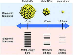
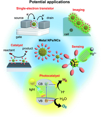
The nanometer scale is the smallest on which the function of a material appears. Therefore, if a material can be controlled at the nanometer scale, almost all the properties of the material can be regulated. Furthermore, it is possible to produce new physical/chemical properties and functions different from those of the bulk material by controlling the atomic array structure (crystal structure) at the nanometer scale. Because of the importance of and interest in producing nanomaterials with intended structure and function, technology to control nanomaterials (i.e., nanotechnology) is being promoted as a national policy in many countries.Metal nanoparticles (NPs) (Fig. 1),1,2 which are aggregates of metal atoms, play a central role in such nanotechnology research. Research on metal NPs was initiated by Faraday in the 1840s in his investigation of metal colloids.3 Since the 1980s, the research on metal colloids has progressed substantially and the expression “metal NPs” has been coined.4–23 In the last two decades, research on metal NPs has increased explosively, and the techniques to synthesize metal NPs have advanced dramatically. In recent years, it has become possible to control not only the size of metal NPs but also their geometrical structure. Metal NPs composed of coinage metals such as gold (Au), silver (Ag), and copper (Cu) exhibit localized surface plasmon resonance absorption in the visible region (Fig. 1),23–27 which makes these NPs even more attractive. Because of these properties, metal NPs can be used in surface-enhanced Raman spectroscopy.28 Therefore, studies on the use of metal NPs to detect trace amounts of molecules are being conducted for applications.29 In addition, techniques to control the arrangement of metal NPs have been established,30 which has opened the way to apply metal NPs in the field of electronic devices. Furthermore, metal NPs are also expected to be useful in biotechnology applications such as drug delivery systems and diagnosis (Fig. 2).31
Metal nanoclusters (NCs), as shown in Fig. 1, are smaller in size than metal NPs and are also important materials in nanotechnology.32,33 There is no clear definition of the boundary between metal NPs and metal NCs. However, when the particle size is less than 2 nm, the materials are generally called metal NCs (Fig. 1). Such ultrafine metal NCs possess electronic and geometrical structures that are different from those of both the corresponding bulk metal and metal NPs, which leads to the appearance of new physical/chemical properties and functions (Fig. 1).34–45 Furthermore, because the physical/chemical properties and functions of NCs strongly depend on the number of constituent atoms, if the number of constituent atoms in metal NCs can be controlled, numerous functions can be realized by one metal element. When multiple elements are used in NCs, it is possible to access further various functions.46–56
Gas-phase experiments played a leading role in research on metal NCs in the 1980s and 90s.57–69 Also, the synthesis of metal NCs composed of gold, palladium (Pd), and platinum (Pt) started at that time.70–78 However, it was only after 2000 that research on these NCs began to increase explosively.79 In 2005, the first precise synthesis method for thiolate (SR)-protected metal NCs was established.80 Since then, numerous noble metal and alloy NCs have been precisely synthesized using SR, phosphine, and alkyne ligands.81–109 Since 2007, it has become possible to determine the geometrical structure of NCs by single-crystal X-ray diffraction (XRD) analysis.110–114 Thus, at present, inorganic chemists precisely synthesize SR-protected metal NCs as organic chemists synthesize organic molecules. It is possible to obtain a deep understanding of the structure–property relationship of metal NCs with precisely determined geometrical structure.82–114 The use of these well-defined NCs as catalysts, chemical sensors, photosensitizers, and solar cell components is currently being studied (Fig. 2).34,79,115–122
In this way, the syntheses and applications are being actively investigated for metal NPs and metal NCs at present. Multiple reviews have been published on the recent research development of such metal NPs and NCs.34,79,115–122 Readers hoping to obtain comprehensive knowledge of the synthesis techniques of metal NPs/NCs, their geometrical structures, and potential applications should refer to these reviews.
1.2. Application of metal NPs/NCs as cocatalysts in water-splitting photocatalysts
This review outlines the research on the use of metal NPs/NCs in the field of water-splitting photocatalysis, in which many groups have begun to work in recent years (Fig. 2). With the depletion of fossil resources and the aggravation of climate change, the transition from a society that depends on fossil fuels to one that uses clean and renewable energy is needed. Hydrogen (H2) releases a large amount of energy upon combustion. In addition, the combustion of H2 generates only water, which does not pollute the environment. Thus, H2 has great potential as a new energy source that solves energy and environmental problems (Fig. 3).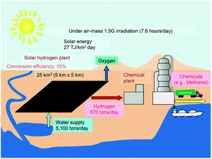 | ||
| Fig. 3 Possible scheme for large-scale H2 production via solar water splitting. Reproduced with permission from ref. 124. Copyright 2010 American Chemical Society. | ||
Most H2 is currently produced by steam reforming of fossil resources. However, this method releases carbon dioxide as a byproduct and consumes fossil resources. Therefore, if H2 continues to be produced by this method, it will not provide a solution for both energy and environmental problems. The water-splitting photocatalytic reaction123 has been proposed as a clean and renewable H2 production method (Fig. 3).124 Using this reaction, it is possible to produce H2 from sunlight and water, which are available in almost unlimited quantities on the earth. This is different from the case of the water-splitting electrocatalytic reaction125–128 in which electric power is consumed to proceed the reaction (thus, the combination with the solar cells is indispensable in this case129,130). However, although water-splitting photocatalysts have been attracting attention for many years, further improvement is still required to realize their practical use.
Water-splitting semiconductor photocatalysts are often composed of semiconductor photocatalysts and metal NP/NC cocatalysts that work as reaction sites (Fig. 4).131 The cocatalyst plays a role in promoting the photocatalytic reaction, and it has been shown that control of the cocatalyst particle size and dispersion improves photocatalytic activity. However, it is difficult to control the particle size and chemical composition of cocatalysts loaded using conventional photodeposition and impregnation methods because the metal NPs/NCs are grown on the surface of the photocatalyst in these methods (Fig. 5A).132,133 To overcome these problems and produce highly active water-splitting photocatalysts suitable for practical use, it is essential to introduce new techniques for the preparation of water-splitting photocatalysts.
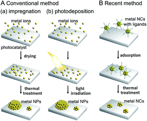 | ||
| Fig. 5 Comparison of (A) conventional and (B) recent cocatalyst loading methods. As conventional methods, (a) impregnation and (b) photodeposition methods are shown in (A). | ||
As described in Section 1.1, techniques to control the particle size distribution of metal NPs fabricated by liquid-phase synthesis have already been established. When such controlled metal NPs are adsorbed on a photocatalyst and the surface protective organic molecules (ligand, polymer, etc.) are removed, it is possible to obtain controlled metal NP-loaded photocatalysts with high water-splitting activity (Fig. 5B).132,133 When precisely controlled metal NCs are used as the precursor, it is possible to regulate the cocatalyst on a photocatalyst with atomic precision.134–136 For such precise metal NCs, detailed information about electronic and geometrical structures can be obtained by various high-resolution measurements and theoretical calculations, as shown in the previous studies on the supported metal NPs/NCs.118,137 Therefore, loading the cocatalyst controlled with atomic accuracy would lead to the clear design guidelines for high activation of water-splitting photocatalysts. If appropriate metal NCs are designed and fabricated based on the knowledge obtained in this way, the activity of water-splitting photocatalysts is expected to be further enhanced.
1.3. Purpose of this review
As described in Section 1.2, water-splitting photocatalysts can be activated using cocatalysts fabricated by precise synthesis and structure control techniques (nanotechnology) established in the fields of colloid, NP, and NC chemistry. Such highly active water-splitting photocatalysts could lead to the resolution of energy and environmental problems. However, such applied research has only recently started, and at present the examples are limited. The purpose of this review is to introduce the importance of using controlled colloidal metal NPs/NCs in research on water-splitting photocatalysis by summarizing the existing research. We hope that this review will increase interest in the application of metal NPs/NCs in water-splitting photocatalysts. Ultimately, it is anticipated that the progress of this research will lead to a society in which energy and environmental problems have been solved.1.4. Contents of this review
This review is constituted as follows. First, Section 2 provides an overview of water-splitting photocatalysts. Then, Section 3 outlines the methods used to load cocatalysts. Section 4 presents examples of research using metal NPs/NCs fabricated by liquid-phase synthesis as cocatalysts in water-splitting photocatalysts. In this section, we also present examples of studies using metal NPs/NCs for H2 or O2 production from water (the half reactions of water splitting), although these reactions do not realize complete decomposition of water. Section 5 shows the importance of elucidating the interface between metal NPs/NCs and substrates, and introduces appropriate methods for such a purpose. Section 6 summarizes this review, and Section 7 briefly describes the prospects of metal NPs/NCs in water splitting.It should be noted that there are many studies using NPs/NCs not as active sites but as light absorption sites in water-splitting photocatalysis.138–144 A number of reviews on the use of NPs/NCs as photosensitizers have already been published,37,115 so this review does not cover such research.
2. Water-splitting photocatalysts
2.1. Reaction mechanism
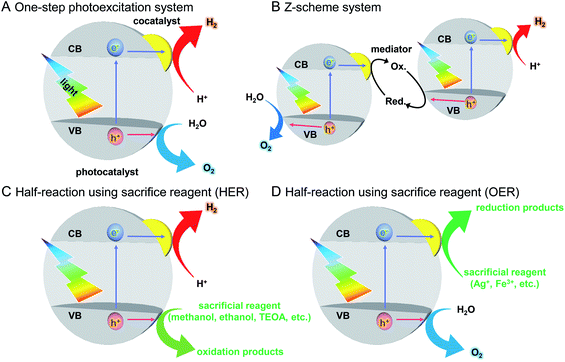
As described in Section 1.2, a water-splitting photocatalyst generally consists of a semiconductor photocatalyst and cocatalyst. When the photocatalyst is irradiated with light, electrons are excited from the valence band (VB) to the conduction band (CB) in the semiconductor photocatalyst. The excited electrons in the CB and holes remaining in the VB move to the photocatalyst surface and/or cocatalyst, where the electrons reduce water and the holes oxidize water (Fig. 4).131,132 Theoretically, if the bottom edge of the CB of the semiconductor photocatalyst is more negative than the reduction potential of water (0 V vs. normal hydrogen electrode; NHE), the reduction reaction of water proceeds and H2 is produced; this is called the H2 evolution reaction (HER). In addition, if the top edge of the VB of the semiconductor photocatalyst is more positive than the oxidation potential of water (1.23 V vs. NHE), the oxidation reaction of water proceeds and O2 is produced, which is called the O2 evolution reaction (OER) (Fig. 6).145–147 However, a semiconductor that satisfies these conditions is not always capable of completely decomposing water (i.e., overall water splitting), which is largely related to the following factors: (i) the high activation energy of water splitting makes it difficult for this reaction to proceed; (ii) the reaction is deactivated by recombination of electrons and holes; and (iii) the produced H2 and O2 can undergo the reverse reaction. Therefore, it is important to suppress these negative factors when designing a cocatalyst. | ||
| Fig. 6 Relationship between the semiconductor band structure and redox potentials of water splitting. Reproduced with permission from ref. 145–147, and 160. Copyright 2009 Royal Society of Chemistry, Copyright 2020 Royal Society of Chemistry, Copyright 2018 Royal Society of Chemistry, and Copyright 2010 American Chemical Society. | ||
2.2. Reaction system
The recent major systems used for the water-splitting reaction are one-step photoexcitation systems148 and two-step photoexcitation systems (i.e., Z-scheme systems).131,132,147,149–152 In addition to these systems, much research has been conducted on the half reactions of water splitting (HER, OER) using sacrificial agents. Here, these reactions are outlined.On the other hand, to realize the practical application of water-splitting photocatalysis, it is necessary to use visible light, which accounts for about 40% of solar energy. As described in Section 2.1, to completely decompose water, the positions of the CB and VB of a photocatalyst must be at appropriate energies to enable the HER and OER, respectively. Furthermore, to suppress recombination of excited electrons and holes, the photocatalyst needs to have high crystallinity and large specific surface area. Because of these requirements, only a limited number of photocatalysts for one-step photoexcitation systems that can completely decompose water with visible light have been reported.151
Z-scheme systems include semiconductor photocatalysts that proceed a half reaction of water splitting (HER or OER). Therefore, compared with the case for one-step photoexcitation systems, there are many photocatalysts available, and it is possible to use a longer wavelength of sunlight. Additionally, because the HER and OER occur on different photocatalysts, it is possible to suppress the reverse reaction between the generated H2 and O2 by using a two-cell reaction tube with an ion-exchange membrane. Also, an operation to separate the generated gas is unnecessary. However, in Z-scheme systems, the reverse reaction involving a redox couple occurs, which is different from the case for one-step photoexcitation systems. Furthermore, because two photons are required for one reaction in overall water splitting, Z-scheme systems have the disadvantage of lower theoretical conversion efficiency than that of one-step photoexcitation systems.
2.3. Semiconductor photocatalyst materials
Semiconductors used as photocatalysts are mainly metal oxides, metal nitrides, and metal sulfides (Fig. 6).131,151 Also, metal-free graphitic carbon nitride (g-C3N4) can be used as a water-splitting photocatalyst.148,156,157 Metal oxides generally have high stability but do not readily absorb visible light because their VB mainly consists of oxygen 2p orbitals and is located to the positive side of the redox potential of the OER. To overcome these problems, the following strategies have been used to modify photocatalysts: (i) metal-ion doping (SrTiO3: Rh, Ir158,159); (ii) formation of solid solutions (GaN:ZnO,160 ZnS–AgInS2–CuInS2,161 La5Ti2Cu0.9Ag0.1S5O7,162 In0.2Ga0.8N,163etc.); (iii) controlling the VB position by including elements other than oxygen (BiVO4,164–166 TaON,167,168 Ta3N5,168etc.); and (iv) using a dye sensitization reagent (Ru(II) complex169).2.4. Cocatalyst materials
The cocatalyst promotes the transfer of electrons and holes generated by photoexcitation and also plays a role in lowering the activation energies of the HER and OER (Fig. 4). Each reaction on the cocatalyst involves the adsorption of the substrate, reaction of the substrate, and desorption of the products. The progress of each reaction is strongly related to the adsorption/desorption energies of the substrate/product on the cocatalyst surface. In particular, the chemical reaction on the cocatalyst surface proceeds easily when the Gibbs energy of formation is moderate for the state where the substrates and products are adsorbed on the cocatalyst. This is because the reaction does not occur without the substrate being adsorbed, but the reaction is inhibited when the adsorption is too strong. Generally, metal or metal oxide NPs composed of group 8–11 elements are used as the cocatalyst because of their suitable binding affinity with substrates. These NPs often have diameters of several to several tens of nanometers.133,170 Additionally, it has recently been reported that MoS2 and WS2![[thin space (1/6-em)]](https://www.rsc.org/images/entities/char_2009.gif) 171 are highly active HER cocatalysts.170 An important point is that metal/metal oxides NPs/NCs that are highly active in the HER and/or OER but also highly active towards the reverse reactions cannot be used as cocatalysts. Metal/metal oxides NPs/NCs are generally active in reverse reactions, so when they are used as cocatalysts, formation of core/shell structure, alloy state, or a solid solution is necessary to suppress the reverse reactions on the cocatalyst surface.147
171 are highly active HER cocatalysts.170 An important point is that metal/metal oxides NPs/NCs that are highly active in the HER and/or OER but also highly active towards the reverse reactions cannot be used as cocatalysts. Metal/metal oxides NPs/NCs are generally active in reverse reactions, so when they are used as cocatalysts, formation of core/shell structure, alloy state, or a solid solution is necessary to suppress the reverse reactions on the cocatalyst surface.147
2.5. Towards practical use
For the practical use of a water-splitting photocatalyst, the conversion efficiency of solar energy to H2 (STH) needs to be at least 10%. However, the current maximum STH for water splitting using semiconductor fine particles is about 1.1%.151,172 Therefore, further improvement of STH is required for the practical use of water-splitting photocatalysts. Among such efforts, the development of visible light-responsive photocatalysts and highly functional cocatalysts are particularly important research subjects. To develop more advanced cocatalysts, it is necessary for the density of active sites to be increased, and the substrate adsorption energy to be optimized by the modulation of the cocatalyst electronic structure. Refinement of the cocatalyst is an effective strategy to achieve both of these characteristics and alloying is also effective for the latter. In addition, techniques for loading fine cocatalyst particles on photocatalysts with high dispersity and improving cocatalyst durability are also important for practical application of water-splitting photocatalysts.3. Cocatalyst loading methods
3.1. Conventional methods
In previous studies, cocatalysts have been loaded on photocatalysts by impregnation and photodeposition methods. These loading methods are widely used because of their simplicity.The impregnation method (Fig. 5A(a)) was first used for loading the cocatalysts on the photocatalysts by Domen et al. in 1980.172 Since then, this method has been used as an effective method for loading the cocatalysts. In this method, the photocatalyst and precursor metal salt of the cocatalyst are thoroughly mixed using a mortar and pestle and then calcined to deposit fine cocatalyst particles on the photocatalyst surface. In the photodeposition method (Fig. 5A(b)), a photocatalyst is dispersed in a solution containing a precursor metal salt of the cocatalyst and then light is irradiated on the photocatalyst. The cocatalyst is deposited on the photocatalyst surface through the reduction or oxidation of the metal salt by the electrons or holes generated via photoexcitation.173 Using the photodeposition method, it is possible to preferentially load the cocatalyst particles on a specific crystal plane of the photocatalyst, which become the reaction sites on the photocatalyst surface.174
In the catalyst systems fabricated using these two methods, the metal NP/NCs necessarily have a size distribution because the metal atoms are aggregated on the photocatalyst (Fig. 5A).175 Also, it is not possible to apply methods such as size separation and size convergence to these loaded metal NPs/NCs, unlike metal NPs/NCs dispersed in a solution. Therefore, it is difficult to load cocatalysts with a uniform size on photocatalysts using these conventional methods.
3.2. Recent method using colloidal metal NPs/NCs: liquid-phase adsorption
In recent years, it became possible to synthesize various types of metal NPs/NCs with controlled size and chemical composition in the liquid phase. Colloidal metal NPs/NCs of the same size can be adsorbed on a photocatalyst and then the protective organic molecules are removed, leading to the production of controlled metal NP/NC-loaded photocatalysts. This approach is often called liquid-phase adsorption.In the liquid-phase adsorption method, first, metal NPs/NCs are adsorbed on the photocatalyst by mixing the metal NPs/NCs and photocatalyst in a solvent. Because metal oxide photocatalysts generally have numerous surface hydroxyl groups (–OH) in water, metal NPs/NCs with protective organic molecules with dissociative functional groups (such as –CO2H, –SO3H, or –NH3 groups) can be adsorbed on the photocatalyst surface at a high adsorption rate via hydrogen bond formation between the protective organic molecules and photocatalyst surface.176 Even when the protective organic molecules do not have dissociative functional groups, if they contain phenyl groups, the metal NPs/NCs can be adsorbed on the photocatalyst at a relatively high adsorption rate via dipole–dipole interactions.177 After adsorption, the protective organic molecules are removed from the metal NPs/NCs by calcination, photocatalytic oxidation/reduction by light irradiation, or ozone oxidation. This approach has attracted much attention in recent years as a novel method to load photocatalysts with cocatalysts with controlled particle size and chemical composition (Fig. 5B).
4. Application of colloidal metal NPs/NCs
4.1. Application in overall water splitting
This section introduces research using metal NPs/NCs in the overall water-splitting reaction. The photocatalysts used in these studies are summarized in Fig. 7. The materials and conditions used in these studies are summarized in Table 1.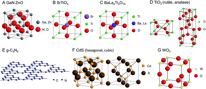 | ||
| Fig. 7 Geometrical structures of photocatalysts introduced in this review. (A) GaN:ZnO, (B) SrTiO3, (C) BaLa4Ti4O15, (D) TiO2, (E) g-C3N4, (F) CdS, and (G) WO3. | ||
| Semiconductor | Cocatalyst | Light source | Reactant solution | Ref. | ||
|---|---|---|---|---|---|---|
| Kinds | Loading amount | Size | ||||
| GaN:ZnO | Cr2O3/Rh NPs | 0.3–0.4 wt% | 1.9 ± 0.6 nm | 450 W Hg lamp (NaNO2 aq. filter) | Distilled water, 400 mL | 176 |
| GaN:ZnO | Cr2O3/Rh NPs (adsorption) | 2.5 wt% | 1.9 ± 0.6 nm | 450 W Hg lamp NaNO2 aq. filter) | Distilled water, 370–400 mL | 181 |
| Cr2O3/Rh NPs (photodeposition) | 1.0 wt% | >2–3 nm | ||||
| Cr2O3/Rh NPs (impregnation) | 0.25 wt% | >2–3 nm | ||||
| GaN:ZnO | Rh NPs | 0.1–0.3 wt% | 1.5 ± 0.3 nm | 450 W Hg lamp (NaNO2 aq. filter) | H2SO4 aq. (pH 4.5), 400 mL | 182 |
| 0.1–0.3 wt% | 3.8 ± 0.8 nm | |||||
| 0.1–0.3 wt% | 6.6 ± 1.1 nm | |||||
| GaN:ZnO | Cr2O3/Rh NPs (shell/core), Mn3O4 NPs | Rh: 0.75 wt%, Cr: 0.31 wt%, Mn: 0.05 wt% | Cr2O3/Rh: >2–3 nm, Mn3O4: 9.2 ± 0.4 nm | 300 W Xe lamp (λ > 420 nm) | Pure water, 100 mL | 184 |
| GaN:ZnO | Cr2O3/Rh NPs, Mn3O4 NPs | Rh: 0.75 wt%, Cr: 0.31 wt%, Mn3O4: 0.2 wt% | 300 W Xe lamp (λ > 420 nm) | H2O, 100 mL | 185 | |
| Cr2O3/Rh NPs, IrO2 NPs | Rh: 0.75 wt%, Cr: 0.31 wt%, IrO2: 0.3 wt% | |||||
| Cr2O3/Rh NPs, RuO2 NPs | Rh: 0.75 wt%, Cr: 0.31 wt%, RuO2: 0.2 wt% | |||||
| SrTiO3 | Cr2O3/Rh NPs, CoxMn3−xO4 NPs, (Co/(Co + Mn) ratio of 40 mol%) | Sum of Co and Mn: 0.05 wt%, Rh: 0.3 wt% | CoxMn3−xO4: 9.0 ± 0.8 nm | 300 W Xe lamp (λ > 300 nm) | H2O, 100 mL | 186 |
| Mn: 0.05 wt%, Rh: 0.3 wt% | 9.0 ± 0.5 nm | |||||
| BaLa4Ti4O15 | Au25 | 0.1 wt% | 1.2 ± 0.3 nm | 400 W Hg lamp | Distilled water, 350 mL | 187 |
| Au NPs | 0.5 wt% | 10–30 nm | ||||
| SrTiO3 | Au25 | 0.1 wt% | ∼1.2 nm | 400 W Hg lamp | Distilled water, 350 mL | 188 |
| Au NPs | 0.5 wt% | 9.5 ± 3.3 nm | ||||
| BaLa4Ti4O15 | Au10 | 0.1 wt% | 0.89 ± 0.19 nm | 400 W Hg lamp | Distilled water, 350 mL | 189 |
| Au15 | 0.1 wt% | 0.95 ± 0.21 nm | ||||
| Au18 | 0.1 wt% | 1.12 ± 0.22 nm | ||||
| Au25 | 0.1 wt% | 1.19 ± 0.28 nm | ||||
| Au39 | 0.1 wt% | 1.53 ± 0.26 nm | ||||
| BaLa4Ti4O15 | Au25 | 0.1 wt% | 1.1 ± 0.2 nm | 400 W Hg lamp | Distilled water, 350 mL | 190 |
| Cr2O3/Au25 | Cr: 0.5 wt%, Au: 0.1 wt% | 1.1 ± 0.3 nm | ||||
| BaLa4Ti4O15 | Au25 | 0.1 wt% | 1.24 ± 0.21 nm | 400 W Hg lamp | Distilled water, 350 mL | 202 |
| Au24Pd | 0.1 wt% | 1.11 ± 0.19 nm | ||||
| Au24Pt | 0.1 wt% | 1.11 ± 0.19 nm | ||||
| BaLa4Ti4O15 | Rh2−xCrxO3 NCs | Rh: 0.09 wt%, Cr: 0.10 wt% | 1.3 ± 0.3 nm | 400 W Hg lamp | Distilled water, 350 mL | 208 |
| Rh2−xCrxO3 NCs (impregnation) | Rh: 0.10 wt%, Cr: 0.15 wt% | 3.0 ± 2.3 nm | ||||
| TiO2 | PtO NCs | 0.5 wt% | 1.0 ± 0.3 | 300 W Xe lamp (λ > 300 nm) | Methanol aq. | 211 |
| Pt NCs | 1.0 wt% | 2.0 ± 0.5 nm | ||||
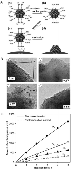 | ||
| Fig. 8 (A) Procedural flow of the proposed liquid-phase adsorption method: (a) Rh NPs stabilized by organic ligand molecules before cation exchange. (b) Stabilized Rh NPs after cation exchange. (c) Electrostatic adsorption on GaN:ZnO catalyst. (d) Removal of organic ligand. (B) TEM images of Rh NPs loaded on GaN:ZnO (a and b) before and (c and d) after coating with Cr2O3. (C) Time course of overall water splitting over Cr2O3/Rh/GaN:ZnO prepared by liquid-phase adsorption and photodeposition. Reaction conditions: catalyst, 0.15 g; distilled water, 400 mL; light source, high-pressure mercury lamp (450 W) via aqueous NaNO2 solution filter to cut UV light; reaction vessel, Pyrex inner-irradiation vessel. Almost the same amount of Rh (0.3–0.4 wt%) was loaded on each catalyst. Reproduced with permission from ref. 176. Copyright 2009 The Royal Society of Chemistry. | ||
In 2010, the same group further developed such research. In this study, various noble metals (Rh, Pd, and Pt) and metal oxides (NiOx, RuO2, and Rh2O3) were used as HER cocatalysts for GaN:ZnO photocatalysts.181 Both conventional methods (photodeposition and impregnation methods; Fig. 5A) and liquid-phase adsorption (Fig. 5B) were used to load NPs on the photocatalyst. A Cr2O3 shell was also formed on the cocatalyst surface. The highest activity was obtained when Rh was used as the core metal and the cocatalysts were loaded by liquid-phase adsorption. In the liquid-phase adsorption method, Rh cocatalysts with fine particle size can be loaded with high dispersion. Additionally, it is presumed that Rh cocatalysts loaded by liquid-phase adsorption have more metallic properties than those loaded by conventional methods. The photocatalyst with Rh NPs loaded by liquid-phase adsorption was considered to show high water-splitting activity because of these factors. This study also revealed that the morphology of the Cr2O3 shell depended on the valence state of the core Rh NPs and pH of the solution during the photodeposition of the Cr2O3 layer. Based on this knowledge, they formed a Cr2O3 shell with appropriate thickness on metallic Rh NPs at an appropriate pH (3.0–7.5) (Fig. 9), which yielded an efficient water-splitting photocatalyst.
 | ||
| Fig. 9 TEM images of Cr2O3/Rh NPs (shell/core)/GaN:ZnO. The core Rh NPs were loaded by (A) photodeposition, (B) impregnation, and (C) liquid-phase adsorption. Reproduced with permission from ref. 181. Copyright 2010 Wiley-VCH. | ||
In 2013, to further functionalize the Rh NP cocatalyst, Teranishi and colleagues investigated the correlation between the particle size of Rh NPs and water-splitting activity.182 In this study, Rh NPs were synthesized by polyol reduction using polyvinylpyrrolidone (PVP, Mw: 10![[thin space (1/6-em)]](https://www.rsc.org/images/entities/char_2009.gif) 000 or 40
000 or 40![[thin space (1/6-em)]](https://www.rsc.org/images/entities/char_2009.gif) 000) as a protective polymer. The effects of the pH and temperature of the reaction solution (ethylene glycol solution) on the particle size of the resulting PVP-protected Rh NPs (PVP–Rh NPs) were investigated. The nucleation rate of PVP–Rh NPs was controlled by the pH. The results obtained in this experiment were in good agreement with those of a theoretical calculation reported by Goia and co-workers.183 The reaction temperature also strongly affected the nucleation rate of PVP–Rh NPs. Based on these findings, they selected the appropriate pH and reaction temperature conditions and fabricated size-controlled PVP–Rh NPs (1.6 ± 0.3, 2.7 ± 0.3, and 5.1 ± 0.5 nm). Each sample of PVP–Rh NPs was stirred in ethanol with a GaN:ZnO photocatalyst to induce cocatalyst adsorption. Then, PVP was removed from the NPs by calcination at 673 K (Fig. 10A). A transmission electron microscope (TEM) image of the calcined sample revealed that although slight aggregation occurred on the GaN:ZnO photocatalyst, the Rh NPs still maintained their high monodispersity (1.5 ± 0.3, 3.8 ± 0.8, and 6.6 ± 1.1 nm). Then, a Cr2O3 layer was formed on the Rh NPs by photodeposition. Measurements of the water-splitting activity of the series of photocatalysts revealed that their water-splitting activity increased with decreasing cocatalyst size (Fig. 10B). They attributed this phenomenon to the following effects caused by the miniaturization of Rh NPs: (i) increased relative surface area of smaller Rh NPs; (ii) improved charge separation; and (iii) increased active sites for the HER.
000) as a protective polymer. The effects of the pH and temperature of the reaction solution (ethylene glycol solution) on the particle size of the resulting PVP-protected Rh NPs (PVP–Rh NPs) were investigated. The nucleation rate of PVP–Rh NPs was controlled by the pH. The results obtained in this experiment were in good agreement with those of a theoretical calculation reported by Goia and co-workers.183 The reaction temperature also strongly affected the nucleation rate of PVP–Rh NPs. Based on these findings, they selected the appropriate pH and reaction temperature conditions and fabricated size-controlled PVP–Rh NPs (1.6 ± 0.3, 2.7 ± 0.3, and 5.1 ± 0.5 nm). Each sample of PVP–Rh NPs was stirred in ethanol with a GaN:ZnO photocatalyst to induce cocatalyst adsorption. Then, PVP was removed from the NPs by calcination at 673 K (Fig. 10A). A transmission electron microscope (TEM) image of the calcined sample revealed that although slight aggregation occurred on the GaN:ZnO photocatalyst, the Rh NPs still maintained their high monodispersity (1.5 ± 0.3, 3.8 ± 0.8, and 6.6 ± 1.1 nm). Then, a Cr2O3 layer was formed on the Rh NPs by photodeposition. Measurements of the water-splitting activity of the series of photocatalysts revealed that their water-splitting activity increased with decreasing cocatalyst size (Fig. 10B). They attributed this phenomenon to the following effects caused by the miniaturization of Rh NPs: (i) increased relative surface area of smaller Rh NPs; (ii) improved charge separation; and (iii) increased active sites for the HER.
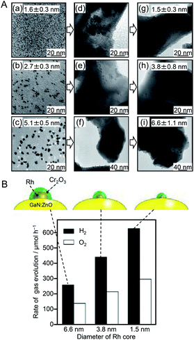 | ||
| Fig. 10 (A) TEM images of three kinds of PVP–Rh NPs (a–c) as-synthesized, (d–f) adsorbed on GaN:ZnO, and (g–i) loaded on GaN:ZnO after calcination. (B) Initial rates of H2 and O2 evolution over GaN:ZnO modified with different-sized Cr2O3/Rh (shell/core) NPs. Black and white symbols/bars indicate H2 and O2, respectively. Reaction conditions: catalyst, 0.15 g; H2SO4 aq. (pH 4.5), 400 mL; light source, high-pressure Hg lamp (450 W) through an NaNO2 aq. filter to cut UV light; reaction vessel, Pyrex inner-irradiation vessel. Reproduced with permission from ref. 183. Copyright 2013 American Chemical Society. | ||
The above examples demonstrated that control of the HER cocatalyst is an effective approach to improve the water-splitting activity of photocatalysts. In 2010, Domen et al.184 showed that co-loading of an OER cocatalyst with an HER cocatalyst led to even higher water-splitting activity. In this study, GaN:ZnO was used as the photocatalyst, Cr2O3/Rh (shell/core) NPs were employed as the HER cocatalyst, and Mn3O4 NPs as the OER cocatalyst (Fig. 11A). First, MnO NPs (9.2 ± 0.4 nm) were synthesized by a liquid-phase reduction method as a precursor of the OER cocatalyst. The MnO NPs were adsorbed on the GaN:ZnO photocatalyst and then calcined at 673 K to form Mn3O4 NPs. Next, Cr2O3/Rh NPs were loaded on the GaN:ZnO photocatalyst as an HER cocatalyst. TEM measurements confirmed that the two types of cocatalysts were loaded on the photocatalyst without covering each other (Fig. 11B). The water-splitting activities of the photocatalyst loaded with only Cr2O3/Rh NPs and that loaded with both Cr2O3/Rh NPs and Mn3O4 NPs were measured. The results revealed that: (i) an HER cocatalyst (Cr2O3/Rh) is necessary for H2 production; (ii) the photocatalyst co-loaded with both HER and OER cocatalysts (Cr2O3/Rh NPs and Mn3O4 NPs) showed higher activity than the photocatalyst loaded with only the HER cocatalyst (Cr2O3/Rh NPs) (Fig. 11C); and (iii) water-splitting activity depended on the loading amount of OER cocatalyst (Mn3O4 NPs). It was noted that such a co-loading method of both HER and OER cocatalysts is also applicable to cases where NPs composed of different metals are used as cocatalysts.
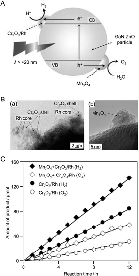 | ||
| Fig. 11 (A) Proposed reaction mechanism for visible light-driven overall water splitting on GaN:ZnO modified with Mn3O4 and Cr2O3/Rh (shell/core) NPs. CB: conduction band, VB: valence band, e−: electron, h+: hole. (B) TEM images of GaN:ZnO modified with Mn3O4 and Cr2O3/Rh (shell/core) NPs: (a) Cr2O3/Rh NPs, (b) Mn3O4 NPs. (C) Time courses of H2 and O2 evolution using modified GaN:ZnO catalysts under visible light (λ > 420 nm). Mn loading: 0.05 wt%. Reproduced with permission from ref. 184. Copyright 2010 Wiley-VCH. | ||
Thus, control of the cocatalyst is effective for both the HER and OER. However, in the early stages of research on cocatalysts, it was unclear whether the HER or OER was the rate-limiting step in the water-splitting reaction. In 2014, Domen and colleagues conducted a study to determine the rate-limiting step of water splitting.185 In this study, GaN:ZnO was again used as the photocatalyst, along with Mn3O4 NPs, RuO2 NPs, or IrO2 NPs as the OER cocatalyst and Cr2O3/Rh NPs as the HER cocatalyst (Fig. 12A). Evaluation of the water-splitting activity of each photocatalyst revealed that their activities were almost independent of the type of OER cocatalyst (Fig. 12B). Also, the amount of loaded OER cocatalyst to achieve high activity was much smaller than that of the HER cocatalyst. These results suggested that the HER was the rate-limiting step of water splitting by the photocatalyst used in this study. Based on these findings, they also optimized the HER cocatalyst. Specifically, GaN:ZnO photocatalysts co-loaded with RuO2 NPs and Cr2O3/Rh NPs were fabricated by both liquid-phase adsorption of Rh NPs (3.3 ± 0.8 nm) and photodeposition of Rh NPs. They measured the water-splitting activities of both types of Cr2O3/Rh NPs + RuO2 NPs/GaN:ZnO photocatalysts. The photocatalyst with Cr2O3/Rh NP cocatalyst loaded using liquid-phase adsorption showed higher water-splitting activity than that with the cocatalyst NPs loaded using the photodeposition method. These results indicate that controlling the HER cocatalyst is very important for enhancing the water-splitting activity of the GaN:ZnO photocatalyst.
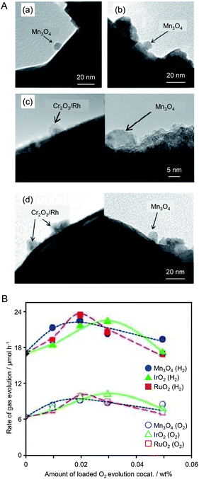 | ||
| Fig. 12 (A) TEM images of (a and b) Mn3O4 NPs/GaN:ZnO and (c and d) Cr2O3/Rh NPs + Mn3O4 NPs/GaN:ZnO (a and c) before and (b and d) after calcination of the photocatalyst at 873 K. (B) Photocatalytic activity of GaN:ZnO co-loaded with different OER cocatalysts and Cr2O3/Rh NPs. Circles, triangles, and squares indicate the loading of Mn3O4, IrO2, and RuO2 NPs, respectively. Closed and open symbols denote H2 and O2, respectively. Reproduced with permission from ref. 185. Copyright 2014 Wiley-VCH. | ||
When SrTiO3 was used as the photocatalyst instead of GaN:ZnO solid solution, control of the OER cocatalyst also proved effective to improve water-splitting activity. In 2018, Teranishi et al.186 synthesized CoxMn3−xO4 NPs (Co/(Co + Mn) = 0–40 mol%) by doping Co into Mn3O4 NPs using a liquid-phase reduction method (Fig. 13A). The obtained CoxMn3−xO4 NPs were loaded on an SrTiO3 photocatalyst as OER cocatalysts after Cr2O3/Rh NPs were loaded as HER cocatalysts (Fig. 13B). TEM analysis confirmed that the particle size (∼9 nm) of the CoxMn3−xO4 NPs was maintained after loading on SrTiO3. The water-splitting activity of the photocatalyst increased with the amount of Co of CoxMn3−xO4. The photocatalyst loaded with CoxMn3−xO4 NPs with a Co/(Co + Mn) ratio of 40 mol% showed water-splitting activity that was 1.8 times higher than that of the catalyst loaded with Mn3O4 NPs (Fig. 13B and C). To investigate the origin of such activity enhancement, they examined the electrocatalytic activity of CoxMn3−xO4-loaded BiVO4 photocatalysts in the OER. The results revealed that the efficiency of hole transfer from the photocatalyst to the cocatalyst was not increased by Co doping. Based on these results, they attributed the improvement of water-splitting activity to the increased OER activity on the cocatalyst surface induced by Co doping.
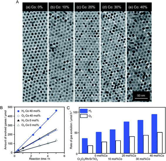 | ||
| Fig. 13 (A) TEM images of CoxMn1−xO NPs (∼9 nm) with different Co ratios of (a) 0, (b) 10, (c) 20, (d) 30, and (e) 40 mol% Co. (B) Time course of overall water splitting using Cr2O3/Rh + CoxMn3−xO4/SrTiO3 under light irradiation (λ > 300 nm). The amount of loaded CoxMn3−xO4 was 0.05 wt% calculated from the sum of Co and Mn. (C) Photocatalytic activities of Cr2O3/Rh/SrTiO3 and Cr2O3/Rh + CoxMn3−xO4/SrTiO3 in overall water splitting. Co ratios were 0, 10, 20, 30, and 40 mol% Co. The loading amount was 0.05 wt%, as calculated from the sum of Co and Mn. Reaction conditions: catalyst, 0.1 g; aqueous solution, 100 mL; light source, 300 W Xe lamp (λ > 300 nm); reaction vessel, Pyrex top-irradiation vessel. Reproduced with permission from ref. 186. Copyright 2018 The Royal Society of Chemistry. | ||
Since 2013, Negishi's group has published several papers on the use of atomically precise metal NCs as precursors of HER cocatalysts. First, in 2013, they succeeded in loading Au25 NC with high dispersion on the surface of a UV light-responsive BaLa4Ti4O15 photocatalyst.187 In this experiment, first, Au25 NC protected by glutathionate (SG), Au25(SG)18, were synthesized precisely. Then, Au25(SG)18 was adsorbed on BaLa4Ti4O15. Thereafter, the ligands of Au25(SG)18 were removed by calcination, providing Au25 NC-loaded BaLa4Ti4O15 (denoted as Au25 NC/BaLa4Ti4O15). Various evaluations of Au25 NC/BaLa4Ti4O15 confirmed that the Au25 NCs were well dispersed on BaLa4Ti4O15 (Fig. 14A), and that most of the ligands were removed by calcination. The water-splitting activity of Au25 NC/BaLa4Ti4O15 was 2.6 times higher than that of BaLa4Ti4O15 loaded with Au NPs with a diameter of 10–30 nm by the photodeposition method (this sample is denoted as Au NPs/BaLa4Ti4O15) (Fig. 14B). These results indicate that the use of the fine Au NC cocatalyst is indeed effective for enhancing the water-splitting activity of the photocatalyst. In another paper, Negishi's group reported that such an improvement in water-splitting activity caused by the ultra-miniaturization of the Au cocatalyst also occurred when SrTiO3 was used as a photocatalyst.188 This result demonstrates that loading the fine Au NC cocatalyst (more widely metal NCs120) is also possible for the other photocatalysts when using SG as a ligand of NCs.
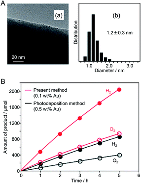 | ||
| Fig. 14 (A) (a) TEM image and (b) size distribution of adsorbed NCs estimated from the TEM image of Au25 NC/BaLa4Ti4O15. (B) Time course of water splitting over Au25 NC/BaLa4Ti4O15 photocatalyst (0.1 wt% Au) prepared by the present method (red) and Au NPs/BaLa4Ti4O15 photocatalyst (0.5 wt% Au) prepared by the conventional photodeposition method (black). Reaction conditions: photocatalyst, 0.5 g; distilled water, 350 mL; light source, high-pressure Hg lamp (400 W), inner irradiation cell made of quartz. Reproduced with permission from ref. 187. Copyright 2013 The Royal Society of Chemistry. | ||
In 2015, Negishi's group synthesized a series of Aun(SG)m NCs (n = 10, 15, 18, 25, and 39) with controlled numbers of constituent atoms with atomic precision and used the NCs as cocatalyst precursors.189 They investigated the correlation between cocatalyst size and water-splitting activity. In this study, when Aun(SG)m NCs (n = 22, 29, and 33) were used as precursors, the aggregation of Au NCs on the photocatalyst surface occurred during adsorption or calcination. It has been revealed that Aun(SG)m NCs (n = 22, 29, and 33) are metastable species which are kinetically trapped during the NC formation and decompose (release of SG or Au-SG oligomers) in aqueous solution in a shorter time when compared with Aun(SG)m NCs (n = 10, 15, 18, 25, and 39).81 It was that for Aun(SG)m NCs (n = 22, 29, and 33), part of the Aun(SG)m NCs dissociate during the stirring process and Au-SG oligomers, formed from the dissociated products, adsorb conjunctively with the Aun(SG)m NCs. The existence of such Au-SG oligomers was considered to promote cohesion of clusters on BaLa4Ti4O15 during calcination. These results indicate that it is difficult to load Aun(SG)m NCs that are unstable in solution on the BaLa4Ti4O15 photocatalyst while maintaining the number of constituent atoms of NCs. This means that it is essential to use metal NCs that are stable in solution as a cocatalyst precursor to achieve precise loading of metal NCs (Fig. 15A). Then, the correlation between cocatalyst size and water-splitting activity was investigated by evaluating the water-splitting activities of Aun NCs/BaLa4Ti4O15 photocatalysts prepared using Aun(SG)m NCs (n = 10, 15, 18, 25, and 39), which are stable in solution,81 as cocatalyst precursors. It was found that the water-splitting activity increased as the size of the Aun NC cocatalyst decreased (Fig. 15B). Because the increase in activity with cocatalyst size decrease was modest, it was considered that the change in activity between the catalysts was mainly caused by the change in the proportion of Au NC surface atoms with miniaturization (i.e., Au atoms that react with hydrogen). Conversely, the difference in water-splitting activity between Aun NCs/BaLa4Ti4O15 and Au NPs/BaLa4Ti4O15 could not be fully explained by the difference in the number of surface atoms (Fig. 15B). From various analyses, it was found that the activity per Au atom on the surface of Au10 NCs/BaLa4Ti4O15 was only about 15–25% of that of Au NPs/BaLa4Ti4O15. Therefore, it was concluded that the main factor behind the improved activity caused by the ultra-miniaturization of the HER cocatalyst (Fig. 15B) was the increase of the number of surface Au atoms with an efficiency exceeding the decrease in activity per Au atom.
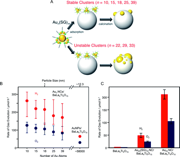 | ||
| Fig. 15 (A) Schematic of the size control of Aun NCs loaded on photocatalysts. (B) Effect of cluster size on water-splitting activity studied using Aun NCs/BaLa4Ti4O15 and Au NPs/BaLa4Ti4O15 photocatalysts. The average values obtained from four measurements are plotted herein. (C) Comparison of the photocatalytic activities of BaLa4Ti4O15, Au25(SG)18 NC/BaLa4Ti4O15, and Au25 NC/BaLa4Ti4O15. Reproduced with permission from ref. 189. Copyright 2015 American Chemical Society. | ||
In the same paper, Negishi et al.189 also examined the importance of ligand removal in such composite systems. Multiple studies have reported that for composites composed of Aun(SG)m NCs and semiconductor photocatalysts, electron transfer occurs even when the ligands are present.139 Indeed, Au25(SG)18 NC/BaLa4Ti4O15 that had not been calcined showed higher water-splitting activity than that of BaLa4Ti4O15 without the NC cocatalysts (Fig. 15C). This indicates that electron transfer occurs between the Au25(SG)18 NC and BaLa4Ti4O15 without removing the ligands, and thus Au25(SG)18 NC also function as a cocatalyst. However, the water-splitting activity of Au25(SG)18 NC/BaLa4Ti4O15 was about 23% of that of Au25 NC/BaLa4Ti4O15 with the ligands removed (Fig. 15C). This means that the presence of the ligands lowers the efficiency of the electron transfer between Au25 NC and BaLa4Ti4O15 or decreases the activity of individual Au atoms. These results clarified that ligand removal by calcination is very important to obtain composite photocatalysts with high water-splitting activity.
In this way, the use of the fine metal NCs as a cocatalyst is effective to improve the water-splitting activity of photocatalysts. However, the ORR, which is a reverse reaction of water splitting, proceeds simultaneously with the HER on the Au25 NC surface.188 Therefore, to more effectively utilize the high surface area unique to fine metal NCs and thereby obtain highly active photocatalysts, it is necessary to form a shell that suppresses the ORR on the surface of Au25 NC. In 2018, Kurashige and co-workers attempted to form a Cr2O3 shell on Au25 NC.190 In the case of the Cr2O3/Rh NPs described in Section 4.1, the Cr2O3 shell was formed by photodeposition. However, in the case of Au25 NC/BaLa4Ti4O15, light irradiation induced the aggregation of Au25 NC on BaLa4Ti4O15. Therefore, it was difficult to use photodeposition to form a Cr2O3 shell on Au25 NC loaded on BaLa4Ti4O15 while maintaining the size of the NCs.
Surface science research has revealed that when a metal oxide supporting metal NPs is heated under H2 or O2 atmosphere, a strong metal–support interaction (SMSI) is induced and thereby an oxide film is formed on the metal NPs.191–194 Kurashige et al. attempted to use such an SMSI effect to form a Cr2O3 shell on the Au25 NC surface (Fig. 16A). Specifically, a Cr2O3 layer was deposited on BaLa4Ti4O15 by photodeposition to form Cr2O3/BaLa4Ti4O15 before loading Au25 NC (Fig. 16A). Then, Au25(SG)18 was adsorbed on Cr2O3/BaLa4Ti4O15, and both ligand removal and surface protection by the SMSI effect were achieved by calcination. A TEM image of the photocatalyst after calcination showed the formation of a thin film with a thickness of about 0.7–0.9 nm around particles with a diameter of about 1 nm (Fig. 16B). This indicates that the Au25 NC were covered with a chromium oxide layer during calcination (Fig. 16A). Some of the chromium oxide layer of Cr2O3/Au25 NC/BaLa4Ti4O15 was oxidized to a highly oxidized state during calcination. The photocatalyst was irradiated with UV light to reduce the highly oxidized chromium oxide to Cr2O3 and thereby the desired Cr2O3/Au25 NC/BaLa4Ti4O15 was obtained. The water-splitting activity of Cr2O3/Au25 NC/BaLa4Ti4O15 was about 19 time higher than that of Au25 NC/BaLa4Ti4O15 (Fig. 16C). This indicates that the formation of the Cr2O3 shell is effective at suppressing the ORR on the surface of the Au NC cocatalyst. The formation of such a Cr2O3 shell also suppressed aggregation of the cocatalyst during light irradiation. This indicates that the Cr2O3 shell formed by the method established by Kurashige and colleagues improves not only the water-splitting activity but also the stability of the cocatalyst on the photocatalyst surface.
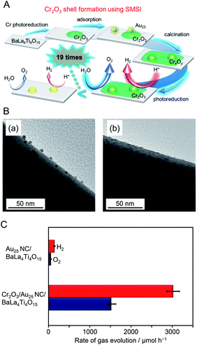 | ||
| Fig. 16 (A) Schematic of the preparation of Cr2O3/Au25 NC/BaLa4Ti4O15. (B) TEM images of (a) Au25 NC/BaLa4Ti4O15 and (b) Cr2O3/Au25 NC/BaLa4Ti4O15 after UV irradiation for 10 h. (C) Comparison of rates of H2 and O2 evolution by photocatalytic water splitting over Au25 NC/BaLa4Ti4O15 and Cr2O3/Au25 NC/BaLa4Ti4O15 (0.5 wt% Cr). Averages of values obtained from several experiments are shown. Reproduced with permission from ref. 190. Copyright 2018 American Chemical Society. | ||
It is expected that photocatalysts with higher water-splitting activity could be realized by heteroatom doping of fine Au NC cocatalysts. In previous studies on the effect of heteroatom doping on photocatalyst activity, experiments have been conducted using photocatalysts with distributions of the particle size and doping ratio (chemical composition) of the cocatalysts.195–201 To obtain a deep understanding of the effect of heteroatom doping on photocatalytic activity and thereby establish clear design guidelines for photocatalyst activation, it is essential to study composite photocatalysts on which the cocatalysts have strictly controlled chemical composition. Recently, Kurashige et al.202 attempted to use Au24Pd and Au24Pt NCs, in which one Au atom of the Au25 NC is substituted with Pd or Pt, as an HER cocatalyst. Au24Pd(SR)18 and Au24Pt(SR)18 NCs can be precisely synthesized only when a hydrophobic ligand is used.202 However, the metal NCs protected by hydrophobic ligands could not strongly interact with the hydrophilic surface of BaLa4Ti4O15, which led to poor adsorption on the photocatalyst. Then, they replaced some of the ligands of Au24Pd(SR)18 and Au24Pt(SR)18 NCs with a hydrophilic ligand, which allowed them to adsorb on BaLa4Ti4O15 at a high adsorption rate (Fig. 17A). The ligands on the NC surface were removed by calcination (Fig. 17A).
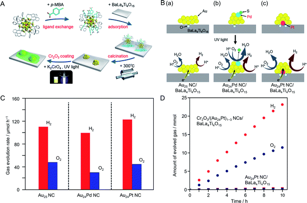 | ||
| Fig. 17 (A) Schematic of the experimental procedure. (B) Proposed structures of Au24M NC/BaLa4Ti4O15 with M of (a) Au, (b) Pd, and (c) Pt before (upper) and during (lower) the water-splitting reaction. (C) Rates of photocatalytic evolution of H2 and O2 by water splitting over Au24M NC/BaLa4Ti4O15 with M of Au, Pd, and Pt. (D) Time course of water splitting over Cr2O3/(Au24Pt)1–3 NCs/BaLa4Ti4O15 and Au24Pt NC/BaLa4Ti4O15. Reproduced with permission from ref. 202. Copyright 2019 American Chemical Society. | ||
Investigation of the photocatalyst loaded with cocatalyst NCs controlled with atomic precision revealed the following three points about the heteroatom doping of the Au cocatalyst: (i) the Pd atom was located on the surface of the metal NC and the Pt atom was located at the interface between the metal NC and photocatalyst (Fig. 17B); (ii) Pd doping induced a decrease of water-splitting activity and Pt doping caused water-splitting activity to increase (Fig. 17C); (iii) these opposite effects of Pd and Pt heteroatom doping are strongly related to the location of the doped heteroatom (Fig. 17B). The results also showed that combining Pt doping and surface protection of the cocatalyst with a Cr2O3 shell increased the activity and stability of the photocatalysts to a greater extent than only Pt doping (Fig. 17D).
In the above series of research, Au was used as the base element of the NC cocatalyst. It has been predicted that Rh has higher catalytic activity than Au with respect to the HER based on volcano plots for hydrogen adsorption and desorption.203 Therefore, it is expected that a highly active water-splitting photocatalyst could be obtained by loading Rh and Cr oxide NPs/NCs as an HER cocatalyst on the photocatalyst. Indeed, Domen and co-workers reported that a photocatalyst loaded with Rh(III)–Cr(III) mixed oxide NPs (Rh2−xCrxO3; particle size = 10–30 nm) showed higher water-splitting activity than that of photocatalysts loaded with metal NPs composed of other elements.204–207 If ultrafine Rh2−xCrxO3 NCs could be loaded on the photocatalyst as an HER cocatalyst, it might be possible to activate the photocatalyst further. Very recently, Kurashige et al.208 attempted to load fine Rh2−xCrxO3 NCs as an HER cocatalyst on BaLa4Ti4O15 by modifying the method shown in Fig. 16A. Unfortunately, the precise synthesis of Rh2−xCrxO3 NCs has not been reported. Therefore, in this experiment, a complex containing Rh2(SG)2 as the main component was used as a precursor. First, Rh2(SG)2 was adsorbed on BaLa4Ti4O15 covered with a Cr2O3 film, and then the resulting photocatalyst was calcined. These operations resulted in loading of Rh2−xCrxO3 NCs on the photocatalyst (Fig. 18A). Various structural analyses showed that about six Rh2(SG)2 complexes aggregated during adsorption and that the Rh and Cr2O3 films formed solid solutions during calcination (Fig. 18B). Monodisperse Rh2−xCrxO3 NCs with a particle size of 1.3 ± 0.3 nm were loaded on BaLa4Ti4O15 by this method (Fig. 18C). The obtained photocatalyst exhibited an apparent quantum yield of 16% under 270 nm excitation, which is the highest achieved for BaLa4Ti4O15 to date (Fig. 18D). These results indicate that loading Rh2−xCrxO3 NCs by this method is an effective approach to improve the water-splitting activity of the BaLa4Ti4O15 photocatalyst. In principle, this method is applicable to the other photocatalysts. Rh2−xCrxO3 has already proved a useful cocatalyst in many water-splitting photocatalysts.204–207,209,210 In the future, it is expected that high quantum yields can be achieved for many water-splitting photocatalysts using this technique.
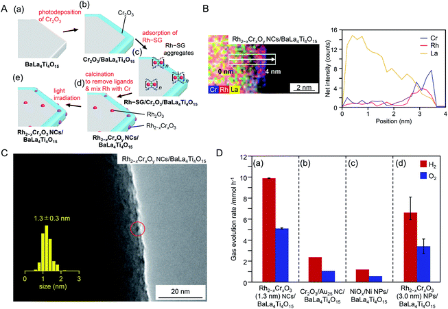 | ||
| Fig. 18 (A) Schematic of the experimental procedure to form (a) BaLa4Ti4O15, (b) Cr2O3/BaLa4Ti4O15, (c) Rh–SG/Cr2O3/BaLa4Ti4O15, (d) Rh2−xCrxOy NCs/BaLa4Ti4O15, and (e) Rh2−xCrxO3 NCs/BaLa4Ti4O15. Rh2−xCrxOy NCs indicates Rh2−xCrxO3 NCs including highly oxidized Cr (>+3). (B) Elemental mapping line analysis by STEM measurements for Rh2−xCrxOy NCs/BaLa4Ti4O15. (C) TEM image of Rh2−xCrxOy NCs/BaLa4Ti4O15. The red circles indicate the Rh2−xCrxO3 NCs. (D) Comparison of gas evolution rates over different photocatalysts (a) Rh2−xCrxO3 (1.3 nm) NCs/BaLa4Ti4O15 (0.09 wt% Rh and 0.10 wt% Cr), (b) Cr2O3/Au25 NC/BaLa4Ti4O15 (0.10 wt% Au and 0.50 wt% Cr), (c) NiOx/Ni NPs/BaLa4Ti4O15 (0.50 wt% Ni), and (d) Rh2−xCrxO3 (3.0 nm) NPs/BaLa4Ti4O15 (0.10 wt% Rh and 0.15 wt% Cr). Reproduced with permission from ref. 208. Copyright 2020 Wiley-VCH. | ||
In the above research, the Cr2O3 shell on the cocatalyst surface suppressed the ORR, which is one of the reverse reactions of water splitting. When Pt NPs were used as a cocatalyst, the hydrogen oxidation reaction (HOR), which is also a reverse reaction of water splitting, proceeds simultaneously with the HER. In 2013, Wang and colleagues showed that platinum oxide (PtO) NCs could suppress the HOR.211 In their study, UV-responsive TiO2 was used as the photocatalyst and PtO or Pt NCs were used as the HER cocatalyst. To load PtO NCs on the photocatalyst, TiO2{001} nanosheets and poly(methacrylic acid) were dispersed in an aqueous solution containing chloroplatinic acid. Fine PtO NCs were loaded on TiO2 by injecting an aqueous solution of NaBH4 into the vigorously stirring reaction solution to form PtO NCs/TiO2.212 The polymer in PtO NCs/TiO2 was removed by washing the sample with ethanol several times. Pt NCs were loaded on TiO2 to form Pt NCs/TiO2 using the same mixing method without polymer. Scanning TEM (STEM) images revealed that the loaded PtO NCs (Fig. 19A) and Pt NCs had particle diameters of 1.0 ± 0.3 and 2.0 ± 0.5 nm, respectively. The HER and HOR activities of the obtained photocatalysts were evaluated (Fig. 19B). It was revealed that PtO NCs/TiO2 showed high HER activity and suppressed HOR activity. Similar HOR suppression was not observed for Pt NCs/TiO2 (Fig. 19B). To clarify the reasons for this difference, they conducted density functional theory (DFT) calculations using Pt8O8/TiO2 and Pt12/TiO2 as models (Fig. 19C). The results revealed that the reaction between H and O occurred easily on Pt12/TiO2 because the adsorption energies of Pt–H and Pt–O were large. Conversely, for Pt8O8/TiO2, it was shown that it was difficult for the HOR to occur because the adsorption energies of H and O were smaller than those of Pt12/TiO2 (Fig. 19D). In this study, because PtO NCs were synthesized and loaded on TiO2 in a single reaction system, it is difficult to judge whether size-controlled PtO NCs were synthesized and subsequently loaded on TiO2 or the size of PtO NCs loaded on TiO2 was controlled by the coexistence of polymer. In addition, the number of constituent atoms of the PtO and Pt NCs was not controlled with atomic precision. However, this study is important because it revealed a different approach to inhibit reverse reactions of water splitting.
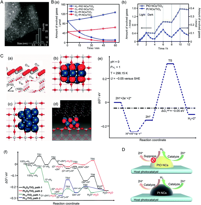 | ||
| Fig. 19 (A) Representative STEM image clearly showing isolated three-dimensional PtO NCs (bright spots). (B) (a) Reaction time profiles of the HOR with H2 and O2 on PtO NCs/TiO2 and Pt NCs/TiO2 photocatalysts under UV-visible light irradiation (λ > 300 nm). (b) H2 evolution and undesirable oxidation in methanol aqueous solution during three cycles of light irradiation (λ > 300 nm, 2 h) followed by dark conditions (light off, 2 h) on PtO NCs/TiO2 and Pt NCs/TiO2. (C) (a) Structure of the anatase TiO2(001) surface. (b) Optimized Pt8O8 NCs adsorbed on the TiO2(001) surface (Pt8O8 NCs/TiO2) and (c) optimized Pt12 NCs/TiO2. (d) Transition state structure of H*–H* coupling on Pt8O8 NCs/TiO2 in the liquid phase, which contained two layers of water molecules above the Pt8O8 NCs. (e) Standard Gibbs free energy profile of the HER in aqueous solution on Pt8O8 NCs/TiO2. (f) Standard Gibbs free energy profile of H2 reacting with O2 on Pt8O8 NCs/TiO2 and Pt12 NCs/TiO2 surfaces in the gas phase. Dark blue, gray, white, and red balls represent Pt, Ti, H, and O atoms, respectively. (D) Both PtO NCs and m-Pt NCs cocatalysts acted as H2 evolution sites on the host photocatalyst surface. The undesirable H2 reverse-reaction was suppressed by the PtO NC cocatalyst but facilitated by the Pt NC cocatalyst. Reproduced with permission from ref. 211. Copyright 2013 Nature Publishing Group. | ||
In this way, the use of metal NCs with controlled fine size as a cocatalyst can induce an increase in water-splitting activity because of their large surface area. Such precisely controlled cocatalysts make it possible to obtain a deep understanding of the effects of cocatalyst size and heteroatom doping on photocatalyst activity, as well as the origins of these effects. The findings obtained from these studies are expected to lead to clear design guidelines for the development of highly active and stable water-splitting photocatalysts.
4.2. Application in H2 evolution
In addition to the studies on overall water splitting described in Section 4.1, many reports on the improvement of the activity of each half reaction of water splitting (HER and OER) by controlling the cocatalyst have appeared recently. In the following subsections, we focus on research of HER using controlled colloidal metal NPs/NCs and introduce some typical research examples. The photocatalysts used in these studies are also summarized in Fig. 7. The materials and conditions used in the experiments are summarized in Table 2.| Semiconductor | Cocatalyst | Light source | Reactant solution | Ref. | ||
|---|---|---|---|---|---|---|
| Kinds | Loading amount | Size | ||||
| TiO2 | Pt NPs {100} | 0.5 wt% | 4.7 ± 1.6 nm | 300 W Xe lamp (λ > 420 nm) | 15% (v/v) TEOA aq. with Eosin Y | 214 |
| Pt NPs {100/111} | 0.5 wt% | 6.0 ± 1.5 nm | ||||
| Pt NPs {111} | 0.5 wt% | 6.5 ± 2.0 nm | ||||
| TiO2 | Au NPs {100} | 0.5 wt% | 9.2 nm | 300 W Xe lamp (λ > 420 nm) | 15% (v/v) TEOA aq. with Eosin Y | 215 |
| Au NPs {100/111} | 0.5 wt% | 9.5 nm | ||||
| Au NPs {111} | 0.5 wt% | 8.5 nm | ||||
| g-C3N4 | Rh NPs | 0.25 wt% | 4.1 ± 0.8 nm | Xe lamp (420 < λ < 630 nm) | 10% methanol aq. | 216 |
| 0.23 wt% | 5.9 ± 1.1 nm | |||||
| 0.34 wt% | 7.8 ± 1.4 nm | |||||
| 0.27 wt% | 9.1 ± 1.7 nm | |||||
| g-C3N4/Al2Si2O5(OH)4 | Ni(OH)2 NPs | 1 wt% | <100 nm | 300 W Xe lamp (λ > 400 nm) | 10 vol% methanol aq. | 217 |
| CdS | Pt–Pd NPs {100} (Pt![[thin space (1/6-em)]](https://www.rsc.org/images/entities/char_2009.gif) : :![[thin space (1/6-em)]](https://www.rsc.org/images/entities/char_2009.gif) Pd = 2 Pd = 2![[thin space (1/6-em)]](https://www.rsc.org/images/entities/char_2009.gif) : :![[thin space (1/6-em)]](https://www.rsc.org/images/entities/char_2009.gif) 1) 1) |
0.5 wt% | 7.9 nm | 300 W Xe lamp (λ > 420 nm) | 1.0 M (NH4)2SO3 aq. | 218 |
Pt–Pd NPs {111} (Pt![[thin space (1/6-em)]](https://www.rsc.org/images/entities/char_2009.gif) : :![[thin space (1/6-em)]](https://www.rsc.org/images/entities/char_2009.gif) Pd = 2 Pd = 2![[thin space (1/6-em)]](https://www.rsc.org/images/entities/char_2009.gif) : :![[thin space (1/6-em)]](https://www.rsc.org/images/entities/char_2009.gif) 1) 1) |
0.5 wt% | 5.2 nm | ||||
| TiO2 nanotubes | CuO NPs (A–C) | Cu/Ti ratio: 9 atom% | 3 nm | 400 W Hg lamp | 10 vol% methanol aq. | 219 |
| CuO NPs (WI) | Cu/Ti ratio: 9.6 atom% | |||||
| CdS | Pt NCs | 1 wt% | 0.9 ± 0.1 nm | 300 W Xe lamp (λ > 420 nm) | Na2S and Na2SO3 aq. | 220 |
| Pt NPs | 1 wt% | 5 nm | ||||
| g-C3N4 | Ag25 | 0.2 wt% | 1.5 ± 0.25 nm | Visible light (λ > 420 nm) | 10 vol% TEOA aq. | 221 |
| PtAg24 | 0.2 wt% | 1.5 ± 0.25 nm | ||||
| g-C3N4 | Au25 | 0.18 wt% | Visible light (λ > 420 nm) | 10 vol% TEOA aq. | 224 | |
| 0.49 wt% | ||||||
| 0.96 wt% | ||||||
| ZIF-8/TiO2 | Au25 Re complex | 1.2 nm | 300 W Xe lamp (λ > 420 nm) | H2O (1 mL), TEOA (1 mL), acetonitrile (4 mL), [Ru(bpy)3]Cl2·6H2O (10.0 μmol) | 225 | |
| Au NPs Re complex | ∼10 nm | |||||
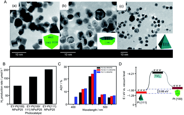 | ||
| Fig. 20 (A) TEM images of (a) Pt{100}, (b) Pt{100/111}, and (c) Pt{111} NPs, respectively. The insets are schematics of the corresponding Pt NPs. (B) H2 evolution rates of Eosin Y (4.0 × 10⁻⁴ M)-sensitized Pt{100} NPs/TiO2, Pt{100/111} NPs/TiO2, and Pt{111} NPs/TiO2 photocatalysts from 100 mL of 15% (v/v) TEOA aqueous solution under visible light irradiation (λ > 420 nm). (C) Apparent quantum yield of the HER for the above three photocatalysts. Light source: 300 W Xe lamp with either a cut-off filter of 420 nm or band-pass filter. (D) Schematic of the different energy levels of Pt{100} (solid curve) and Pt{111} (dotted curve) facets. Reproduced with permission from ref. 214. Copyright 2013 American Chemical Society. | ||
In 2014, Lu's group also conducted similar research using Au NPs.215 In this experiment, first, cubic-shaped Au{100} NPs, truncated cubic-shaped Au{100/111} NPs, and octahedral-shaped Au{111} NPs were synthesized by liquid-phase reduction. Each type of Au NPs was adsorbed on TiO2 by stirring the Au NPs and TiO2 in water. A series of photocatalytic HER activity measurements revealed that the photocatalyst using Au{111} NPs as a cocatalyst (denoted as Au{111} NPs/TiO2) possessed the highest HER activity of the samples. Photoluminescence measurements and model calculations indicated that Au{111} NPs/TiO2 showed high HER activity because of the same reasons as Pt{111} NPs/TiO2.
As shown in the above examples, to control the cocatalyst, it is very important to select an appropriate element, refine the particle size, improve the dispersibility, form an alloy, form a shell to suppress reverse reactions of water splitting, and control shell thickness. In 2014, Hensen et al.216 showed that the valence state of the Rh NP surface had also a large effect on the HER activity of a complex system composed of Rh NPs and visible light-responsive g-C3N4 photocatalyst. They synthesized PVP–Rh NPs with sizes of 4.1 ± 0.8, 5.9 ± 1.1, 7.8 ± 1.4, and 9.1 ± 1.7 nm and adsorbed them on g-C3N4 to form PVP–Rh NPs/g-C3N4 (Fig. 21A). Then, PVP on the Rh NP surface was removed by ozone oxidation. In general, removal of the protective ligand induces an increase in HER activity. However, the Rh NPs/g-C3N4 samples obtained after ozone oxidation showed lower HER activity than PVP–Rh NPs/g-C3N4 (Fig. 21B). When the samples after ozone oxidation were calcined under H2 flow, their activity increased. These results indicated that the activity decreased when the surface of the Rh NP cocatalyst was oxidized by ozone, whereas the activity increased when the Rh NPs were reduced by calcination under flowing H2. Thus, it was clarified that the high metallicity of the cocatalyst surface is important to improve the HER activity of Rh NPs/g-C3N4 photocatalysts.
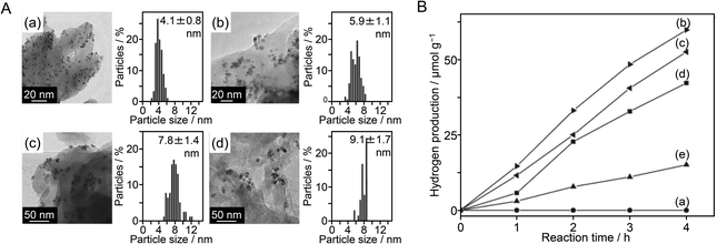 | ||
| Fig. 21 (A) Representative TEM images and particle size distributions of (a) PVP–Rh (4.1 nm) NPs/g-C3N4, (b) PVP–Rh (5.9 nm) NPs/g-C3N4, (c) PVP–Rh (7.8 nm) NPs/g-C3N4 and (d) PVP–Rh (9.1 nm) NPs/g-C3N4. (B) Photocatalytic hydrogen production rates as a function of time for (a) pure g-C3N4, (b) PVP–Rh (4.1 nm) NPs/g-C3N4, (c) PVP–Rh (5.9 nm) NPs/g-C3N4, (d) PVP–Rh (7.8 nm) NPs/g-C3N4 and (e) PVP–Rh (9.1 nm) NPs/g-C3N4. Reproduced with permission from ref. 216. Copyright 2014 Elsevier Ltd. | ||
Recently, Hojamberdiev et al.217 also studied the HER activity of g-C3N4. In their study, Ni(OH)2, which is a relatively inexpensive HER cocatalyst, and halloysite (Al2Si2O5(OH)4) as a hole trapping agent were co-loaded on g-C3N4 (Fig. 22A). The HER activity of the obtained photocatalyst was measured in an aqueous solution containing 10 vol% methanol as a sacrificial agent. The HER activity of the catalyst loaded with 1 wt% Ni(OH)2 was about 40 times higher than that of g-C3N4 alone. This indicates that co-loading Ni(OH)2 and halloysite is an effective approach to improve the HER activity of g-C3N4. Ni(OH)2 loaded on a photocatalyst promoted charge separation by capturing photoexcited electrons, and the negative charges on the halloysite surface captured holes generated by photoexcitation. This behavior led to the extremely high HER activity of the catalyst co-loaded with Ni(OH)2 and halloysite (Fig. 22B). A model calculation was performed to evaluate the adsorption affinity of water and methanol molecules on the catalyst surface. The results showed that the combination of g-C3N4, halloysite, and Ni(OH)2 promoted the adsorption of water and methanol on the cocatalyst surface.
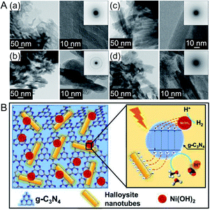 | ||
| Fig. 22 (A) TEM and high-resolution TEM images of (a) g-C3N4, (b) Ni(OH)2, (c) halloysite, and (d) Ni(OH)2/g-C3N4 halloysite nanocomposites prepared with 1 wt% Ni(OH)2. (B) Schematic representation of the separation and transfer of photogenerated charge carriers involved in photocatalytic H2 evolution over the developed nanocomposite. Reproduced with permission from ref. 217. Copyright 2019 Elsevier Ltd. | ||
In the above research on HER cocatalysts, mono-metal NPs were used. In 2016, Yao and colleagues reported a study using alloy NPs as a cocatalyst.218 In this study, visible light-responsive CdS was used as the photocatalyst and Pt–Pd alloy NPs were used as the cocatalyst. The loaded Pt–Pd NPs were Pt–Pd nanocubes with an {100} crystal plane (Fig. 23A) and Pt–Pd nano-octahedra with the {111} crystal plane. Both types of NPs were synthesized with multiple compositions (Pt![[thin space (1/6-em)]](https://www.rsc.org/images/entities/char_2009.gif) :
:![[thin space (1/6-em)]](https://www.rsc.org/images/entities/char_2009.gif) Pd = 1
Pd = 1![[thin space (1/6-em)]](https://www.rsc.org/images/entities/char_2009.gif) :
:![[thin space (1/6-em)]](https://www.rsc.org/images/entities/char_2009.gif) 1, 2
1, 2![[thin space (1/6-em)]](https://www.rsc.org/images/entities/char_2009.gif) :
:![[thin space (1/6-em)]](https://www.rsc.org/images/entities/char_2009.gif) 1, 3
1, 3![[thin space (1/6-em)]](https://www.rsc.org/images/entities/char_2009.gif) :
:![[thin space (1/6-em)]](https://www.rsc.org/images/entities/char_2009.gif) 1, and 1
1, and 1![[thin space (1/6-em)]](https://www.rsc.org/images/entities/char_2009.gif) :
:![[thin space (1/6-em)]](https://www.rsc.org/images/entities/char_2009.gif) 2). The HER activity of the obtained photocatalysts was measured in aqueous solutions containing ammonium sulfite as a sacrificial agent. The catalyst loaded with Pt–Pd NPs with a Pd
2). The HER activity of the obtained photocatalysts was measured in aqueous solutions containing ammonium sulfite as a sacrificial agent. The catalyst loaded with Pt–Pd NPs with a Pd![[thin space (1/6-em)]](https://www.rsc.org/images/entities/char_2009.gif) :
:![[thin space (1/6-em)]](https://www.rsc.org/images/entities/char_2009.gif) Pt ratio of 2
Pt ratio of 2![[thin space (1/6-em)]](https://www.rsc.org/images/entities/char_2009.gif) :
:![[thin space (1/6-em)]](https://www.rsc.org/images/entities/char_2009.gif) 1 showed the highest activity. This finding was attributed to the optimized hydrogen adsorption/desorption energy on the cocatalyst surface with a Pt
1 showed the highest activity. This finding was attributed to the optimized hydrogen adsorption/desorption energy on the cocatalyst surface with a Pt![[thin space (1/6-em)]](https://www.rsc.org/images/entities/char_2009.gif) :
:![[thin space (1/6-em)]](https://www.rsc.org/images/entities/char_2009.gif) Pd ratio of 2
Pd ratio of 2![[thin space (1/6-em)]](https://www.rsc.org/images/entities/char_2009.gif) :
:![[thin space (1/6-em)]](https://www.rsc.org/images/entities/char_2009.gif) 1. In addition, comparison of cocatalysts with different crystal planes revealed that the Pt–Pd nanocubes with the {100} crystal plane had higher activity than that of the Pt–Pd nano-octahedra with the {111} crystal plane (Fig. 23B). The {100} crystal plane has a lower atomic density than that of the {111} crystal plane. They interpreted that the Pt–Pd nanocubes showed higher activity than the Pt–Pd nano-octahedra because the electron transfer from the photocatalyst to the cocatalyst occurred more efficiently on the {100} crystal plane than on the {111} crystal plane due to the lower atomic density of the former than the latter.
1. In addition, comparison of cocatalysts with different crystal planes revealed that the Pt–Pd nanocubes with the {100} crystal plane had higher activity than that of the Pt–Pd nano-octahedra with the {111} crystal plane (Fig. 23B). The {100} crystal plane has a lower atomic density than that of the {111} crystal plane. They interpreted that the Pt–Pd nanocubes showed higher activity than the Pt–Pd nano-octahedra because the electron transfer from the photocatalyst to the cocatalyst occurred more efficiently on the {100} crystal plane than on the {111} crystal plane due to the lower atomic density of the former than the latter.
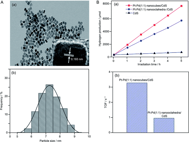 | ||
Fig. 23 (A) (a) TEM and high-resolution TEM images and (b) particle size distribution of Pt–Pd (1![[thin space (1/6-em)]](https://www.rsc.org/images/entities/char_2009.gif) : :![[thin space (1/6-em)]](https://www.rsc.org/images/entities/char_2009.gif) 1) alloy nanocubes (Pt–Pd (1 1) alloy nanocubes (Pt–Pd (1![[thin space (1/6-em)]](https://www.rsc.org/images/entities/char_2009.gif) : :![[thin space (1/6-em)]](https://www.rsc.org/images/entities/char_2009.gif) 1) nanocubes). (B) (a) Irradiation time course for H2 evolution over Pt–Pd (1 1) nanocubes). (B) (a) Irradiation time course for H2 evolution over Pt–Pd (1![[thin space (1/6-em)]](https://www.rsc.org/images/entities/char_2009.gif) : :![[thin space (1/6-em)]](https://www.rsc.org/images/entities/char_2009.gif) 1) nanocubes/CdS, Pt–Pd (1 1) nanocubes/CdS, Pt–Pd (1![[thin space (1/6-em)]](https://www.rsc.org/images/entities/char_2009.gif) : :![[thin space (1/6-em)]](https://www.rsc.org/images/entities/char_2009.gif) 1) nano-octahedra/CdS, and bare CdS photocatalysts. (b) Photocatalytic turnover frequencies (TOF) of Pt–Pd nanocubes/CdS and Pt–Pd nano-octahedra/CdS photocatalysts. Reproduced with permission from ref. 218. Copyright 2016 American Chemical Society. 1) nano-octahedra/CdS, and bare CdS photocatalysts. (b) Photocatalytic turnover frequencies (TOF) of Pt–Pd nanocubes/CdS and Pt–Pd nano-octahedra/CdS photocatalysts. Reproduced with permission from ref. 218. Copyright 2016 American Chemical Society. | ||
The shape and crystal plane of the photocatalyst also affect HER activity. In 2011, Sun et al.219 reported that the HER activity of TiO2 was improved when its morphology was modified to form cylindrical TiO2 nanotubes (TNT) (Fig. 24A(a)). In this study, CuO NPs were used as an HER cocatalyst. CuO NPs were loaded on TiO2 and TNT by adsorption and calcination (denoted as A–C; this is the same as liquid-phase adsorption) using Cu(NO3)2 as a precursor to form CuO NPs(A–C)/TiO2 and CuO NPs(A–C)/TNT, respectively (Fig. 24A(b)). For comparison, CuO NPs were also loaded on TiO2 and TNT by wet impregnation (WI) to give CuO NPs(WI)/TiO2 and CuO NPs(WI)/TNT, respectively (Fig. 24A(c)). The HER activity of this series of photocatalysts was measured in an aqueous solution containing methanol as a sacrificial agent. The results revealed that the HER activity of the photocatalysts increased in the following order: CuO NPs(A–C)/TNT > CuO NPs(WI)/TNT > CuO NPs(A–C)/TiO2 > CuO NPs(WI)/TiO2 (Fig. 24B). CuO NPs(A–C)/TNT showed the highest activity, which was higher than that of the corresponding photocatalyst using noble metal Pt/Ni NPs as a cocatalyst. Because TNTs are cylindrical, they have a high specific surface area (Fig. 24C). In addition, adsorption and calcination loaded cocatalyst NPs with higher dispersibility than that in the case of wet impregnation, and NP aggregation was less likely to occur in the former samples than in the latter. The high HER activity of CuO NPs(A–C)/TNT was ascribed to these factors.
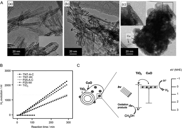 | ||
| Fig. 24 (A) High-resolution TEM images of (a) TNT, (b) TNT-A–C, and (c) TNT-WI photocatalysts. (B) Time courses of H2 evolution over the photocatalysts in (A) under irradiation. Inset: average H2 evolution rates over 5 h of reaction. (C) Schematic diagram of charge transfer in the CuO NPs/TNT photocatalyst under irradiation. Reproduced with permission from ref. 219. Copyright 2011 Elsevier Ltd. | ||
![[0 with combining macron]](https://www.rsc.org/images/entities/char_0030_0304.gif) 10) plane, they investigated the interface structure and electronic interaction between the Pt NC and CdS in this composite system by a DFT calculation (Fig. 25C). The results revealed that the electronic structure and local surface potential changed on both the Pt NC and CdS surfaces because of the strong geometrical and electronic interactions between them. They stated that understanding the structural and electronic interactions between the NCs and photocatalyst is important for elucidating the reaction mechanism to optimize hydrogen production.
10) plane, they investigated the interface structure and electronic interaction between the Pt NC and CdS in this composite system by a DFT calculation (Fig. 25C). The results revealed that the electronic structure and local surface potential changed on both the Pt NC and CdS surfaces because of the strong geometrical and electronic interactions between them. They stated that understanding the structural and electronic interactions between the NCs and photocatalyst is important for elucidating the reaction mechanism to optimize hydrogen production.
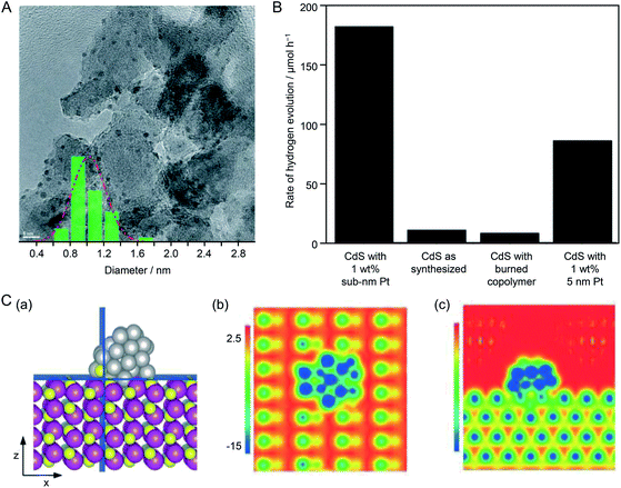 | ||
Fig. 25 (A) TEM image of 5 wt% Pt NCs loaded on Al2O3. The inset is the particle size distribution determined from the TEM image, showing an average Pt NC diameter of 0.9 ± 0.1 nm. (B) Rate of H2 evolution of CdS under different conditions. (C) Contours of electrostatic surface potential of Pt38 NC/CdS on cutting planes that are normal to the (b) z-axis and (c) x-axis, as highlighted in blue in the structural model in (a). z- and x-axes are along the [1![[0 with combining macron]](https://www.rsc.org/images/entities/char_0030_0304.gif) 10] and [0001] directions, respectively. Potential energies are in eV. Reproduced with permission from ref. 220. Copyright 2015 The Royal Society of Chemistry. 10] and [0001] directions, respectively. Potential energies are in eV. Reproduced with permission from ref. 220. Copyright 2015 The Royal Society of Chemistry. | ||
In the above study, although the cocatalyst (∼0.9 nm) was in the size range of NCs, it is not clear whether the number of constituent atoms was controlled with atomic precision. In recent years, there have been several studies using NCs with atomic precision as cocatalyst precursors. In 2017, Yang et al.221 studied the HER activity of photocatalyst systems using [Ag25(SPhMe2)18](PPh4) (SPhMe2 = 2,4-dimethylbenzenethiolate; PPh4 = tetraphenylphosphine) and [PtAg24(SPhMe2)18](PPh4)2 as cocatalyst precursors. [Ag25(SPhMe2)18](PPh4) and [PtAg24(SPhMe2)18](PPh4)2 were synthesized by the methods reported by Bakr et al.222 and Zhu et al.,223 respectively. Each type of NC was adsorbed on g-C3N4 by stirring for 12 h in a toluene/dichloromethane mixture with g-C3N4. The samples were calcined at 150 °C under flowing Ar for 2 h to yield Ag25 NC/g-C3N4 and PtAg24 NC/g-C3N4. Both types of NCs had a particle size of about 1 nm. The removal of the ligands was confirmed by photoelectron spectroscopy. X-ray photoelectron spectroscopy and X-ray absorption fine structure analyses confirmed that Pt and Ag were in a zero-valent oxidation state in the NCs loaded on the photocatalyst. The photocatalysts were dispersed in an aqueous solution containing TEOA as a sacrificial agent and irradiated with visible light (>420 nm) to induce the HER. It was found that PtAg24 NCs/g-C3N4 generated four times as much hydrogen as Ag25/g-C3N4. The HER activity of PtAg24 NC/g-C3N4 was 330 times higher than that of g-C3N4 without a cocatalyst (Fig. 26A and B). Open-circuit voltage decay (OCVD) measurements revealed that PtAg24 NC/g-C3N4 had a longer carrier lifetime than that of Ag25 NC/g-C3N4 (Fig. 26C). The high HER activity of PtAg24 NC/g-C3N4 was ascribed to effective trapping of the photoexcited electrons by Pt, which suppressed the recombination of electrons and holes (Fig. 26D). Thus, electron transfer was promoted by substituting one Ag atom of Ag25 with Pt, thereby improving the HER activity of the resulting NC-loaded photocatalyst.
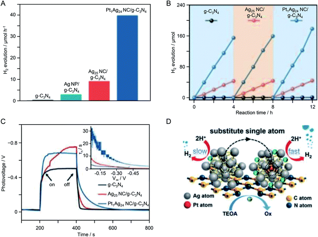 | ||
| Fig. 26 Photocatalytic H2 evolution performance. (A) Comparison of the photocatalytic H2 evolution activities of g-C3N4, Ag NPs/g-C3N4, Ag25 NC/g-C3N4, and PtAg24 NC/g-C3N4. (B) Cycling runs of photocatalytic H2 evolution over g-C3N4, Ag25 NC/g-C3N4, and PtAg24 NC/g-C3N4. (C) Transient OCVD measurements. The inset shows the average lifetimes of the photogenerated carriers (τn) obtained from the OCVD measurements. (D) Proposed photocatalytic H2 evolution mechanism. Reproduced with permission from ref. 221. Copyright 2017 The Royal Society of Chemistry. | ||
In 2018, Fang et al.224 also succeeded in improving the HER activity of g-C3N4 using precisely controlled metal NCs as a cocatalyst. They used Au25(Cys)18 with L-cysteine (Cys) as a ligand as a cocatalyst. First, Au25(Cys)18 (0.18, 0.49, or 0.96 wt%) and g-C3N4 were stirred in ethanol for 1 h to adsorb Au25(Cys)18 on g-C3N4. The obtained series of photocatalysts was dispersed in aqueous solutions containing TEOA as a sacrificial agent and then the HER was induced by irradiating the aqueous solution with visible light (>420 nm). The photocatalyst with 0.96 wt% Au25(Cys)18 exhibited the highest HER activity of the samples (Fig. 27A and B). Photoelectrochemical and photoluminescence measurements showed that the photocatalyst loaded with 0.96 wt% Au25(Cys)18 promoted charge separation to the greatest extent of the catalyst series. Based on these results, they concluded that the adsorption of Au25(Cys)18 not only provided HER active sites, but also induced effective interfacial charge transfer between the cocatalyst and g-C3N4 (Fig. 27C and D).
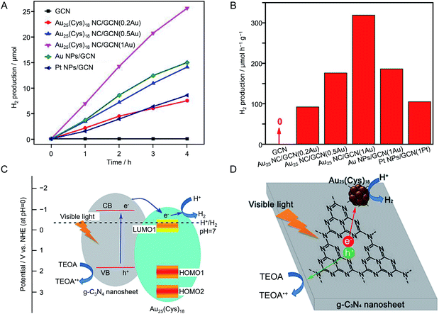 | ||
| Fig. 27 (A) Plots of photocatalytic H2 production under visible-light irradiation by g-C3N4 (GCN), Au25(Cys)18 NCs/GCN, Au NPs/GCN, and Pt NPs/GCN photocatalysts. (B) Rate of H2 evolution by various Au25(Cys)18 NCs/GCN photocatalysts under visible light. (C) Energy diagram and (D) schematic diagram of photocatalytic H2 evolution by Au25(Cys)18 NCs/GCN photocatalysts. Reproduced with permission from ref. 224. Copyright 2018 American Chemical Society. | ||
Thus, the precisely controlled NCs function as an effective HER cocatalysts. In addition, as described in Section 4.2, when precisely controlled NCs are used as a HER cocatalyst, it is easy to analyze the structure of the cocatalyst and clarify the origin of the improved activity. To utilize the advantages of such precise NCs, it is necessary to suppress aggregation of the cocatalyst on the photocatalyst surface. Section 4.2 revealed that the formation of a Cr2O3 shell suppressed both cocatalyst aggregation and the reverse reaction of water splitting. In 2019, Shi et al.225 revealed that encapsulating precisely controlled NCs with metal–organic frameworks (MOFs) can also suppress the aggregation of NCs. In this study, Au25 was used as a precisely controlled NC and ZIF-8 was used as the MOF. First, Au25(SG)18 (∼1.2 nm) was encapsulated into ZIF-8 by a coordination-assisted self-assembly strategy. Next, TiO2 crystals were grown on the ZIF-8 surface by a hydrothermal method. Finally, a rhenium (Re) complex was adsorbed on the surface of the TiO2 crystals to form ZIF-8/Au25(SG)18 NC/TiO2-ReP with an Au content of 0.5 wt% (Fig. 28A). In this photocatalyst, Au25(SG)18 was used as an HER cocatalyst and the Re complex was used as a cocatalyst for the CO2 reduction reaction. TEM measurements confirmed that during the preparation of ZIF-8/Au25(SG)18 NC/TiO2-ReP, the aggregation of Au25(SG)18 NC hardly occurred. The obtained photocatalyst was dispersed in an aqueous solution containing TEOA as a sacrificial agent and irradiated with visible light (>420 nm) to induce the HER and CO2 reduction reaction. The HER activity of ZIF-8/Au25(SG)18 NC/TiO2-ReP was about twice that of the case using Au NPs (∼10 nm) as the HER cocatalyst. The turnover frequency of ZIF-8/Au25(SG)18 NC/TiO2-ReP was 87 h−1 (based on an Au content of 0.5 wt%) and its apparent quantum yield at 500 nm was 2.06%. No decrease in activity was observed even when the light irradiation was continued for 7.5 h. In addition, high-angle annular dark field-STEM-energy-dispersive X-ray spectroscopy measurements indicated that the monodispersity of the Au25(SG)18 NC in ZIF-8/Au25(SG)18 NC/TiO2-ReP was maintained after the photocatalytic reaction (Fig. 28B). These results demonstrated that encapsulating the cocatalyst with an MOF is also an effective way to produce stable and highly active photocatalysts.
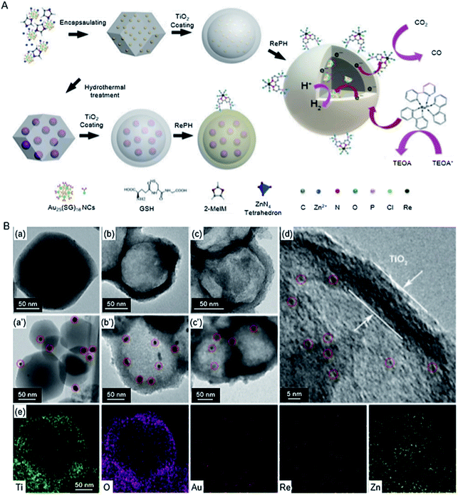 | ||
| Fig. 28 (A) Fabrication of ZIF-8/Au25(SG)18 NC/TiO2-ReP and ZIF-8/Au NPs/TiO2-ReP composite photocatalysts by hydrothermal growth of a TiO2 shell followed by grafting of RePH molecules, and the photocatalytic processes of CO2 reduction and H2 generation over ZIF-8/Au25(SG)18 NC/TiO2-ReP under visible-light irradiation. (B) TEM images of (a) ZIF-8/Au25(SG)18 NC, (b) ZIF-8/Au25(SG)18 NC/TiO2, (c) ZIF-8/Au25(SG)18 NC/TiO2-ReP, (a′) ZIF-8/Au NPs, (b′) ZIF-8/Au NPs/TiO2, and (c′) ZIF-8/Au NPs/TiO2-ReP, and (d) high-resolution TEM image and (e) elemental maps of ZIF-8/Au25(SG)18 NC/TiO2-ReP. Green: Ti, purple: O, red: Au, pink: Re, yellow: Zn. Reproduced with permission from ref. 225. Copyright 2019 Royal Society of Chemistry. | ||
4.3. Application in O2 evolution
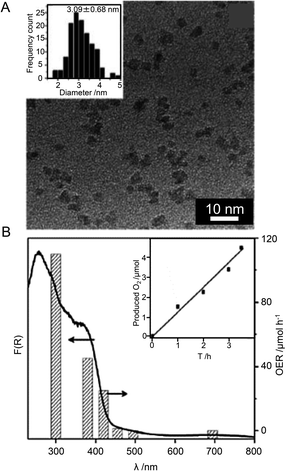 | ||
| Fig. 29 (A) TEM image of as-prepared Co3O4 NPs. (B) Wavelength dependence O2 evolution rate over 3 wt% Co3O4 NPs/g-C3N4. The inset is the O2 evolution curves under visible light (λ > 455 nm). Reproduced with permission from ref. 227. Copyright 2017 Royal Society of Chemistry. | ||
| Semiconductor | Cocatalyst | Light source | Reactant solution | Ref. | ||
|---|---|---|---|---|---|---|
| Kinds | Loading amount | Size | ||||
| g-C3N4 | Co3O4 NPs | 3 wt% | ∼3 nm | 300 W Xe lamp (λ > 455 nm) | 0.01 M AgNO3 aq. | 227 |
5. Information on interface between NPs/NCs and photocatalysts
In order to improve the functionality of water-splitting photocatalysts on the basis of the design guidelines, it is essential to elucidate the charge transfer rate, geometric and electronic structures, and interactions at the interface of NPs/NCs-photocatalysts. The measurements of the transient absorption and fluorescence decay are effective ways to determine the charge transfer rate.230–235 For example, Lee et al. measured fluorescence decay of Aun(SG)m NPs/ZnO and thereby elucidated that the rate of the charge transfer at the interface is enhanced as the size of the Aun(SG)m increases.235 For the elucidation of the geometrical/electronic structure of the loaded NPs/NCS and the surface of the substrate, scanning probing microscope (SPM) is a powerful tool.236–238 For example, Diebold et al. successfully elucidated the growth pattern of Au NPs and Pt NCs on the surface (101) of anatase-type TiO2 using the scanning tunneling microscope.236 DFT calculations are promising for understanding the geometrical and electronic interaction at the interface.239–243 For example, Libuda et al. performed DFT calculations on the model of Pt NPs/CeO2 catalyst and found that there are two kinds of the strong interactions between Pt NPs and CeO2, the electron transfer from Pt NPs to CeO2 and the oxygen transfer from CeO2 to Pt NPs. The latter effect was found to be unique to nanoscale CeO2.239Thus, spectroscopy, SPM, and DFT calculations are powerful tools for elucidating the phenomenon occurred at the interface of NPs/NCs-photocatalysis. In addition to these methods, electrochemical measurements are also useful for predicting the appropriate cocatalysts121,122,244 because the overpotential obtained by electrochemical measurements are strongly related to the activation energy of each reaction. At present, these measurements and analyses have not been necessarily conducted for the photocatalysts described in Section 4. However, these measurements and analyses should be conducted also for the studies using the advanced water-splitting photocatalysts (Section 4). The results would provide a deeper understanding of their interfaces and enable us to predict the appropriate elements, size, and geometric structure of the cocatalysts suitable for obtaining highly active photocatalysts.
6. Summary
This review summarized recent studies on the application of metal NPs/NCs in water-splitting photocatalysis. Through this summary, the followings points regarding cocatalyst control were clarified.(i) The use of precise synthesis and structure control techniques (nanotechnology) established in the fields of colloid, NP, and NC chemistry are effective for controlling the cocatalysts of water-splitting photocatalysts to obtain highly active water-splitting photocatalysts. At present, the kinds of ligands of the NPs/NCs and the photocatalysts used for liquid-phase adsorption method are limited to several species because this type of study just started in recent years. However, considering the mechanism (Section 3.2), other ligand-protected metal NPs/NCs245 and photocatalysts131 seem to be also applicable to the liquid-phase adsorption method.
(ii) To control a cocatalyst, it is very important to select appropriate elements, refine the particle size, improve dispersibility, form an alloy, form a shell with controlled thickness that suppresses the reverse reaction, expose a suitable crystal face, and control the charge state.
(iii) The formation of a shell that suppresses the reverse reaction is effective to enhance both the activity and stability of the cocatalyst.
(iv) Although the above-mentioned approaches provide an overall guidance to enhance cocatalyst activity, the most effective means to achieve high activation differs slightly depending on the combination of photocatalyst and cocatalyst.
(v) In one-step photoexcitation systems for overall water splitting, control of both HER and OER cocatalysts is effective for enhancing the overall activity of water-splitting photocatalysts.
(vi) For Z-scheme catalysts, reduction of the mediator may be rate-determining. Thus, control of the cocatalyst that promotes mediator reduction is an effective approach to increase the rate of this reaction.
(vii) Using precisely controlled NC cocatalysts provides a deeper understanding of geometrical structure and electronic state of the cocatalyst, and thereby greater knowledge of the main factors influencing photocatalyst activation.
These findings are expected to be useful for researchers in the field of water-splitting photocatalysis, as well as those interesting in the applications of controlled NPs/NCs.
7. Outlook
As mentioned above, it is necessary to improve the STH of a water-splitting photocatalyst to 10% or more to enable its practical use. Thus, the following studies are considered important in the future.(i) Close collaboration between photocatalyst chemists and NP/NC chemists. To enhance the activity of water-splitting photocatalysts, it is necessary to improve both the semiconductor photocatalyst and cocatalyst. Regarding semiconductor photocatalysts, photocatalysis researchers would continue to make substantial improvements. On the other hand, the recent studies revealed that the use of precise synthesis and structure control techniques established in the fields of colloid, NP, and NC chemistry is very effective at raising cocatalyst activity. Therefore, researchers in the field of NPs/NCs should also conduct thorough research on enhancing the activity of cocatalysts. Effective approaches to maximize activation depend on the specific combination of photocatalyst and cocatalyst. If NCs/NPs researchers continue to conduct cocatalyst research using commercial photocatalysts, the results would not lead to the high activation of the most advanced photocatalysts. To develop highly active water-splitting photocatalysts for practical use, researchers in both fields need to collaborate more closely in future research.
(ii) Selective loading of cocatalysts on the optimal crystal plane. The crystal planes of semiconductor photocatalysts show different transport rates of photogenerated electrons and holes. If HER and OER cocatalysts could be selectively loaded on crystal planes with rapid electron and hole transport, electrons and holes could be efficiently used in the relevant reactions. In fact, research on photocatalysts in which a cocatalyst was loaded by photodeposition demonstrated that such selective cocatalyst deposition is an effective approach to increase activation.246 In the case of photodeposition, the HER cocatalyst is formed by reduction of metal ions and the OER cocatalyst is formed by oxidation of metal ions. Therefore, each cocatalyst is inevitably loaded on a crystal plane where electrons and holes can easily reach the active sites. Even for colloidal NPs/NCs, if such crystal plane-selective loading can be achieved, higher activity should be obtained compared with that provided by the present method. One of the methods seems to adsorb the colloidal metal NPs/NCs on the photocatalyst after a particular crystal-plane which is undesired site are selectively covered with a surfactant.
(iii) Control of the geometrical structure of loaded NPs/NCs. The geometrical structure of loaded NPs/NCs appears to show some variation. In the case of NPs, the size distribution occurs at the synthesis stage. In the case of NCs, there is no variation in size (chemical composition) and geometrical structure at the synthesis stage, but the NCs after loading sometimes seem to have varied geometrical structure. To identify the geometrical structures of NPs/NCs that lead to high activity and selectively load NPs/NCs with such geometrical structures as cocatalysts, it is necessary to establish a new method for controlling the geometrical structure of the loaded NPs/NCs. For NPs/NCs dispersed in solution, post-treatment methods for size247 and structure convergence55 have been reported. In the future, it is expected that post-treatment to achieve size and structure convergence will also be established for loaded NPs/NCs, which would realize the loading of NPs/NCs with controlled geometrical structure.
(iv) Elucidation of the calcination process. Protective organic molecules on colloidal metal NPs/NCs are often removed by calcination. However, the presence or absence of protective organic molecules is generally determined only by X-ray photoelectron spectroscopy and/or X-ray absorption fine structure measurements. In the case of NCs, although NCs are synthesized while controlling the chemical composition at the atomic/molecular level, ambiguity remains about the elimination of the protective ligands. For ultrafine NCs, the remaining protective ligands should strongly affect the electronic/geometrical structure of the NCs. To obtain reliable design guidelines for improving the activity of cocatalysts, it is necessary to determine whether or not the protective ligands remain on the NCs at the atomic/molecular level. Thus, it is necessary to gain a deep understanding of the calcination mechanism and to further improve the structural analysis techniques for loaded NCs. If the calcination mechanism can be clarified at the molecular level, it will not be necessary to consider the protective ligands remaining after calcination and will also be possible to conduct calcination at an appropriate temperature to suppress cocatalyst aggregation on the photocatalyst. This understanding is also necessary for better control of the geometrical structure of loaded NCs.
(v) Utilization of various metal NPs/NCs. In recent years, it has become possible to synthesize various monodisperse NPs/NCs with controlled size and structure. Inorganic chemists can now synthesize metal NCs as precisely as organic chemists synthesize organic molecules, and the types of synthesized NCs are steadily increasing. However, the types of NPs/NCs used in the study of water-splitting photocatalysts are limited. In the future, more of the existing NPs/NCs should be used in water-splitting photocatalysis research. This would expand knowledge of the major factors affecting cocatalyst activity and increase the possibility of producing photocatalysts with high water-splitting activity.
(vi) Theoretical calculations of real systems. For understanding the main factors influencing the activity, theoretical research using the actual geometrical structures is required. At present, deep understanding of the chemical composition and geometrical structure of loaded NPs/NCs and their loading sites on photocatalysts have not been obtained experimentally. In the future, it is expected that the structural analysis techniques for loaded NCs will be improved and thereby enable theoretical calculations to be carried out using actual geometrical structures obtained by such experiments. If such a progress would be achieved, it became possible to predict appropriate photocatalyst systems by DFT calculations.
We hope that by overcoming these current limitations of water-splitting photocatalysts, a society able to solve energy and environmental problems will emerge as soon as possible.
Authors contributions
Y. Negishi constructed the structure of this review. T. Kawawaki, Y. Mori, K. Wakamatsu, S. Ozaki, and M. Kawachi surveyed the literature, compiled figures and tables, and wrote the manuscript. Y. Negishi and S. Hossain revised the entire draft before submission. All authors have approved the final version of the manuscript.Conflicts of interest
There are no conflicts to declare.Acknowledgements
This work was supported by the Japan Society for the Promotion of Science (JSPS) KAKENHI (grant number JP16H04099, 16K21402, 20H02698, 20H02552), Scientific Research on Innovative Areas “Coordination Asymmetry” (grant number 17H05385 and 19H04595), and Scientific Research on Innovative Areas “Innovations for Light-Energy Conversion” (grant number 18H05178 and 20H05115). Funding from Asahi Glass Foundation, TEPCO Memorial Foundation Research Grant (Basic Research), and Kato Foundation for Promotion of Science (grant number KJ-2904) are also gratefully acknowledged.References
- C. N. R. Rao, P. J. Thomas and G. U. Kulkarni, Nanocrystals: Synthesis, Properties and Applications, Springer, Berlin Heidelberg, Germany, 2007 Search PubMed.
- B. Corain, G. Schmid and N. Toshima, Metal Nanoclusters in Catalysis and Materials Science: The Issue of Size Control, Elsevier B.V., Amsterdam, The Netherlands, 2008 Search PubMed.
- M. Faraday, Philos. Trans. R. Soc. London, 1857, 147, 145–181 CrossRef.
- C. M. Cobley, J. Chen, E. C. Cho, L. V. Wang and Y. Xia, Chem. Soc. Rev., 2011, 40, 44–56 RSC.
- H.-L. Wu, R. Sato, A. Yamaguchi, M. Kimura, M. Haruta, H. Kurata and T. Teranishi, Science, 2016, 351, 1306–1310 CrossRef CAS PubMed.
- T. Kawawaki, T. Nakagawa, M. Sakamoto and T. Teranishi, J. Am. Chem. Soc., 2019, 141, 8402–8406 CrossRef CAS PubMed.
- N. L. Rosi, D. A. Giljohann, C. S. Thaxton, A. K. R. Lytton-Jean, M. S. Han and C. A. Mirkin, Science, 2006, 312, 1027–1030 CrossRef CAS PubMed.
- H. Zhang, T. Watanabe, M. Okumura, M. Haruta and N. Toshima, Nat. Mater., 2012, 11, 49–52 CrossRef PubMed.
- B. Huang, H. Kobayashi, T. Yamamoto, S. Matsumura, Y. Nishida, K. Sato, K. Nagaoka, S. Kawaguchi, Y. Kubota and H. Kitagawa, J. Am. Chem. Soc., 2017, 139, 4643–4646 CrossRef CAS PubMed.
- T. Kawawaki, H. Wang, T. Kubo, K. Saito, J. Nakazaki, H. Segawa and T. Tatsuma, ACS Nano, 2015, 9, 4165–4172 CrossRef CAS PubMed.
- T. Matsuura, K. Imaeda, S. Hasegawa, H. Suzuki and K. Imura, J. Phys. Chem. Lett., 2019, 10, 819–824 CrossRef CAS PubMed.
- N. J. Halas, S. Lal, W.-S. Chang, S. Link and P. Nordlander, Chem. Rev., 2011, 111, 3913–3961 CrossRef CAS PubMed.
- M. Sadakiyo, M. Kon-no, K. Sato, K. Nagaoka, H. Kasai, K. Kato and M. Yamauchi, Dalton Trans., 2014, 43, 11295–11298 RSC.
- R. Takahata and T. Tsukuda, Chem. Lett., 2019, 48, 906–915 CrossRef CAS.
- T. Yonezawa, S. Onoue and N. Kimizuka, Adv. Mater., 2001, 13, 140–142 CrossRef CAS.
- M. Basu, A. K. Sinha, M. Pradhan, S. Sarkar, Y. Negishi, Govind and T. Pal, Environ. Sci. Technol., 2010, 44, 6313–6318 CrossRef CAS PubMed.
- F. Mafuné, J.-y. Kohno, Y. Takeda, T. Kondow and H. Sawabe, J. Phys. Chem. B, 2000, 104, 9111–9117 CrossRef.
- H. Kawasaki, Nanotechnol. Rev., 2013, 2, 5–25 CAS.
- Y.-w. Jun, J.-H. Lee and J. Cheon, Angew. Chem., Int. Ed., 2008, 47, 5122–5135 CrossRef CAS PubMed.
- K. G. Thomas and P. V. Kamat, J. Am. Chem. Soc., 2000, 122, 2655–2656 CrossRef CAS.
- T. Suzuki, K.-i. Okazaki, S. Suzuki, T. Shibayama, S. Kuwabata and T. Torimoto, Chem. Mater., 2010, 22, 5209–5215 CrossRef CAS.
- M. Miyachi, Y. Yamanoi, Y. Shibata, H. Matsumoto, K. Nakazato, M. Konno, K. Ito, Y. Inoue and H. Nishihara, Chem. Commun., 2010, 46, 2557–2559 RSC.
- T. Oshikiri, K. Ueno and H. Misawa, Angew. Chem., Int. Ed., 2016, 55, 3942–3946 CrossRef CAS PubMed.
- K. L. Kelly, E. Coronado, L. L. Zhao and G. C. Schatz, J. Phys. Chem. B, 2003, 107, 668–677 CrossRef CAS.
- Y. Tian and T. Tatsuma, J. Am. Chem. Soc., 2005, 127, 7632–7637 CrossRef CAS PubMed.
- Y. Takahashi, Y. Sota, T. Ishida, Y. Furukawa and S. Yamada, J. Phys. Chem. C, 2020, 124, 4202–4205 CrossRef CAS.
- R. B. M. Schasfoort, Handbook of Surface Plasmon Resonance, Royal Society of Chemistry, Cambridge, 2017 Search PubMed.
- S.-Y. Ding, J. Yi, J.-F. Li, B. Ren, D.-Y. Wu, R. Panneerselvam and Z.-Q. Tian, Nat. Rev. Mater., 2016, 1, 16021 CrossRef CAS.
- F. Toderas, M. Baia, L. Baia and S. Astilean, Nanotechnology, 2007, 18, 255702 CrossRef.
- B.-H. Sohn, J.-M. Choi, S. I. Yoo, S.-H. Yun, W.-C. Zin, J. C. Jung, M. Kanehara, T. Hirata and T. Teranishi, J. Am. Chem. Soc., 2003, 125, 6368–6369 CrossRef CAS PubMed.
- R. Singh and J. W. Lillard, Exp. Mol. Pathol., 2009, 86, 215–223 CrossRef CAS PubMed.
- S. M. Lang and T. M. Bernhardt, Phys. Chem. Chem. Phys., 2012, 14, 9255–9269 RSC.
- T. Tsukuda and H. Häkkinen, Protected Metal Clusters: From Fundamentals to Applications, Elsevier B.V., Amsterdam, The Netherlands, 2015 Search PubMed.
- R. Jin, C. Zeng, M. Zhou and Y. Chen, Chem. Rev., 2016, 116, 10346–10413 CrossRef CAS PubMed.
- R. Jin, Nanoscale, 2010, 2, 343–362 RSC.
- R. R. Nasaruddin, T. Chen, N. Yan and J. Xie, Coord. Chem. Rev., 2018, 368, 60–79 CrossRef CAS.
- Y. Du, H. Sheng, D. Astruc and M. Zhu, Chem. Rev., 2020, 120, 526–622 CrossRef CAS PubMed.
- N. A. Sakthivel and A. Dass, Acc. Chem. Res., 2018, 51, 1774–1783 CrossRef CAS PubMed.
- H. Kawasaki, S. Kumar, G. Li, C. Zeng, D. R. Kauffman, J. Yoshimoto, Y. Iwasaki and R. Jin, Chem. Mater., 2014, 26, 2777–2788 CrossRef CAS.
- K. Yamamoto, T. Imaoka, M. Tanabe and T. Kambe, Chem. Rev., 2020, 120, 1397–1437 CrossRef PubMed.
- R. L. Whetten, H.-C. Weissker, J. J. Pelayo, S. M. Mullins, X. López-Lozano and I. L. Garzón, Acc. Chem. Res., 2019, 52, 34–43 CrossRef CAS PubMed.
- S. Sharma, K. K. Chakrahari, J.-Y. Saillard and C. W. Liu, Acc. Chem. Res., 2018, 51, 2475–2483 CrossRef CAS PubMed.
- M.-L. Cui, Y.-S. Chen, Q.-F. Xie, D.-P. Yang and M.-Y. Han, Coord. Chem. Rev., 2019, 387, 450–462 CrossRef CAS.
- J. Fang, B. Zhang, Q. Yao, Y. Yang, J. Xie and N. Yan, Coord. Chem. Rev., 2016, 322, 1–29 CrossRef CAS.
- T.-Q. Yang, B. Peng, B.-Q. Shan, Y.-X. Zong, J.-G. Jiang, P. Wu and K. Zhang, Nanomaterials, 2020, 10, 261 CrossRef CAS PubMed.
- Y. Negishi, W. Kurashige, Y. Niihori, T. Iwasa and K. Nobusada, Phys. Chem. Chem. Phys., 2010, 12, 6219–6225 RSC.
- Y. Negishi, T. Iwai and M. Ide, Chem. Commun., 2010, 46, 4713–4715 RSC.
- Y. Negishi, W. Kurashige, Y. Kobayashi, S. Yamazoe, N. Kojima, M. Seto and T. Tsukuda, J. Phys. Chem. Lett., 2013, 4, 3579–3583 CrossRef CAS.
- Y. Negishi, K. Munakata, W. Ohgake and K. Nobusada, J. Phys. Chem. Lett., 2012, 3, 2209–2214 CrossRef CAS PubMed.
- Y. Niihori, M. Matsuzaki, T. Pradeep and Y. Negishi, J. Am. Chem. Soc., 2013, 135, 4946–4949 CrossRef CAS PubMed.
- Y. Niihori, M. Matsuzaki, C. Uchida and Y. Negishi, Nanoscale, 2014, 6, 7889–7896 RSC.
- Y. Niihori, Y. Kikuchi, A. Kato, M. Matsuzaki and Y. Negishi, ACS Nano, 2015, 9, 9347–9356 CrossRef CAS PubMed.
- Y. Niihori, M. Eguro, A. Kato, S. Sharma, B. Kumar, W. Kurashige, K. Nobusada and Y. Negishi, J. Phys. Chem. C, 2016, 120, 14301–14309 CrossRef CAS.
- Y. Niihori, Y. Koyama, S. Watanabe, S. Hashimoto, S. Hossain, L. V. Nair, B. Kumar, W. Kurashige and Y. Negishi, J. Phys. Chem. Lett., 2018, 9, 4930–4934 CrossRef CAS PubMed.
- Y. Niihori, S. Hashimoto, Y. Koyama, S. Hossain, W. Kurashige and Y. Negishi, J. Phys. Chem. C, 2019, 123, 13324–13329 CrossRef CAS.
- Y. Niihori, D. Shima, K. Yoshida, K. Hamada, L. V. Nair, S. Hossain, W. Kurashige and Y. Negishi, Nanoscale, 2018, 10, 1641–1649 RSC.
- T. G. Dietz, M. A. Duncan, D. E. Powers and R. E. Smalley, J. Chem. Phys., 1981, 74, 6511–6512 CrossRef CAS.
- R. E. Leuchtner, A. C. Harms and A. W. Castleman Jr, J. Chem. Phys., 1989, 91, 2753–2754 CrossRef CAS.
- G. Ganteför, K. H. Meiwes-Broer and H. O. Lutz, Phys. Rev. A: At., Mol., Opt. Phys., 1988, 37, 2716–2718 CrossRef PubMed.
- J. R. R. Verlet, A. E. Bragg, A. Kammrath, O. Cheshnovsky and D. M. Neumark, J. Chem. Phys., 2004, 121, 10015–10025 CrossRef CAS PubMed.
- K. Miyajima, N. Fukushima, H. Himeno, A. Yamada and F. Mafuné, J. Phys. Chem. A, 2009, 113, 13448–13450 CrossRef CAS PubMed.
- A. Nakajima, K. Hoshino, K. Watanabe, Y. Konishi, T. Kurikawa, S. Iwata and K. Kaya, Chem. Phys. Lett., 1994, 222, 353–357 CrossRef CAS.
- Y. Negishi, Y. Nakamura, A. Nakajima and K. Kaya, J. Chem. Phys., 2001, 115, 3657–3663 CrossRef CAS.
- K. Tono, A. Terasaki, T. Ohta and T. Kondow, Chem. Phys. Lett., 2007, 449, 276–281 CrossRef CAS.
- T. Watanabe and T. Tsukuda, J. Phys. Chem. C, 2013, 117, 6664–6668 CrossRef CAS.
- A. von Weber and S. L. Anderson, Acc. Chem. Res., 2016, 49, 2632–2639 CrossRef CAS PubMed.
- Y. Negishi, H. Kawamata, A. Nakajima and K. Kaya, J. Electron Spectrosc. Relat. Phenom., 2000, 106, 117–125 CrossRef CAS.
- J. Li, X. Li, H.-J. Zhai and L.-S. Wang, Science, 2003, 299, 864–867 CrossRef CAS PubMed.
- K. Judai, S. Abbet, A. S. Wörz, U. Heiz and C. R. Henry, J. Am. Chem. Soc., 2004, 126, 2732–2737 CrossRef CAS PubMed.
- C. E. Briant, B. R. C. Theobald, J. W. White, L. K. Bell, D. M. P. Mingos and A. J. Welch, J. Chem. Soc., Chem. Commun., 1981, 201–202 RSC.
- G. Schmid, R. Pfeil, R. Boese, F. Bandermann, S. Meyer, G. H. M. Calis and J. W. A. van der Velden, Chem. Ber., 1981, 114, 3634–3642 CrossRef CAS.
- S. S. Kurasov, N. K. Eremenko, Y. L. Slovokhotov and Y. T. Struchkov, J. Organomet. Chem., 1989, 361, 405–408 CrossRef CAS.
- M. McPartlin, R. Mason and L. Malatesta, J. Chem. Soc. D, 1969, 334 RSC.
- E. G. Mednikov and L. F. Dahl, Philos. Trans. R. Soc., A, 2010, 368, 1301–1332 CrossRef CAS PubMed.
- G. Schmid, Chem. Rev., 1992, 92, 1709–1727 CrossRef CAS.
- M. Schulz-Dobrick and M. Jansen, Z. Anorg. Allg. Chem., 2007, 633, 2326–2331 CrossRef CAS.
- B. K. Teo, X. Shi and H. Zhang, J. Am. Chem. Soc., 1992, 114, 2743–2745 CrossRef CAS.
- F. A. Vollenbroek, J. J. Bour and J. W. A. van der Veden, Recl. Trav. Chim. Pays-Bas, 1980, 99, 137–141 CrossRef CAS.
- I. Chakraborty and T. Pradeep, Chem. Rev., 2017, 117, 8208–8271 CrossRef CAS PubMed.
- M. Brust, M. Walker, D. Bethell, D. J. Schiffrin and R. Whyman, J. Chem. Soc., Chem. Commun., 1994, 801–802 RSC.
- Y. Negishi, K. Nobusada and T. Tsukuda, J. Am. Chem. Soc., 2005, 127, 5261–5270 CrossRef CAS PubMed.
- M. Agrachev, M. Ruzzi, A. Venzo and F. Maran, Acc. Chem. Res., 2019, 52, 44–52 CrossRef CAS PubMed.
- B. Bhattarai, Y. Zaker, A. Atnagulov, B. Yoon, U. Landman and T. P. Bigioni, Acc. Chem. Res., 2018, 51, 3104–3113 CrossRef CAS PubMed.
- Z. Gan, N. Xia and Z. Wu, Acc. Chem. Res., 2018, 51, 2774–2783 CrossRef CAS PubMed.
- A. Ghosh, O. F. Mohammed and O. M. Bakr, Acc. Chem. Res., 2018, 51, 3094–3103 CrossRef CAS PubMed.
- S. Hossain, Y. Niihori, L. V. Nair, B. Kumar, W. Kurashige and Y. Negishi, Acc. Chem. Res., 2018, 51, 3114–3124 CrossRef CAS PubMed.
- K. Kwak and D. Lee, Acc. Chem. Res., 2019, 52, 12–22 CrossRef CAS PubMed.
- B. Nieto-Ortega and T. Bürgi, Acc. Chem. Res., 2018, 51, 2811–2819 CrossRef CAS PubMed.
- J. Yan, B. K. Teo and N. Zheng, Acc. Chem. Res., 2018, 51, 3084–3093 CrossRef CAS PubMed.
- Q. Yao, T. Chen, X. Yuan and J. Xie, Acc. Chem. Res., 2018, 51, 1338–1348 CrossRef CAS PubMed.
- M. A. Bakar, M. Sugiuchi, M. Iwasaki, Y. Shichibu and K. Konishi, Nat. Commun., 2017, 8, 576 CrossRef PubMed.
- Q.-F. Zhang, X. Chen and L.-S. Wang, Acc. Chem. Res., 2018, 51, 2159–2168 CrossRef CAS PubMed.
- Z. Lei, X.-K. Wan, S.-F. Yuan, Z.-J. Guan and Q.-M. Wang, Acc. Chem. Res., 2018, 51, 2465–2474 CrossRef CAS PubMed.
- S. Takano, S. Hasegawa, M. Suyama and T. Tsukuda, Acc. Chem. Res., 2018, 51, 3074–3083 CrossRef CAS PubMed.
- Y. Niihori, W. Kurashige, M. Matsuzaki and Y. Negishi, Nanoscale, 2013, 5, 508–512 RSC.
- S. Xie, H. Tsunoyama, W. Kurashige, Y. Negishi and T. Tsukuda, ACS Catal., 2012, 2, 1519–1523 CrossRef CAS.
- Y. Negishi, K. Igarashi, K. Munakata, W. Ohgake and K. Nobusada, Chem. Commun., 2012, 48, 660–662 RSC.
- S. Yamazoe, W. Kurashige, K. Nobusada, Y. Negishi and T. Tsukuda, J. Phys. Chem. C, 2014, 118, 25284–25290 CrossRef CAS.
- S. Hossain, T. Ono, M. Yoshioka, G. Hu, M. Hosoi, Z. Chen, L. V. Nair, Y. Niihori, W. Kurashige, D.-e. Jiang and Y. Negishi, J. Phys. Chem. Lett., 2018, 9, 2590–2594 CrossRef CAS PubMed.
- S. Sharma, W. Kurashige, K. Nobusada and Y. Negishi, Nanoscale, 2015, 7, 10606–10612 RSC.
- S. Sharma, S. Yamazoe, T. Ono, W. Kurashige, Y. Niihori, K. Nobusada, T. Tsukuda and Y. Negishi, Dalton Trans., 2016, 45, 18064–18068 RSC.
- L. V. Nair, S. Hossain, S. Takagi, Y. Imai, G. Hu, S. Wakayama, B. Kumar, W. Kurashige, D.-e. Jiang and Y. Negishi, Nanoscale, 2018, 10, 18969–18979 RSC.
- W. Kurashige, M. Yamaguchi, K. Nobusada and Y. Negishi, J. Phys. Chem. Lett., 2012, 3, 2649–2652 CrossRef CAS PubMed.
- W. Kurashige, K. Munakata, K. Nobusada and Y. Negishi, Chem. Commun., 2013, 49, 5447–5449 RSC.
- S. Hossain, Y. Imai and Y. Negishi, AIP Conf. Proc., 2019, 2186, 030018 CrossRef.
- S. Hossain, Y. Imai, Y. Motohashi, Z. Chen, D. Suzuki, T. Suzuki, Y. Kataoka, M. Hirata, T. Ono, W. Kurashige, T. Kawawaki, T. Yamamoto and Y. Negishi, Mater. Horiz., 2020, 7, 796–803 RSC.
- S. Hossain, Y. Imai, D. Suzuki, W. Choi, Z. Chen, T. Suzuki, M. Yoshioka, T. Kawawaki, D. Lee and Y. Negishi, Nanoscale, 2019, 11, 22089–22098 RSC.
- Y. Shichibu, Y. Negishi, T. Watanabe, N. K. Chaki, H. Kawaguchi and T. Tsukuda, J. Phys. Chem. C, 2007, 111, 7845–7847 CrossRef CAS.
- N. Barrabés, B. Zhang and T. Bürgi, J. Am. Chem. Soc., 2014, 136, 14361–14364 CrossRef PubMed.
- P. D. Jadzinsky, G. Calero, C. J. Ackerson, D. A. Bushnell and R. D. Kornberg, Science, 2007, 318, 430–433 CrossRef CAS PubMed.
- M. W. Heaven, A. Dass, P. S. White, K. M. Holt and R. W. Murray, J. Am. Chem. Soc., 2008, 130, 3754–3755 CrossRef CAS PubMed.
- M. Zhu, C. M. Aikens, F. J. Hollander, G. C. Schatz and R. Jin, J. Am. Chem. Soc., 2008, 130, 5883–5885 CrossRef CAS PubMed.
- H. Qian, W. T. Eckenhoff, Y. Zhu, T. Pintauer and R. Jin, J. Am. Chem. Soc., 2010, 132, 8280–8281 CrossRef CAS PubMed.
- Y. Chen, C. Zeng, C. Liu, K. Kirschbaum, C. Gayathri, R. R. Gil, N. L. Rosi and R. Jin, J. Am. Chem. Soc., 2015, 137, 10076–10079 CrossRef CAS PubMed.
- T. Kawawaki, Y. Negishi and H. Kawasaki, Nanoscale Adv., 2020, 2, 17–36 RSC.
- T. Kawawaki and Y. Negishi, Nanomaterials, 2020, 10, 238 CrossRef CAS PubMed.
- A. Munir, K. S. Joya, T. Ul haq, N.-U.-A. Babar, S. Z. Hussain, A. Qurashi, N. Ullah and I. Hussain, ChemSusChem, 2019, 12, 1517–1548 CrossRef CAS PubMed.
- R. Shi, Y. Cao, Y. Bao, Y. Zhao, G. I. N. Waterhouse, Z. Fang, L.-Z. Wu, C.-H. Tung, Y. Yin and T. Zhang, Adv. Mater., 2017, 29, 1700803 CrossRef PubMed.
- L. Shang, Y. Liang, M. Li, G. I. N. Waterhouse, P. Tang, D. Ma, L.-Z. Wu, C.-H. Tung and T. Zhang, Adv. Funct. Mater., 2017, 27, 1606215 CrossRef.
- Y. Cao, J. Guo, R. Shi, G. I. N. Waterhouse, J. Pan, Z. Du, Q. Yao, L.-Z. Wu, C.-H. Tung, J. Xie and T. Zhang, Nat. Commun., 2018, 9, 2379 CrossRef PubMed.
- J. Lu, Z. Tang, L. Luo, S. Yin, P. Kang Shen and P. Tsiakaras, Appl. Catal., B, 2019, 255, 117737 CrossRef CAS.
- L. Zhang, J. Lu, S. Yin, L. Luo, S. Jing, A. Brouzgou, J. Chen, P. K. Shen and P. Tsiakaras, Appl. Catal., B, 2018, 230, 58–64 CrossRef CAS.
- A. Fujishima and K. Honda, Nature, 1972, 238, 37–38 CrossRef CAS PubMed.
- K. Maeda and K. Domen, J. Phys. Chem. Lett., 2010, 1, 2655–2661 CrossRef CAS.
- X.-T. Wang, T. Ouyang, L. Wang, J.-H. Zhong and Z.-Q. Liu, Angew. Chem., Int. Ed., 2020, 59, 6492–6499 CrossRef CAS PubMed.
- C. Huang, Y. Zou, Y.-Q. Ye, T. Ouyang, K. Xiao and Z.-Q. Liu, Chem. Commun., 2019, 55, 7687–7690 RSC.
- M. K. Sheehan, M. Rudden, H. Cai and C.-K. Tsung, Catal. Lett., 2016, 146, 309–318 CrossRef CAS.
- L. Liu, X. Zhang, L. Yang, L. Ren, D. Wang and J. Ye, Natl. Sci. Rev., 2017, 4, 761–780 CrossRef CAS.
- C. Jiang, S. J. A. Moniz, A. Wang, T. Zhang and J. Tang, Chem. Soc. Rev., 2017, 46, 4645–4660 RSC.
- M. G. Walter, E. L. Warren, J. R. McKone, S. W. Boettcher, Q. Mi, E. A. Santori and N. S. Lewis, Chem. Rev., 2010, 110, 6446–6473 CrossRef CAS PubMed.
- A. Kudo and Y. Miseki, Chem. Soc. Rev., 2009, 38, 253–278 RSC.
- K. Maeda, ACS Catal., 2013, 3, 1486–1503 CrossRef CAS.
- J. Yang, D. Wang, H. Han and C. Li, Acc. Chem. Res., 2013, 46, 1900–1909 CrossRef CAS PubMed.
- W. Kurashige, Y. Niihori, S. Sharma and Y. Negishi, Coord. Chem. Rev., 2016, 320–321, 238–250 CrossRef CAS.
- Y. Negishi, Bull. Chem. Soc. Jpn., 2014, 87, 375–389 CrossRef CAS.
- W. Kurashige, R. Kumazawa, S. Yoshino and Y. Negishi, in Encyclopedia of Interfacial Chemistry, ed. K. Wandelt, Elsevier, Oxford, 2018, pp. 683–696 Search PubMed.
- H. N. Kagalwala, E. Gottlieb, G. Li, T. Li, R. Jin and S. Bernhard, Inorg. Chem., 2013, 52, 9094–9101 CrossRef CAS PubMed.
- Y.-S. Chen and P. V. Kamat, J. Am. Chem. Soc., 2014, 136, 6075–6082 CrossRef CAS PubMed.
- Z. Luo, X. Yuan, Y. Yu, Q. Zhang, D. T. Leong, J. Y. Lee and J. Xie, J. Am. Chem. Soc., 2012, 134, 16662–16670 CrossRef CAS PubMed.
- H. Wang, F. Chen, W. Li and T. Tian, J. Power Sources, 2015, 287, 150–157 CrossRef CAS.
- F.-X. Xiao and B. Liu, Nanoscale, 2017, 9, 17118–17132 RSC.
- K. Sridharan, E. Jang, J. H. Park, J.-H. Kim, J.-H. Lee and T. J. Park, Chem.–Eur. J., 2015, 21, 9126–9132 CrossRef CAS PubMed.
- H. Yang, L. Shang, Q. Zhang, R. Shi, G. I. N. Waterhouse, L. Gu and T. Zhang, Nat. Commun., 2019, 10, 4585 CrossRef PubMed.
- M.-Z. Ge, C.-Y. Cao, S.-H. Li, Y.-X. Tang, L.-N. Wang, N. Qi, J.-Y. Huang, K.-Q. Zhang, S. S. Al-Deyab and Y.-K. Lai, Nanoscale, 2016, 8, 5226–5234 RSC.
- Y. Miseki, H. Kato and A. Kudo, Energy Environ. Sci., 2009, 2, 306–314 RSC.
- Q. Wang and K. Domen, Chem. Rev., 2020, 120, 919–985 CrossRef CAS.
- Y. Wang, H. Suzuki, J. Xie, O. Tomita, D. J. Martin, M. Higashi, D. Kong, R. Abe and J. Tang, Chem. Rev., 2018, 118, 5201–5241 CrossRef CAS.
- G. Zhang, Z.-A. Lan, L. Lin, S. Lin and X. Wang, Chem. Sci., 2016, 7, 3062–3066 RSC.
- X. Li, J. Yu, J. Low, Y. Fang, J. Xiao and X. Chen, J. Mater. Chem. A, 2015, 3, 2485–2534 RSC.
- T. Hisatomi, J. Kubota and K. Domen, Chem. Soc. Rev., 2014, 43, 7520–7535 RSC.
- Z. Wang, C. Li and K. Domen, Chem. Soc. Rev., 2019, 48, 2109–2125 RSC.
- X. Chen, S. Shen, L. Guo and S. S. Mao, Chem. Rev., 2010, 110, 6503–6570 CrossRef CAS PubMed.
- K. Domen, S. Naito, M. Soma, T. Onishi and K. Tamaru, J. Chem. Soc., Chem. Commun., 1980, 543–544 RSC.
- S. Sato and J. M. White, Chem. Phys. Lett., 1980, 72, 83–86 CrossRef CAS.
- J. M. Lehn, J. P. Sauvage and R. Ziessel, Nouv. J. Chim., 1980, 4, 623–627 CAS.
- W.-J. Ong, L.-L. Tan, Y. H. Ng, S.-T. Yong and S.-P. Chai, Chem. Rev., 2016, 116, 7159–7329 CrossRef CAS PubMed.
- J. Liu, Y. Liu, N. Liu, Y. Han, X. Zhang, H. Huang, Y. Lifshitz, S.-T. Lee, J. Zhong and Z. Kang, Science, 2015, 347, 970–974 CrossRef CAS PubMed.
- H. Kato, M. Hori, R. Konta, Y. Shimodaira and A. Kudo, Chem. Lett., 2004, 33, 1348–1349 CrossRef CAS.
- R. Konta, T. Ishii, H. Kato and A. Kudo, J. Phys. Chem. B, 2004, 108, 8992–8995 CrossRef CAS.
- K. Maeda and K. Domen, Chem. Mater., 2010, 22, 612–623 CrossRef CAS.
- I. Tsuji, H. Kato and A. Kudo, Angew. Chem., Int. Ed., 2005, 44, 3565–3568 CrossRef CAS PubMed.
- T. Hisatomi, S. Okamura, J. Liu, Y. Shinohara, K. Ueda, T. Higashi, M. Katayama, T. Minegishi and K. Domen, Energy Environ. Sci., 2015, 8, 3354–3362 RSC.
- M. G. Kibria, F. A. Chowdhury, S. Zhao, B. AlOtaibi, M. L. Trudeau, H. Guo and Z. Mi, Nat. Commun., 2015, 6, 6797 CrossRef CAS PubMed.
- S. Sun, T. Hisatomi, Q. Wang, S. Chen, G. Ma, J. Liu, S. Nandy, T. Minegishi, M. Katayama and K. Domen, ACS Catal., 2018, 8, 1690–1696 CrossRef CAS.
- A. Kudo, K. Ueda, H. Kato and I. Mikami, Catal. Lett., 1998, 53, 229–230 CrossRef CAS.
- A. Kudo, K. Omori and H. Kato, J. Am. Chem. Soc., 1999, 121, 11459–11467 CrossRef CAS.
- G. Hitoki, T. Takata, J. N. Kondo, M. Hara, H. Kobayashi and K. Domen, Chem. Commun., 2002, 1698–1699 RSC.
- M. Hara, G. Hitoki, T. Takata, J. N. Kondo, H. Kobayashi and K. Domen, Catal. Today, 2003, 78, 555–560 CrossRef CAS.
- Z. Tong, S. Takagi, H. Tachibana, K. Takagi and H. Inoue, J. Phys. Chem. B, 2005, 109, 21612–21617 CrossRef CAS PubMed.
- Z. W. Seh, J. Kibsgaard, C. F. Dickens, I. Chorkendorff, J. K. Nørskov and T. F. Jaramillo, Science, 2017, 355, eaad4998 CrossRef PubMed.
- X. Zong, J. Han, G. Ma, H. Yan, G. Wu and C. Li, J. Phys. Chem. C, 2011, 115, 12202–12208 CrossRef CAS.
- Q. Wang, T. Hisatomi, Q. Jia, H. Tokudome, M. Zhong, C. Wang, Z. Pan, T. Takata, M. Nakabayashi, N. Shibata, Y. Li, I. D. Sharp, A. Kudo, T. Yamada and K. Domen, Nat. Mater., 2016, 15, 611–615 CrossRef CAS PubMed.
- B. Kraeutler and A. J. Bard, J. Am. Chem. Soc., 1978, 100, 4317–4318 CrossRef CAS.
- T. Takata, J. Jiang, Y. Sakata, M. Nakabayashi, N. Shibata, V. Nandal, K. Seki, T. Hisatomi and K. Domen, Nature, 2020, 581, 411–414 CrossRef CAS PubMed.
- S. Das, A. Jangam, Y. Du, K. Hidajat and S. Kawi, Chem. Commun., 2019, 55, 6074–6077 RSC.
- N. Sakamoto, H. Ohtsuka, T. Ikeda, K. Maeda, D. Lu, M. Kanehara, K. Teramura, T. Teranishi and K. Domen, Nanoscale, 2009, 1, 106–109 RSC.
- Y. Liu, H. Tsunoyama, T. Akita and T. Tsukuda, J. Phys. Chem. C, 2009, 113, 13457–13461 CrossRef CAS.
- K. Maeda, K. Teramura, D. Lu, N. Saito, Y. Inoue and K. Domen, Angew. Chem., Int. Ed., 2006, 45, 7806–7809 CrossRef CAS PubMed.
- K. Maeda, K. Teramura, D. Lu, N. Saito, Y. Inoue and K. Domen, J. Phys. Chem. C, 2007, 111, 7554–7560 CrossRef CAS.
- M. Yoshida, K. Takanabe, K. Maeda, A. Ishikawa, J. Kubota, Y. Sakata, Y. Ikezawa and K. Domen, J. Phys. Chem. C, 2009, 113, 10151–10157 CrossRef CAS.
- K. Maeda, N. Sakamoto, T. Ikeda, H. Ohtsuka, A. Xiong, D. Lu, M. Kanehara, T. Teranishi and K. Domen, Chem.–Eur. J., 2010, 16, 7750–7759 CrossRef CAS PubMed.
- T. Ikeda, A. Xiong, T. Yoshinaga, K. Maeda, K. Domen and T. Teranishi, J. Phys. Chem. C, 2013, 117, 2467–2473 CrossRef CAS.
- D. V. Goia and E. Matijević, Colloids Surf., A, 1999, 146, 139–152 CrossRef CAS.
- K. Maeda, A. Xiong, T. Yoshinaga, T. Ikeda, N. Sakamoto, T. Hisatomi, M. Takashima, D. Lu, M. Kanehara, T. Setoyama, T. Teranishi and K. Domen, Angew. Chem., Int. Ed., 2010, 49, 4096–4099 CrossRef CAS PubMed.
- A. Xiong, T. Yoshinaga, T. Ikeda, M. Takashima, T. Hisatomi, K. Maeda, T. Setoyama, T. Teranishi and K. Domen, Eur. J. Inorg. Chem., 2014, 2014, 767–772 CrossRef CAS.
- T. Yoshinaga, M. Saruyama, A. Xiong, Y. Ham, Y. Kuang, R. Niishiro, S. Akiyama, M. Sakamoto, T. Hisatomi, K. Domen and T. Teranishi, Nanoscale, 2018, 10, 10420–10427 RSC.
- Y. Negishi, M. Mizuno, M. Hirayama, M. Omatoi, T. Takayama, A. Iwase and A. Kudo, Nanoscale, 2013, 5, 7188–7192 RSC.
- W. Kurashige, R. Kumazawa, Y. Mori and Y. Negishi, J. Mater. Appl., 2018, 7, 1–11 Search PubMed.
- Y. Negishi, Y. Matsuura, R. Tomizawa, W. Kurashige, Y. Niihori, T. Takayama, A. Iwase and A. Kudo, J. Phys. Chem. C, 2015, 119, 11224–11232 CrossRef CAS.
- W. Kurashige, R. Kumazawa, D. Ishii, R. Hayashi, Y. Niihori, S. Hossain, L. V. Nair, T. Takayama, A. Iwase, S. Yamazoe, T. Tsukuda, A. Kudo and Y. Negishi, J. Phys. Chem. C, 2018, 122, 13669–13681 CrossRef CAS.
- S. J. Tauster, S. C. Fung and R. L. Garten, J. Am. Chem. Soc., 1978, 100, 170–175 CrossRef CAS.
- S. J. Tauster, Acc. Chem. Res., 1987, 20, 389–394 CrossRef CAS.
- E. J. Braunschweig, A. D. Logan, A. K. Datye and D. J. Smith, J. Catal., 1989, 118, 227–237 CrossRef CAS.
- A. D. Logan, E. J. Braunschweig, A. K. Datye and D. J. Smith, Langmuir, 1988, 4, 827–830 CrossRef CAS.
- A. A. Melvin, K. Illath, T. Das, T. Raja, S. Bhattacharyya and C. S. Gopinath, Nanoscale, 2015, 7, 13477–13488 RSC.
- S.-F. Hung, Y.-C. Yu, N.-T. Suen, G.-Q. Tzeng, C.-W. Tung, Y.-Y. Hsu, C.-S. Hsu, C.-K. Chang, T.-S. Chan, H.-S. Sheu, J.-F. Lee and H. M. Chen, Chem. Commun., 2016, 52, 1567–1570 RSC.
- H. Bian, N. T. Nguyen, J. Yoo, S. Hejazi, S. Mohajernia, J. Müller, E. Spiecker, H. Tsuchiya, O. Tomanec, B. E. Sanabria-Arenas, R. Zboril, Y. Y. Li and P. Schmuki, ACS Appl. Mater. Interfaces, 2018, 10, 18220–18226 CrossRef CAS PubMed.
- N.-T. Suen, S.-F. Hung, Q. Quan, N. Zhang, Y.-J. Xu and H. M. Chen, Chem. Soc. Rev., 2017, 46, 337–365 RSC.
- Y. Zhang, N. Zhang, Z.-R. Tang and Y.-J. Xu, J. Phys. Chem. C, 2014, 118, 5299–5308 CrossRef CAS.
- B. Han, S. Liu, N. Zhang, Y.-J. Xu and Z.-R. Tang, Appl. Catal., B, 2017, 202, 298–304 CrossRef CAS.
- L. Yuan, C. Han, M.-Q. Yang and Y.-J. Xu, Int. Rev. Phys. Chem., 2016, 35, 1–36 Search PubMed.
- W. Kurashige, R. Hayashi, K. Wakamatsu, Y. Kataoka, S. Hossain, A. Iwase, A. Kudo, S. Yamazoe and Y. Negishi, ACS Appl. Energy Mater., 2019, 2, 4175–4187 Search PubMed.
- S. Trasatti, J. Electroanal. Chem. Interfacial Electrochem., 1972, 39, 163–184 CrossRef CAS.
- T. Hisatomi, K. Maeda, K. Takanabe, J. Kubota and K. Domen, J. Phys. Chem. C, 2009, 113, 21458–21466 CrossRef CAS.
- K. Maeda, K. Teramura, H. Masuda, T. Takata, N. Saito, Y. Inoue and K. Domen, J. Phys. Chem. B, 2006, 110, 13107–13112 CrossRef CAS PubMed.
- T. Ohno, L. Bai, T. Hisatomi, K. Maeda and K. Domen, J. Am. Chem. Soc., 2012, 134, 8254–8259 CrossRef CAS PubMed.
- K. Maeda, D. Lu, K. Teramura and K. Domen, Energy Environ. Sci., 2010, 3, 471–478 RSC.
- W. Kurashige, Y. Mori, S. Ozaki, M. Kawachi, S. Hossain, T. Kawawaki, C. J. Shearer, A. Iwase, G. F. Metha, S. Yamazoe, A. Kudo and Y. Negishi, Angew. Chem., Int. Ed., 2020, 59, 7076–7082 CrossRef CAS PubMed.
- Y. Sakata, T. Hayashi, R. Yasunaga, N. Yanaga and H. Imamura, Chem. Commun., 2015, 51, 12935–12938 RSC.
- T. H. Chiang, H. Lyu, T. Hisatomi, Y. Goto, T. Takata, M. Katayama, T. Minegishi and K. Domen, ACS Catal., 2018, 8, 2782–2788 CrossRef CAS.
- Y. Hang Li, J. Xing, Z. Jia Chen, Z. Li, F. Tian, L. Rong Zheng, H. Feng Wang, P. Hu, H. Jun Zhao and H. Gui Yang, Nat. Commun., 2013, 4, 2500 CrossRef PubMed.
- D. Walsh, L. Arcelli, T. Ikoma, J. Tanaka and S. Mann, Nat. Mater., 2003, 2, 386–390 CrossRef CAS PubMed.
- T. Oshima, D. Lu, O. Ishitani and K. Maeda, Angew. Chem., Int. Ed., 2015, 54, 2698–2702 CrossRef CAS PubMed.
- E. Cui and G. Lu, J. Phys. Chem. C, 2013, 117, 26415–26425 CrossRef CAS.
- E. Cui and G. Lu, Int. J. Hydrogen Energy, 2014, 39, 7672–7685 CrossRef CAS.
- Y. Zhang, D. A. J. M. Ligthart, X.-Y. Quek, L. Gao and E. J. M. Hensen, Int. J. Hydrogen Energy, 2014, 39, 11537–11546 CrossRef CAS.
- M. Hojamberdiev, M. M. Khan, Z. Kadirova, K. Kawashima, K. Yubuta, K. Teshima, R. Riedel and M. Hasegawa, Renewable Energy, 2019, 138, 434–444 CrossRef CAS.
- M. Luo, P. Lu, W. Yao, C. Huang, Q. Xu, Q. Wu, Y. Kuwahara and H. Yamashita, ACS Appl. Mater. Interfaces, 2016, 8, 20667–20674 CrossRef CAS PubMed.
- S. Xu, A. J. Du, J. Liu, J. Ng and D. D. Sun, Int. J. Hydrogen Energy, 2011, 36, 6560–6568 CrossRef CAS.
- Q. Wu, S. Xiong, P. Shen, S. Zhao, Y. Li, D. Su and A. Orlov, Catal. Sci. Technol., 2015, 5, 2059–2064 RSC.
- X. L. Du, X. L. Wang, Y. H. Li, Y. L. Wang, J. J. Zhao, L. J. Fang, L. R. Zheng, H. Tong and H. G. Yang, Chem. Commun., 2017, 53, 9402–9405 RSC.
- C. P. Joshi, M. S. Bootharaju, M. J. Alhilaly and O. M. Bakr, J. Am. Chem. Soc., 2015, 137, 11578–11581 CrossRef CAS PubMed.
- X. Kang, S. Chen, S. Jin, Y. Song, Y. Xu, H. Yu, H. Sheng and M. Zhu, ChemElectroChem, 2016, 3, 1261–1265 CrossRef CAS.
- C. Wang, P. Lv, D. Xue, Y. Cai, X. Yan, L. Xu, J. Fang and Y. Yang, ACS Sustainable Chem. Eng., 2018, 6, 8447–8457 CrossRef CAS.
- L. Tian, Y. Luo, K. Chu, D. Wu, J. Shi and Z. Liang, Chem. Commun., 2019, 55, 12976–12979 RSC.
- H. Hata, Y. Kobayashi, V. Bojan, W. J. Youngblood and T. E. Mallouk, Nano Lett., 2008, 8, 794–799 CrossRef CAS PubMed.
- J. Zhang, M. Grzelczak, Y. Hou, K. Maeda, K. Domen, X. Fu, M. Antonietti and X. Wang, Chem. Sci., 2012, 3, 443–446 RSC.
- H. Suzuki, S. Nitta, O. Tomita, M. Higashi and R. Abe, ACS Catal., 2017, 7, 4336–4343 CrossRef CAS.
- A. Miyoshi, J. J. M. Vequizo, S. Nishioka, Y. Kato, M. Yamamoto, S. Yamashita, T. Yokoi, A. Iwase, S. Nozawa, A. Yamakata, T. Yoshida, K. Kimoto, A. Kudo and K. Maeda, Sustainable Energy Fuels, 2018, 2, 2025–2035 RSC.
- D. Bahnemann, A. Henglein, J. Lilie and L. Spanhel, J. Phys. Chem., 1984, 88, 709–711 CrossRef CAS.
- H. N. Ghosh, J. B. Asbury and T. Lian, J. Phys. Chem. B, 1998, 102, 6482–6486 CrossRef CAS.
- B. Ohtani, R. M. Bowman, D. P. Colombo, Jr., H. Kominami, H. Noguchi and K. Uosaki, Chem. Lett., 1998, 27, 579–580 CrossRef.
- A. Yamakata, T.-a. Ishibashi and H. Onishi, Chem. Phys. Lett., 2001, 333, 271–277 CrossRef CAS.
- T. Yoshihara, R. Katoh, A. Furube, Y. Tamaki, M. Murai, K. Hara, S. Murata, H. Arakawa and M. Tachiya, J. Phys. Chem. B, 2004, 108, 3817–3823 CrossRef CAS.
- J. Lee, H. S. Shim, M. Lee, J. K. Song and D. Lee, J. Phys. Chem. Lett., 2011, 2, 2840–2845 CrossRef CAS.
- X.-Q. Gong, A. Selloni, O. Dulub, P. Jacobson and U. Diebold, J. Am. Chem. Soc., 2008, 130, 370–381 CrossRef CAS PubMed.
- M. R. Nellist, F. A. L. Laskowski, J. Qiu, H. Hajibabaei, K. Sivula, T. W. Hamann and S. W. Boettcher, Nat. Energy, 2018, 3, 46–52 CrossRef CAS.
- M. R. Nellist, J. Qiu, F. A. L. Laskowski, F. M. Toma and S. W. Boettcher, ACS Energy Lett., 2018, 3, 2286–2291 CrossRef CAS.
- G. N. Vayssilov, Y. Lykhach, A. Migani, T. Staudt, G. P. Petrova, N. Tsud, T. Skála, A. Bruix, F. Illas, K. C. Prince, V. Matolín, K. M. Neyman and J. Libuda, Nat. Mater., 2011, 10, 310–315 CrossRef CAS PubMed.
- K. He, J. Xie, Z.-Q. Liu, N. Li, X. Chen, J. Hu and X. Li, J. Mater. Chem. A, 2018, 6, 13110–13122 RSC.
- J. Schneider, M. Matsuoka, M. Takeuchi, J. Zhang, Y. Horiuchi, M. Anpo and D. W. Bahnemann, Chem. Rev., 2014, 114, 9919–9986 CrossRef CAS PubMed.
- S. Zhao, R. Jin, H. Abroshan, C. Zeng, H. Zhang, S. D. House, E. Gottlieb, H. J. Kim, J. C. Yang and R. Jin, J. Am. Chem. Soc., 2017, 139, 1077–1080 CrossRef CAS PubMed.
- W. Zhu, Y.-J. Zhang, H. Zhang, H. Lv, Q. Li, R. Michalsky, A. A. Peterson and S. Sun, J. Am. Chem. Soc., 2014, 136, 16132–16135 CrossRef CAS PubMed.
- B. Kumar, T. Kawawaki, N. Shimizu, Y. Imai, D. Suzuki, S. Hossain, L. V. Nair and Y. Negishi, Nanoscale, 2020, 12, 9969–9979 RSC.
- Y. Negishi, T. Kawawaki, Y. Imai, D. Suzuki, S. Kato, I. Kobayashi, T. Suzuki, R. Kaneko and S. Hossain, Chem.–Eur. J., 2020 DOI:10.1002/chem.202001877.
- R. Li, F. Zhang, D. Wang, J. Yang, M. Li, J. Zhu, X. Zhou, H. Han and C. Li, Nat. Commun., 2013, 4, 1432 CrossRef PubMed.
- Y. Negishi, S. Hashimoto, A. Ebina, K. Hamada, S. Hossain and T. Kawawaki, Nanoscale, 2020, 12, 8017–8039 RSC.
| This journal is © The Royal Society of Chemistry 2020 |

