Sacrificial additive-assisted film growth endows self-powered CsPbBr3 photodetectors with ultra-low dark current and high sensitivity†
Weidong
Zhu‡
 *a,
Minyu
Deng‡
a,
Dandan
Chen
b,
Dazheng
Chen
 a,
He
Xi
 ac,
Jingjing
Chang
 a,
Jincheng
Zhang
a,
Chunfu
Zhang
a,
Jincheng
Zhang
a,
Chunfu
Zhang
 *a and
Yue
Hao
a
aState Key Discipline Laboratory of Wide Band Gap Semiconductor Technology, School of Microelectronics, Xidian University, Xi’an, Shanxi 710071, China. E-mail: wdzhu@xidian.edu.cn; cfzhang@xidian.edu.cn
bCollege of Science, Xi’an Shiyou University, Xi’an, Shaanxi 710065, China
cState Key Laboratory of Crystal Materials, Shandong University, Jinan, 250100, China
First published on 14th November 2019
Abstract
Inorganic halide perovskite CsPbBr3 is promising for stable, high-performance self-powered photodetectors (PDs). However, solution-processed polycrystalline CsPbBr3 films generally exhibit inferior photodetection performance in contrast to single-crystal and micro-/nano-structured counterparts, primarily because of their low carrier mobility and high defect density. We propose herein a sacrificial additive-assisted CsPbBr3 film growth strategy, in which a 2-phenylethanamine iodide (PEAI) additive was firstly introduced into a CsPbBr3 precursor film and then was extracted during CsPbBr3 film crystallization by high-temperature annealing. The as-obtained CsPbBr3 film exhibits multiple advantages of full coverage, pure phase, micro-sized grains, higher crystallinity, fewer defects, and particularly a CsBr-rich surface with less conductivity, compared with the control film prepared without PEAI sacrificial additive. The resulting self-powered PD with a simple configuration of FTO/TiO2/CsPbBr3/carbon yields an ultra-low dark current of 8.05 × 10⁻¹¹ A cm−2, a high R of 0.35 A W−1, a superior D* of 3.83 × 10¹³ Jones, and a fast response time of 1.46 μs. These figures of merit are far beyond those of the one prepared with the control film and even most of self-powered CsPbBr3 PDs reported previously. Furthermore, the optimized PD exhibits excellent operational reliability and long-term stability in an ambient air atmosphere.
1. Introduction
Organic–inorganic hybrid perovskites are demonstrated with many appealing optoelectronic properties combined with low-temperature solution processibility,1–4 which makes them promising for high-performance, low-cost solar cells which are known as perovskite solar cells.5,6 Over the past decade, the efficiency of perovskite solar cells has soared from 3.8% to the certified 25.2%.7,8 Such success motivates the side-by-side use of hybrid perovskites for other optoelectronic devices, such as photodetectors (PDs).9–12 PDs that could convert light signals into electrical ones are fundamental and essential devices in various fields, including optical communication, automatic control, imaging, etc.13 Since PDs usually need to transduce signals repeatedly over long periods, their operational stability and reliability become vital particularly.13–15 But the intrinsic instability of hybrid perovskites against oxygen, heat, and/or moisture brings severe stability and reliability obstacles to the resulting PDs.16,17In comparison with hybrid perovskites, CsPbBr3, typically as the inorganic counterpart, possesses upgraded stability besides its superb characteristics inherited from the perovskite structure, hence drawing ever-increasing interest in the field of PDs.18–32 In this case, both metal–semiconductor–metal and photodiode-type CsPbBr3 PDs have been explored. The latter ones hold the peculiarity of self-powered functionality because of the formation of the built-in electric field, which makes them independent of the external power supply.33–35 Meanwhile, they could offer a higher sensitivity and a faster response speed.14,27 Hence, tremendous effort is devoted to building photodiode-type ones, namely self-powered CsPbBr3 PDs. Very recently, there has been significant progress in self-powered PDs based on CsPbBr3 single crystals and micro-/nano-structures.18,23,27,29,30,34–40 For instance, M. Bakr et al.23 demonstrated the one with a low-temperature, solution-processed CsPbBr3 single crystal, which yielded a high on/off ratio of 105. Fang et al.30 reported a CsPbrB3 single-crystal/CuI heterojunction-based self-powered PD with a good wavelength selectivity of 525–565 nm, a high photocurrent of ∼100 nA, a large on/off ratio of 1.5 × 10³, and a fast response speed of 0.04/2.96 ms. Yan et al.27,38,40 developed various PDs based on CsPbBr3 micro-/nano-structures, such as microcrystals and nanowires, which delivered a superior responsivity (R) of over 0.3 A W−1, on/off ratios of up to 106, a specific detectivity (D*) of 1013, and a linear dynamic range (LDR) as high as 123.5 dB. Besides, Zhao et al.35 fabricated a self-powered PD based on the sandwich structure of GaN/CsPbBr3 microcrystals/ZnO, in which a D* of 1014 Jones, an on/off ratio of 105, and a R peak of 89.5 mA W−1 were realized.
Compared with CsPbBr3 single crystals and micro-/nano-structures, solution-processed polycrystalline CsPbBr3 films retain outstanding advantages in terms of preparation simplicity, controllability, and adjustability,31,32,41 which endow them with great potential for large-scale industrialization in future optoelectronic devices. However, as for self-powered PDs based on solution-processed CsPbBr3 polycrystalline films, their performance parameters are far behind those fabricated with CsPbBr3 single crystals and micro-/nano-structures, even though some innovative interfacial modification strategies and heterojunction technologies are developed (Al2O3 and PEIE).14,36 Such a dilemma is primarily caused by inferior carrier mobility and high-density defects of polycrystalline CsPbBr3 films, because of low solubility of the CsBr component in common solvents.31,32,42,43 Therefore, it is of great significance to improve the electronic quality of solution-processed polycrystalline CsPbBr3 films to promote further development of self-powered PDs.
In this work, we report a sacrificial additive-assisted CsPbBr3 film growth strategy for self-powered PDs, wherein the 2-phenylethanamine iodide (PEAI) additive was firstly introduced into the CsPbBr3 precursor film and then was extracted during its crystallization at a high temperature of 300 °C. Such a strategy endows the full-coverage, pure-phased CsPbBr3 film with micro-sized grains, high-crystallinity, greatly reduced defects, and particularly a CsBr-rich surface that has a relatively low conductivity. The resultant self-powered PDs with a simple configuration of FTO/TiO2/CsPbBr3/carbon exhibit an ultralow dark current of 8.05 × 10⁻¹¹ A cm−2, a superior peak R of 0.35 A W−1, an outstanding peak D* of 3.83 × 10¹³ Jones, and a fast response time of 1.46 μs, along with excellent operational reliability and long-term stability in ambient air atmosphere. These performance parameters are much better than the one prepared without PEAI sacrificial additive, and even beyond most of self-powered CsPbBr3 PDs reported previously. In addition, the mechanism that accounts for the superior performance of self-powered CsPbBr3 PD fabricated with PEAI sacrificial additive is explored preliminarily.
2. Results and discussion
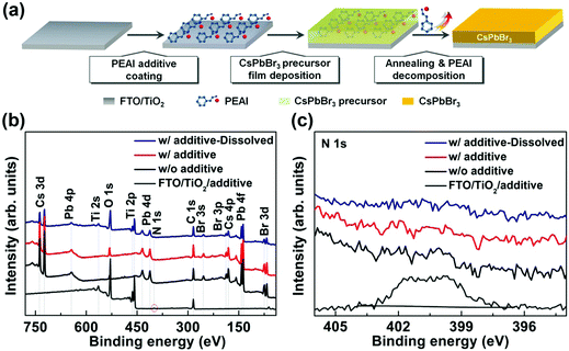
The main steps in preparing the CsPbBr3 film by a sacrificial additive-assisted strategy are illustrated in Fig. 1(a). Firstly, PEAI species was loaded on the FTO/TiO2 substrate by spin-coating PEAI methanol solution. Then, the CsPbBr3 precursor film was deposited via an intermediate phase halide exchange method, as demonstrated previously.31 During this process, the PEAI species on the FTO/TiO2 substrate could be dissolved in dimethyl sulfoxide (DMSO) solvent of the CsPbBr3 precursor and they deposit on the CsPbBr3 precursor film, because of the soluble nature of the PEAI molecules in DMSO.44 Finally, the sample was annealed at 300 °C for 30 min to promote CsPbBr3 film crystallization, during which the escape of the PEAI species occurs simultaneously, as discussed below. The detailed preparation procedures can be found in the Experimental section.X-ray photoelectron spectroscopy (XPS) measurements were conducted to investigate the FTO/TiO2 substrate with loading of PEAI species. As shown in Fig. 1(b) and (c), apart from those of C, Ti, and O elements, an extra peak located at 401.8 eV was detected, which can be assigned to N 1s of PEAI species.45,46 This result verifies the successful loading of PEAI species onto the FTO/TiO2 substrate. Meanwhile, the compositions of CsPbBr3 films synthesized without and with PEAI species were investigated. Clear XPS peaks corresponding to Cs, Pb, and Br elements were detected for both films, revealing that they are composed of CsPbBr3 materials.47,48 Interestingly, there is no detectable signal that relates to PEAI species for the CsPbBr3 film deposited on the FTO/TiO2 substrate with loading of PEAI species, similar to that of the control sample without loading of PEAI species. This fact is also indicated by the core-level N 1s XPS spectra in Fig. 1(c), because the typical core-level N 1s characteristic peak of PEAI species is absent for both CsPbBr3 films.
It is noted that XPS can only detect the surficial composition information of the samples. To probe the bulk composition of the CsPbBr3 film deposited on the FTO/TiO2 substrate with loading of PEAI species, the film was firstly dissolved in DMSO solvent and then was annealed at 100 °C for 5 min to evaporate the solvent. As shown in Fig. 1(b), the additional Ti 2p peaks that come from the FTO/TiO2 substrate appear for the sample after DMSO treatment, disclosing the full dissolution of the CsPbBr3 film and therefore the elimination of the possible non-uniform composition distribution in the film or at its interface. In this case, XPS technology can study the bulk composition of the CsPbBr3 film reasonably. Once again, as shown in Fig. 1(c), the N 1s peak is still absent for the dissolved CsPbBr3 film deposited on the FTO/TiO2 substrate containing PEAI species, further indicating that there is indeed no detectable PEAI species in the resulting CsPbBr3 film. We attribute such an interesting fact to the decomposition of PEAI species during CsPbBr3 film crystallization under high-temperature annealing conditions at 300 °C, since PEAI powder has a decomposition temperature of ∼280 °C in a N2 atmosphere, as demonstrated by Ma et al.49 This is also supported by the thermogravimetric analysis (TGA) and differential scanning calorimetry (DSC) results of PEAI powder in Fig. S1(a) and (b) (ESI†). It can be seen that PEAI powder undergoes 100% weight loss in one step with an onset temperature around 200 °C. Moreover, the TGA curve indicates that the typical decomposition temperature of the PEAI powder is about ∼282 °C. Overall, one can make sense that PEAI species are incorporated before CsPbBr3 film crystallization and then are extracted after its crystallization. They act as a sacrificial additive during CsPbBr3 film growth. Hereafter, the PEAI species are defined as a sacrificial additive to clarify our discussion.
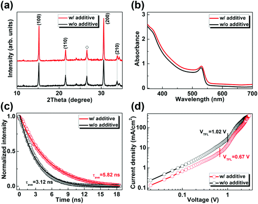
Next, the fundamental physical properties of CsPbBr3 films prepared without and with PEAI sacrificial additive are investigated. Fig. 2(a) shows the XRD results, wherein all the diffraction peaks well coincide those of CsPbBr3 materials with a cubic perovskite phase,32,47 revealing the pure phase of both CsPbBr3 films. By comparison, the diffraction peak intensities of the (100) and (200) crystal planes are somewhat stronger for the CsPbBr3 film prepared with PEAI sacrificial additive, indicating its better crystallinity with fewer inter- and/or intra-grains defects. Fig. 2(b) shows the ultraviolet-visible (UV-vis) absorption spectra of the concerned CsPbBr3 films. Both films exhibit a similar absorption onset of ∼540 nm and an exciton absorption resonance at ∼530 nm, which agree with those of the CsPbBr3 films reported previously.26,43,50 The slightly higher absorption can be identified for the CsPbBr3 film prepared with PEAI sacrificial additive, which is probably related to its higher crystallinity and/or different surficial morphology (as discussed below). Fig. 2(c) shows the time-resolved photoluminescence (TRPL) results of the obtained CsPbBr3 films on insulating glass substrates. The average lifetime (τave) values of the minority carriers are estimated to be 3.12 and 5.82 ns for the CsPbBr3 films prepared without and with PEAI sacrificial additive, respectively. The longer τave for the latter is indicative of the weaker non-radiative recombination of charge carriers, because of fewer defects in it. This inference is further supported by the space-charge-limited current (SCLC) analysis of hole-only dark current density versus voltage (J–V) curves of the prepared CsPbBr3 films,51,52 as shown in Fig. 2(d). Obviously, the CsPbBr3 film synthesized with PEAI sacrificial additive exhibits a much smaller trap-filled limit voltage (VTFL) of 0.67 V, compared with the control sample with a VTFL of 1.02 V. In general, VTFL is connected with trap density (Nt) by the relationship of VTFL = eNtL2/(2εε0), where ε and ε0 are the relative dielectric constant of CsPbBr3 and vacuum permittivity, L is the thickness of the CsPbBr3 film, and e is the elementary charge of the electron, respectively. Therefore, the much smaller hole trap density can be identified for the CsPbBr3 film prepared with PEAI sacrificial additive, which suggests substantially fewer defects in it in turn. In addition, one can see that the CsPbBr3 film prepared with PEAI sacrificial additive exhibits lower J values under bias voltages below 2.5 V, indicative of its lower conductivity.
A scanning electron microscope (SEM) and an atomic force microscope (AFM) were employed to analyze the surficial morphology of the as-prepared CsPbBr3 films. As shown in Fig. 3(a) and (b) and Fig. S2(a) and (b) (ESI†), both films have full surface coverage, regardless of being prepared without and with PEAI sacrificial additive. Moreover, they consist of micro-sized crystal grains with trip-junction grain boundaries and similar average sizes of ∼0.75 μm (Fig. S3, ESI†). However, there seems to be some extra inclusions in the adjoining grains of the CsPbBr3 film formed with PEAI sacrificial additive, since they show relatively bright contrast, possibly because of their less conductive nature.53–55 As with the SEM results, the AFM images in Fig. 3(c) and (d) show similar characters of the CsPbBr3 films. Meanwhile, the root-mean-square (RMS) roughness values were estimated to be 24.3 and 20.6 nm for the CsPbBr3 film prepared without and with PEAI sacrificial additive, respectively. That is to say, the less-conductive inclusions in the CsPbBr3 film prepared with PEAI sacrificial additive do not increase the film's surface roughness, but decrease it. Such a result further indicates that the inclusions cover conformally on the CsPbBr3 grains.
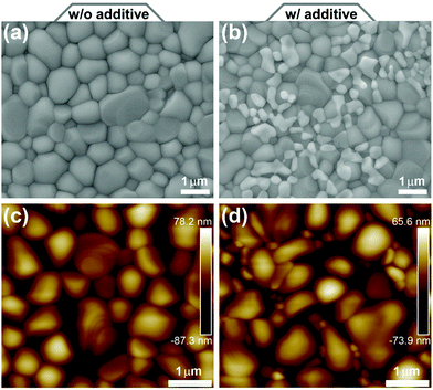 | ||
| Fig. 3 (a and b) SEM and (c and d) AFM images of CsPbBr3 films prepared (a and c) without and (b and d) with PEAI sacrificial additive, respectively. | ||
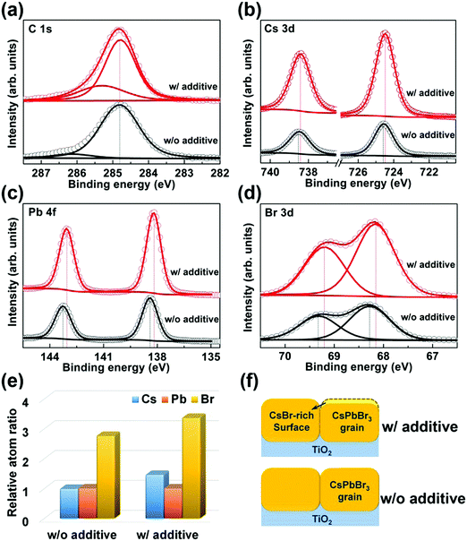
Since XRD does not detect any impurity phase in the CsPbBr3 film prepared with PEAI sacrificial additive, the XPS test is further adopted to gain insight into the less-conductive inclusions observed in Fig. 3(b) and (d). The control sample is also investigated for comparison. All the XPS results are calibrated with the C 1s peak with a binding energy of 284.8 eV, as indicated in Fig. 4(a). Fig. 4(b)–(d) show the corresponding core-level XPS spectra of Cs 3d, Pb 4f, and Br 3d, respectively. These XPS peaks are basically in accordance with previously reported results of CsPbBr3 materials.47,48 By contrast, they shift slightly towards lower binding energies for the CsPbBr3 film prepared with PEAI sacrificial additive, which is probably caused by the less-conductivity inclusions in it. In addition, the atomic ratios of Cs and Br atoms relative to Pb atoms for both CsPbBr3 films are calculated, as shown in Fig. 4(e). The CsPbBr3 film prepared without PEAI sacrificial additive exhibits Cs![[thin space (1/6-em)]](https://www.rsc.org/images/entities/char_2009.gif) :
:![[thin space (1/6-em)]](https://www.rsc.org/images/entities/char_2009.gif) Pb
Pb![[thin space (1/6-em)]](https://www.rsc.org/images/entities/char_2009.gif) :
:![[thin space (1/6-em)]](https://www.rsc.org/images/entities/char_2009.gif) Br atomic ratios of 0.98
Br atomic ratios of 0.98![[thin space (1/6-em)]](https://www.rsc.org/images/entities/char_2009.gif) :
:![[thin space (1/6-em)]](https://www.rsc.org/images/entities/char_2009.gif) 1.00
1.00![[thin space (1/6-em)]](https://www.rsc.org/images/entities/char_2009.gif) :
:![[thin space (1/6-em)]](https://www.rsc.org/images/entities/char_2009.gif) 2.75. However the one formed with PEAI sacrificial additive possesses values of 1.45
2.75. However the one formed with PEAI sacrificial additive possesses values of 1.45![[thin space (1/6-em)]](https://www.rsc.org/images/entities/char_2009.gif) :
:![[thin space (1/6-em)]](https://www.rsc.org/images/entities/char_2009.gif) 1.00
1.00![[thin space (1/6-em)]](https://www.rsc.org/images/entities/char_2009.gif) :
:![[thin space (1/6-em)]](https://www.rsc.org/images/entities/char_2009.gif) 3.36. These results reveal that there are certain CsBr-rich CsPbBr3 crystals in the surface region of the CsPbBr3 film prepared with PEAI sacrificial additive. Therefore, the less-conductive inclusions in the adjoining grains of the CsPbBr3 film are ascribed to CsBr-rich CsPbBr3, as schematically shown in Fig. 4(f). As a whole, the above investigations reveal that PEAI sacrificial additive can induce the formation of the desired CsPbBr3 film with full coverage, pure phase, micro-sized grains, higher crystallinity, fewer defects, and particularly a CsBr-rich surface with lower conductivity.
3.36. These results reveal that there are certain CsBr-rich CsPbBr3 crystals in the surface region of the CsPbBr3 film prepared with PEAI sacrificial additive. Therefore, the less-conductive inclusions in the adjoining grains of the CsPbBr3 film are ascribed to CsBr-rich CsPbBr3, as schematically shown in Fig. 4(f). As a whole, the above investigations reveal that PEAI sacrificial additive can induce the formation of the desired CsPbBr3 film with full coverage, pure phase, micro-sized grains, higher crystallinity, fewer defects, and particularly a CsBr-rich surface with lower conductivity.
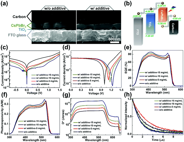
Furthermore, CsPbBr3 films prepared without and with PEAI sacrificial additive are used to build self-powered PDs with the layer stacking of FTO/TiO2/CsPbBr3/carbon. This configuration could enable simplified fabrication procedures and improved stability of the PDs, along with their substantially reduced cost, due to avoiding the use of high-cost, unstable hole transport materials and noble metal electrodes.50,51,56Fig. 5(a) shows the cross-sectional SEM images of typical PDs prepared without and with PEAI sacrificial additive, from which each functional layer can be identified. In particular, the thicknesses of the CsPbBr3 films are estimated to be ∼410 nm similarly. Moreover, one can see that nearly all the individual grains in each CsPbBr3 film can cross the entire film and form vertically oriented grain boundaries, wherein the interfacial voids may be induced by air bubbles in the precursor solution. Fig. 5(b) shows the working mechanism of self-powered CsPbBr3 PD prepared with PEAI sacrificial additive, for which the band energy of CsPbBr3 is determined by the ultraviolet photoelectron spectroscopy (UPS) spectrum in Fig. S4 (ESI†), considering its bandgap of 2.3 eV. Upon light illumination, photo-generated electrons are extracted by the TiO2 layer and then are collected by the FTO electrode, while photo-generated holes are extracted and collected by the carbon electrode, due to the favored energy alignments. Thus, the optical signals are converted into electrical signals. It is noted that the PEAI solution at different concentrations of 5, 10, and 15 mg mL−1 are employed in this section, aiming to optimize the performance of PDs fabricated with PEAI sacrificial additive.
Fig. 5(c) provides dark J–V curves of all the fabricated CsPbBr3 PDs. The PDs prepared with PEAI sacrificial additive show much smaller dark current densities, in particular the one prepared with 10 mg mL−1 PEAI solution. For example, at 0.5 V bias voltage, the PD prepared without PEAI sacrificial additive exhibits a dark current density of 1.40 × 10⁻⁴ A cm−2, while the value is reduced significantly to 1.87 × 10⁻⁶ A cm−2 for the one fabricated with PEAI sacrificial additive (10 mg mL−1). Meanwhile, the latter exhibits a minimum dark current density of 8.05 × 10⁻¹¹ A cm−2, which is lower than almost all of previously reported self-powered CsPbBr3 PDs.14,18,23,27,31,36,38,40 Such a low dark current can be primarily ascribed to the unique CsBr-rich surface for CsPbBr3 prepared with PEAI sacrificial additive, which has low conductivity. A lower dark current is generally coupled with a smaller shot noise and a lower thermal noise, which could endow a PD with higher sensitivity.14,31 Under illumination and a bias voltage of 0 V, all the PDs yield greatly enlarged current densities (Fig. 5(d)), indicating their functionality of self-powered photoresponse. The open-circuit voltage (Voc) for self-powered CsPbBr3 PD fabricated without PEAI sacrificial additive is estimated to be 1.00 V. By contrast, such values are boosted greatly to 1.12, 1.24, and 1.16 V for the ones obtained with PEAI sacrificial additive, when the concentrations of the PEAI solution are 5, 10, and 15 mg mL−1, respectively. The improved Voc indicates the recued non-radiative recombination of charge carriers in the self-powered CsPbBr3 PDs.51,57Fig. 5(e) shows the external quantum efficiency (EQE) spectra of all the fabricated PDs. Their photocurrent generation starts at ∼540 nm, disclosing that CsPbBr3 films govern their photoelectric conversion. Furthermore, the R spectra and D* curves of all the PDs obtained without and with PEAI sacrificial additive are calculated and provided in Fig. 5(f) and (g). There is an obvious fact that self-powered CsPbBr3 PDs prepared with PEAI sacrificial additive exhibit much higher R and D* values in contrast to the one fabricated without that. Moreover, when the concentration of the PEAI solution is optimized to 10 mg mL−1, the PD yields the best R and D* values with a maximum R of 0.35 A W−1 and a D* of 3.83 × 10¹³ Jones, respectively. Fig. 5(h) shows the transient photocurrent (TPC) curves for all the prepared self-powered CsPbBr3 PDs. Their response time values can be obtained by fitting the curves with a single-exponential decay function of time.14,58 By this way, the response time of the PD fabricated without PEAI sacrificial additive is estimated to be 2.74 μs. The values decrease to 2.20, 1.46, and 1.59 μs for the ones fabricated with 5, 10, and 15 mg mL−1 PEAI solution, respectively. Therefore, the fast response of self-powered PDs fabricated with PEAI sacrificial additive can be identified, particularly when 10 mg mL−1 PEAI solution is adopted. Overall, the PEAI sacrificial additive-assisted film growth strategy can endow self-powered CsPbBr3 PD with a minimum dark current density of 8.05 × 10⁻¹¹ A cm−2, a maximum R of 0.35 A W−1, a D* peak of 3.83 × 10¹³ Jones, and a response time of 1.46 μs, most of which are better than self-powered CsPbBr3 PDs reported previously,14,18,23,27,29–31,34–36,38,40 as summarized in Table 1.
| PD configuration | Dark current @ bias | R (A W−1) | D* (Jones) | Falling time | Ref. |
|---|---|---|---|---|---|
| FTO/TiO2/CsPbBr3/carbon | 8.05 × 10⁻¹¹ A cm−2 @ 0 V | 0.35 | 3.83 × 10¹³ | 1.46 μs | This work |
| ITO/CsPbBr3:ZnO/Ag | 0.240 A cm−2 @ 0 V | 0.0115 | — | 0.0179 s | 18 |
| FTO/ZnO/CsPbBr3/MoO3/Au | — | 0.3 | 1.15 × 10¹³ | 500 ms | 34 |
| FTO/Al2O3/CsPbBr3/TiO2/Au | 10 nA | 0.44 | 1.88 × 10¹³ | 270 μs | 36 |
| FTO/TiO2/CsPbBr3/carbon | 8.7 × 10⁻⁸ A cm−2 @ −0.3 V | 0.35 | 1.94 × 10¹³ | 0.58 μs | 31 |
| ITO/PTAA + PEIE/CsPbBr3/PCBM/BCP/Ag | 4.8 × 10⁻⁸ A cm−2 @ 0.3 V | 0.13 | 6.0 × 10¹² | 62 ns | 14 |
| Au/CsPbBr3/Pt | 10 pA @ 0 V | 0.028 | 1.7 × 10¹¹ | 60 ms | 23 |
| Ag/CsPbBr3/CuI/Ag | — | 0.0014 | 6.2 × 10¹⁰ | 2.96 ms | 30 |
| ITO/SnO2/CsPbBr3/Spiro-OMeTAD/Au | <10 nA | 0.172 | 4.8 × 10¹² | 0.12 ms | 40 |
| ITO/SnO2/CsPbBr3/PTAA/Au | 2.5 × 10⁻⁹ A cm−2 | 0.206 | 7.23 × 10¹² | 39 μs | 38 |
| GaN/CsPbBr3/ZnO | 1 × 10⁻⁹ A cm−2 | 0.0895 | 1.03 × 10¹⁴ | 140 μs | 35 |
| ITO/SnO2/PMMA + CsPbBr3/PTAA/Au | 4.0 × 10⁻⁹ A cm−2 @ 0 V | 0.3 | 1 × 10¹³ | 0.43 ms | 27 |
| In/SnO2/CsPbBr3/In | 2 pA | 0.01 | 2.6 × 10¹¹ | 1.94 ms | 29 |
In addition, carrier dynamics in self-powered CsPbBr3 PDs fabricated without and with PEAI sacrificial additive are investigated to understand the better performance of the latter in depth. Fig. 6(a) shows the re-plotted Mott–Schottky (M–S) results of two typical PDs, from which the built-in potential (Vbi) values are estimated to be 1.38 and 1.51 V for the PDs fabricated without and with PEAI sacrificial additive, respectively.51,56,59 The larger Vbi could promote more effective extraction and separation of photo-generated carriers and thus reduces the carrier recombination in the latter one. Fig. 6(b) shows the corresponding Nyquist plots under a bias voltage of 1 V and dark conditions. The obvious arc is ascribed to the recombination of photo-generated carriers, reflecting the recombination resistance (Rrec), as indicated by the equivalent circuit model in Fig. S5 (ESI†).51,56,59 The PD fabricated with PEAI sacrificial additive yields a larger Rrec than that without PEAI, indicative of a weaker carrier recombination. Therefore, we can infer that the superior performance of the self-powered CsPbBr3 PD fabricated with PEAI sacrificial additive is largely related to the reduced recombination of photo-generated carriers in it, which originally benefits from the desired features of the CsPbBr3 film, in particular its higher crystallinity, fewer defects, and a CsBr-rich surface with lower conductivity.
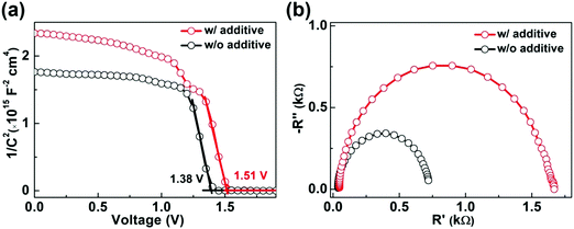 | ||
| Fig. 6 (a) C−2–V results under dark conditions and (b) Nyquist plots for the optimized self-powered CsPbBr3 PD fabricated without and with PEAI sacrificial additive, respectively. | ||
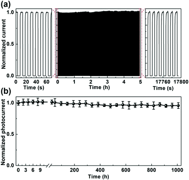
Finally, the operational reliability and long-term stability of the optimized self-powered CsPbBr3 PD fabricated with PEAI sacrificial additive are investigated primarily, which are carried out on an unencapsulated device in ambient air atmosphere with a relative humidity (RH) of 40–50% and a temperature of ∼25 °C. Fig. 7(a) shows its response to a 405 nm on/off modulated laser. One can see that both the dark current and the photocurrent show little variations over the whole test period of ∼5 h, indicating the excellent operational reliability of self-powered CsPbBr3 PD fabricated with PEAI sacrificial additive. Fig. 7(b) shows time-dependent variations of normalized photocurrents for the same PD. One can make sense that it delivers a stable photocurrent over ∼1000 h. About 96% of its initial photocurrent can be maintained after this test period. The above results demonstrate the excellent operational reliability and long-term stability of the self-powered CsPbBr3 PD fabricated with PEAI sacrificial additive.
3. Conclusions
In summary, we report for the first time the preparation of the CsPbBr3 film by a PEAI sacrificial additive-assisted strategy for self-powered PDs. The CsPbBr3 film possesses full coverage, a pure phase, micro-sized grains, higher crystallinity, fewer defects, and particularly a CsBr-richer surface that has a lower conductivity, in contrast with that prepared without PEAI sacrificial additive. The resulting self-powered PD with a simple configuration of FTO/TiO2/CsPbBr3/carbon exhibits a minimum dark current density of 8.05 × 10⁻¹¹ A cm−2, a peak R of 0.35 A W−1, a peak D* of 3.83 × 10¹³ Jones, and a response time of 1.46 μs. They are much better than the one prepared without PEAI sacrificial additive and are even beyond most self-powered CsPbBr3 PDs reported previously. The mechanism underlying the superior performance of the self-powered CsPbBr3 PD fabricated with PEAI sacrificial additive is explored and mainly attributed to the much reduced recombination of photo-generated carriers. In addition, we demonstrate the excellent operational reliability and long-term stability of the self-powered CsPbBr3 PD in an ambient air atmosphere. Hence, our study suggests a simple and robust protocol for developing high-performance, stable CsPbBr3 PDs for potential practical applications.4. Experimental section
Reagents and materials
Ultradry PbBr2 (99.999%, Alfa Aesar), ultradry CsI (99.998%, Alfa-Aesar), PEAI (≥99.5%, Xi'an Polymer Light Technology Corp.), CH3NH3Br (≥99.5%, Xi'an Polymer Light Technology Corp.), anhydrous methanol (99.9%, Alfa-Aesar), DMSO (ACS reagent, ≥99.9%, Sigma-Aldrich), conductive carbon paste (ZF-G03-04-2, Shanghai MaterWin New Materials Co., Ltd), and FTO glass (TEC8, 8 Ω sq−1, Pilkington TEC Glass) were purchased and used as received unless otherwise noted.Preparation of the CsPbBr3 film
100 μL of TiO2 sol was spin-coated onto a pre-cleaned FTO substrate at 3500 rpm for 30 s, which was further annealed at 500 °C for 60 min in ambient air. After cooling down to room temperature naturally, the FTO/TiO2 substrate can be prepared. The CsPbBr3 film was then coated on it by an intermediate phase halide exchange method. To be specific, 100 μL precursor solution obtained by pre-dissolving 370 mg PbBr2 and 260 mg CsI into 1 mL DMSO was dipped onto the FTO/TiO2 substrate, which was followed by spin-coating at 3500 rpm for 30 s and 5000 rpm for 120 s. After this, 60 μL CH3NH3Br methanol solution with a concentration of 20 mg mL−1 was spin-coated onto it at 5000 rpm for 30 s. Thus, the CsPbBr3 precursor film can be obtained. After being annealed at 300 °C for 30 min, the crystalline CsPbBr3 film was achieved.Fabrication of self-powered CsPbBr3 PD
A carbon back-electrode with an active area of 0.085 cm2 was loaded onto the CsPbBr3 film using screen-printing commercial conductive carbon paste. After thermal treatment at 120 °C for 15 min, a self-powered CsPbBr3 PD can be obtained.Characterization
The XPS/UPS spectra were acquired using a photoelectron spectrometer (VG Multilab 2000×, Thermo Electron Corp., Waltham, MA, USA). The TGA and DSC curves were recorded using a STA 409 PC Luxx thermal analyser (NETZSCH, Germany) with a heating rate of 10 °C min−1. The XRD patterns were tested using a Bruker D8 Advance powder X-ray diffractometer and Cu Kα radiation (1.5406 Å). The UV-vis absorption spectra were recorded using a spectrophotometer (U-4100, Hitachi). The TRPL spectra were obtained using a time-resolved single photon-counting setup (FluoTime 300, PicoQuant). The SEM images were obtained by high-resolution SEM (JEOL-7100F). The AFM images were tested using a Bruker Dimension FastScan AFM. The J–V curves were measured using a Keithley 2636 source meter. The EQE spectra were collected using a Zolix DSR-101-UV system equipped with a Si PD as reference. The R curves of the PDs can be obtained using the following formula: , where λ is the wavelength, h is the Planck constant, c is the light speed, and e is the elementary charge. D* spectra can be calculated using the followed equation:
  , where A is the device working area, e is the elementary charge and Id is the measured minimum dark current. The TPC curves were recorded using a digital oscilloscope (Tektronix, MSO5204B) with an input resistance of 50 Ω, where the device was illuminated with a 520 nm pulse laser (MDL-NS-520). EIS measurements were performed on an electrochemical workstation (CHI600E, Shanghai Chenhua) with 10 mV amplitude perturbation. M–S plots were obtained using the same system with an AC excitation amplitude of 30 mV at a frequency of 5 kHz. Stability curves of PDs were recorded using a Keithley 2636B source meter, during which the device was illuminated with a 405 nm CW laser (MDL-III-405) modulated by a square signal (100 mHz, 10 s) generated by an arbitrary function generator (Tektronix, AFG3051C). All the measurements of PD performance were conducted in an ambient air atmosphere with a RH of 40–50% and a temperature of ∼25 °C.
Conflicts of interest
There are no conflicts to declare.Acknowledgements
All the authors gratefully acknowledge the financial support from the National Natural Science Foundation of China (61804113, 61704128, and 61874083), the Initiative Postdocs Supporting Program (BX20190261), and the National Natural Science Foundation of Shaanxi Province (2018ZDCXL-GY-08-02-02 and 2017JM6049).References
- J. S. Manser, J. A. Christians and P. V. Kamat, Chem. Rev., 2016, 116, 12956–13008 CrossRef CAS.
- W. J. Yin, T. Shi and Y. Yan, Adv. Mater., 2014, 26, 4653–4658 CrossRef CAS.
- K. Chen, S. Schünemann, S. Song and H. Tüysüz, Chem. Soc. Rev., 2018, 47, 7045–7077 RSC.
- M. Saliba, J. P. Correa-Baena, M. Grätzel, A. Hagfeldt and A. Abate, Angew. Chem., Int. Ed., 2018, 57, 2554–2569 CrossRef CAS PubMed.
- Z. Li, T. R. Klein, D. H. Kim, M. Yang, J. J. Berry, M. F. van Hest and K. Zhu, Nat. Rev. Mater., 2018, 3, 18017 CrossRef CAS.
- Y. Rong, Y. Hu, A. Mei, H. Tan, M. I. Saidaminov, S. I. Seok, M. D. McGehee, E. H. Sargent and H. Han, Science, 2018, 361, eaat8235 CrossRef.
- A. Kojima, K. Teshima, Y. Shirai and T. Miyasaka, J. Am. Chem. Soc., 2009, 131, 6050–6051 CrossRef CAS.
- Cell efficiency chart, https://www.nrel.gov/pv/cell-efficiency.html, accessed: August 2019.
- L. Dou, Y. M. Yang, J. You, Z. Hong, W.-H. Chang, G. Li and Y. Yang, Nat. Commun., 2014, 5, 5404 CrossRef CAS.
- H. Wang and D. H. Kim, Chem. Soc. Rev., 2017, 46, 5204–5236 RSC.
- M. Ahmadi, T. Wu and B. Hu, Adv. Mater., 2017, 29, 1605242 CrossRef.
- Y. Zhao, C. Li and L. Shen, InfoMat, 2019, 1, 164–182 CrossRef.
- Y. Yan, Q. Wu, Y. Zhao, S. Chen, S. Hu, J. Zhu, J. Huang and Z. Liang, Small, 2018, 14, 1802764 CrossRef.
- C. Bao, J. Yang, S. Bai, W. Xu, Z. Yan, Q. Xu, J. Liu, W. Zhang and F. Gao, Adv. Mater., 2018, 30, 1803422 CrossRef.
- J. Deng, J. Li, Z. Yang and M. Wang, J. Mater. Chem. C, 2019, 7, 12415–12440 RSC.
- A. Fakharuddin, U. Shabbir, W. Qiu, T. Iqbal, M. Sultan, P. Heremans and L. Schmidt-Mende, Adv. Mater., 2019, 1807095 CrossRef CAS PubMed.
- Z. Wang, Z. Shi, T. Li, Y. Chen and W. Huang, Angew. Chem., Int. Ed., 2017, 56, 1190–1212 CrossRef CAS.
- C. Li, C. Han, Y. Zhang, Z. Zang, M. Wang, X. Tang and J. Du, Sol. Energy Mater. Sol. Cells, 2017, 172, 341–346 CrossRef CAS.
- M. Shoaib, X. Zhang, X. Wang, H. Zhou, T. Xu, X. Wang, X. Hu, H. Liu, X. Fan and W. Zheng, J. Am. Chem. Soc., 2017, 139, 15592–15595 CrossRef CAS.
- J. Ding, S. Du, Z. Zuo, Y. Zhao, H. Cui and X. Zhan, J. Phys. Chem. C, 2017, 121, 4917–4923 CrossRef CAS.
- Y. Dong, Y. Gu, Y. Zou, J. Song, L. Xu, J. Li, J. Xue, X. Li and H. Zeng, Small, 2016, 12, 5622–5632 CrossRef CAS.
- Y. Li, Z.-F. Shi, S. Li, L.-Z. Lei, H.-F. Ji, D. Wu, T.-T. Xu, Y.-T. Tian and X.-J. Li, J. Phys. Chem. C, 2017, 5, 8355–8360 CAS.
- M. I. Saidaminov, M. A. Haque, J. Almutlaq, S. Sarmah, X. H. Miao, R. Begum, A. A. Zhumekenov, I. Dursun, N. Cho and B. Murali, Adv. Opt. Mater., 2017, 5, 1600704 CrossRef.
- Z. Yang, Q. Xu, X. Wang, J. Lu, H. Wang, F. Li, L. Zhang, G. Hu and C. Pan, Adv. Mater., 2018, 30, 1802110 CrossRef.
- Y. Li, Z. Shi, L. Lei, F. Zhang, Z. Ma, D. Wu, T. Xu, Y. Tian, Y. Zhang and G. Du, Chem. Mater., 2018, 30, 6744–6755 CrossRef CAS.
- G. Tong, H. Li, D. Li, Z. Zhu, E. Xu, G. Li, L. Yu, J. Xu and Y. Jiang, Small, 2018, 14, 1702523 CrossRef PubMed.
- H. Zhou, Z. Song, C. R. Grice, C. Chen, J. Zhang, Y. Zhu, R. Liu, H. Wang and Y. Yan, Nano Energy, 2018, 53, 880–886 CrossRef CAS.
- Y. Shen, C. Wei, L. Ma, S. Wang, X. Wang, X. Xu and H. Zeng, J. Mater. Chem. C, 2018, 6, 12164–12169 RSC.
- Y. Zhang, W. Xu, X. Xu, J. Cai, W. Yang and X. Fang, J. Phys. Chem. Lett., 2019, 10, 836–841 CrossRef CAS.
- Y. Zhang, S. Li, W. Yang, M. K. Joshi and X. Fang, J. Phys. Chem. Lett., 2019, 10, 2400–2407 CrossRef CAS PubMed.
- W. Zhu, M. Deng, Z. Zhang, D. Chen, H. Xi, J. Chang, J. Zhang, C. Zhang and Y. Hao, ACS Appl. Mater. Interfaces, 2019, 11, 22543–22549 CrossRef CAS PubMed.
- J. Zeng, X. Li, Y. Wu, D. Yang, Z. Sun, Z. Song, H. Wang and H. Zeng, Adv. Funct. Mater., 2018, 28, 1804394 CrossRef.
- Z. L. Wang, Adv. Mater., 2012, 24, 280–285 CrossRef CAS.
- M. Xue, H. Zhou, G. Ma, L. Yang, Z. Song, J. Zhang and H. Wang, Sol. Energy Mater. Sol. Cells, 2018, 187, 69–75 CrossRef CAS.
- C. Tian, F. Wang, Y. Wang, Z. Yang, X. Chen, J. Mei, H. Liu and D. Zhao, ACS Appl. Mater. Interfaces, 2019, 11, 15804–15812 CrossRef CAS.
- G. Cen, Y. Liu, C. Zhao, G. Wang, Y. Fu, G. Yan, Y. Yuan, C. Su, Z. Zhao and W. Mai, Small, 2019, 1902135 CrossRef.
- K. Shen, X. Li, H. Xu, M. Wang, X. Dai, J. Guo, T. Zhang, S. Li, G. Zou and K.-L. Choy, J. Mater. Chem. A, 2019, 7, 6134–6142 RSC.
- H. Zhou, Z. Song, C. R. Grice, C. Chen, X. Yang, H. Wang and Y. Yan, J. Phys. Chem. Lett., 2018, 9, 4714–4719 CrossRef CAS.
- H. Zhou, L. Fan, G. He, C. Yuan, Y. Wang, S. Shi, N. Sui, B. Chen, Y. Zhang and Q. Yao, RSC Adv., 2018, 8, 29089–29095 RSC.
- H. Zhou, J. Zeng, Z. Song, C. R. Grice, C. Chen, Z. Song, D. Zhao, H. Wang and Y. Yan, J. Phys. Chem. Lett., 2018, 9, 2043–2048 CrossRef CAS.
- B. Yang, F. Zhang, J. Chen, S. Yang, X. Xia, T. Pullerits, W. Deng and K. Han, Adv. Mater., 2017, 29, 1703758 CrossRef.
- F. Jin, B. Zhao, B. Chu, H. Zhao, Z. Su, W. Li and F. Zhu, J. Mater. Chem. C, 2018, 6, 1573–1578 RSC.
- L. Zhang, F. Yuan, H. Dong, B. Jiao, W. Zhang, X. Hou, S. Wang, Q. Gong and Z. Wu, ACS Appl. Mater. Interfaces, 2018, 10, 40661–40671 CrossRef CAS.
- K. Wang, Z. Jin, L. Liang, H. Bian, D. Bai, H. Wang, J. Zhang, Q. Wang and L. Shengzhong, Nat. Commun., 2018, 9, 4544 CrossRef.
- Y. Wang, T. Zhang, M. Kan, Y. Li, T. Wang and Y. Zhao, Joule, 2018, 2, 2065–2075 CrossRef CAS.
- Q. Jiang, Y. Zhao, X. Zhang, X. Yang, Y. Chen, Z. Chu, Q. Ye, X. Li, Z. Yin and J. You, Nat. Photonics, 2019, 13, 460–466 CrossRef CAS.
- Y. Li, Z.-F. Shi, S. Li, L.-Z. Lei, H.-F. Ji, D. Wu, T.-T. Xu, Y.-T. Tian and X.-J. Li, J. Mater. Chem. C, 2017, 5, 8355–8360 RSC.
- X. Zhang, B. Xu, J. Zhang, Y. Gao, Y. Zheng, K. Wang and X. W. Sun, Adv. Funct. Mater., 2016, 26, 4595–4600 CrossRef CAS.
- D. Thrithamarassery Gangadharan, Y. Han, A. Dubey, X. Gao, B. Sun, Q. Qiao, R. Izquierdo and D. Ma, Sol. RRL, 2018, 2, 1700215 CrossRef.
- J. Duan, Y. Zhao, B. He and Q. Tang, Angew. Chem., Int. Ed., 2018, 57, 3787–3791 CrossRef CAS.
- Q. Zhang, W. Zhu, D. Chen, Z. Zhang, Z. Lin, J. Chang, J. Zhang, C. Zhang and Y. Hao, ACS Appl. Mater. Interfaces, 2018, 11, 2997–3005 CrossRef PubMed.
- W. Zhu, L. Kang, T. Yu, B. Lv, Y. Wang, X. Chen, X. Wang, Y. Zhou and Z. Zou, ACS Appl. Mater. Interfaces, 2017, 9, 6104–6113 CrossRef CAS PubMed.
- Q. Chen, H. Zhou, T.-B. Song, S. Luo, Z. Hong, H.-S. Duan, L. Dou, Y. Liu and Y. Yang, Nano Lett., 2014, 14, 4158–4163 CrossRef CAS PubMed.
- Q. Ma, S. Huang, S. Chen, M. Zhang, C. F. J. Lau, M. N. Lockrey, H. K. Mulmudi, Y. Shan, J. Yao and J. Zheng, J. Phys. Chem. C, 2017, 121, 19642–19649 CrossRef CAS.
- L. A. Frolova, Q. Chang, S. Y. Luchkin, D. Zhao, A. F. Akbulatov, N. N. Dremova, A. V. Ivanov, E. E. Chia, K. J. Stevenson and P. A. Troshin, J. Mater. Chem. C, 2019, 7, 5314–5323 RSC.
- W. Zhu, Q. Zhang, D. Chen, Z. Zhang, Z. Lin, J. Chang, J. Zhang, C. Zhang and Y. Hao, Adv. Energy Mater., 2018, 8, 1802080 CrossRef.
- J. Chen and N. G. Park, Adv. Mater., 2018, 1803019 Search PubMed.
- J. Yang, C. Bao, W. Ning, B. Wu, F. Ji, Z. Yan, Y. Tao, J. M. Liu, T. C. Sum and S. Bai, Adv. Opt. Mater., 2019, 1801732 CrossRef.
- F. Cao, L. Meng, M. Wang, W. Tian and L. Li, Adv. Mater., 2019, 31, 1806725 CrossRef PubMed.
Footnotes |
| † Electronic supplementary information (ESI) available. See DOI: 10.1039/c9tc05403k |
| ‡ The authors contributed equally to this work. |
| This journal is © The Royal Society of Chemistry 2020 |

