
Flexible, low-cost and scalable, nanostructured conductive paper-based, efficient hygroelectric generator†
Kelly S.
Moreira
a,
Diana
Lermen
a,
Leandra P.
dos Santos
b,
Fernando
Galembeck
 b and
Thiago A. L.
Burgo
*ac
b and
Thiago A. L.
Burgo
*ac
aDepartment of Chemistry, Federal University of Santa Maria, Santa Maria, RS 97105-900, Brazil. E-mail: thiago.burgo@ufsm.br
bInstitute of Chemistry, University of Campinas, Campinas, SP 13083-970, Brazil
cDepartment of Physics, Federal University of Santa Maria, Santa Maria, RS 97105-900, Brazil
First published on 25th November 2020
Abstract
Electric energy harvesting mediated by atmospheric humidity was first demonstrated in 2010, followed by the description of different approaches by many authors. Moisture-based energy-harvesting devices usually contain metals and/or are fabricated using nanomaterials and lithographic processes. Here we present a flexible energy harvesting device that is an asymmetric capacitor, formed by two electrodes made out of Kraft paper coated with exfoliated and reassembled graphite (ERG). The electrodes are doped with different chemicals and finished using standard papermaking processes. The voltage output of a single ERG-based hygroelectric generator (ERG-HEG) cell is as high as 0.5 V and it can deliver 250 nA of electric current through a 2 MΩ resistor, for days. The voltage and current outputs can be scaled up by connecting ERG-HEGs in series or parallel. Energy harvesting is also achieved by short (5 seconds) cyclic capacitor charge/discharge extending for more than two weeks. Examinaton of the electrodes during their operation, using Kelvin probe and microscopy analysis, showed that negative charge carriers are the main actors in the ERG-HEG devices. The low material cost, the simple fabrication processes and the energy output invite further development and scaling-up of this “green” alternative for producing electricity.
Introduction
The atmosphere has long been recognized as a source and sink of electric power.1,2 Volta, Faraday, Kelvin, Lenard, and others demonstrated that water (liquid, solid or vapor) electrifies during phase changes, in both natural and anthropic environments.3–8 Despite the paramount importance of atmospheric electricity in the global electric circuit and in striking atmospheric phenomena,9–12 the first publication of experimental results on charge harvesting from atmospheric moisture is very recent.13Moisture-enabled electricity generation (also named hygroelectricity) was first demonstrated as an energy source using a combination of isolated metals, with different capabilities to adsorb water ions, thus forming self-charging, asymmetric capacitors.13,14 The partitioning of adsorbed ions is determined by the Brønsted acid–base properties of the oxidized metal surfaces: hydronium ions adsorb on basic sites, while hydroxide ions adsorb on acidic sites.15,16 For instance, aluminum acquires negative charge, while stainless steel becomes positive.13 These results were recently verified and extended to other systems, including field experiments.17 However, most metals undergo corrosion in the environment, which may prevent widespread use of hygroelectric power devices,1,2 leading many researchers to examine alternatives to metals.18–22
Graphene, graphene oxide (GO) and reduced graphene oxide (rGO) have been explored in different ways, since they present a suitable combination of electrical, mechanical and adsorptive properties.23–28 Zhao et al. developed a hygroelectric generator constituted of a GO film with an oxygen gradient. Using a moisture-electric annealing strategy, they observed an output voltage of roughly 20 mV and a power density of 0.42 μW cm−2 when exposed to moisture variation of 30% ΔRH.29 Moreover, increasing the surface area with GO frameworks30 facilitates the diffusion of water vapor within the electrode, increasing the voltage to 0.3 V and power density to 1 mW cm−2. Protein nanowires were also used,31 producing ca. 0.5 volts and ca. 5 μW cm−2 current density with a continuous electric output. This is an important advantage over other competing devices that produce only intermittent bursts of energy, shorter than 50 s.32 Other interesting hygroelectric devices have been described, but based on expensive materials (e.g. gold or platinum), and/or time-consuming fabrication processes.29,32
In this work, we report a low-cost hygroelectric generator (HEG) made using Kraft paper coated with exfoliated and reassembled graphite (ERG) that is made using a scalable process33 from widely available commodities, cellulose and graphite. The first is made from renewable sources while the second is a mineral, but it can be replaced by conductive carbon made from urban garbage by pyrolysis. ERG is formed by aligned sheets of nanographite held together by adsorbed cellulose, which also accounts for its adhesion to various flexible or rigid substrates, including paper.33 Different from the graphene types used by other authors, ERG is a 2D macroscopic material (currently made in 1 m2 sheets) without any basic limitations to scaling-up. Moreover, it is amenable to fabrication by roll-to-toll processes, reaching the high areas needed for higher power output, at low cost. ERG doping with inexpensive but highly active agents is easily done, as shown in the present work. The ERG-HEG shows competitive output, even under low relative humidity, that persists for thousands of capacitor charge–discharge cycles.
Fig. 1a illustrates all the steps of the device fabrication procedure. The Kamide procedure34 was followed to prepare the alkaline cellulose solutions used to exfoliate graphite,35 yielding dispersions of hydrophilic lamellae down to 20 nm thickness with a lateral dimension in the micrometer range. The dispersions were painted on Kraft paper and allowed to dry, yielding flexible paper sheets coated with an adherent layer of exfoliated and reassembled graphite (ERG). The ERG-HEG device is mounted by assembling two coated paper sheets, back-to-back: one was calendered, the other was not. This was further modified by wetting the coated paper with Fe2(SO4)3 or NaOH aqueous solutions and drying under air (50% RH). These two paper dopants were chosen for their respective basic and acidic behavior. The dry sample S1 has a rough aspect that is maintained after wetting with NaOH and drying, to obtain S1-M. The S2 samples have smooth surfaces and S2-M has a brownish aspect due to iron(III) oxohydroxides formed by the hydrolysis of Fe2(SO4)3 (see the ESI,† Sections S1.1 and S1.2, for experimental details and Fig. S1 for pictures of the electrodes). The modified devices are named here m-ERG-HEG (see the ESI,† Section S1.3). They can be described as asymmetric capacitors whose plates are made from soft materials.
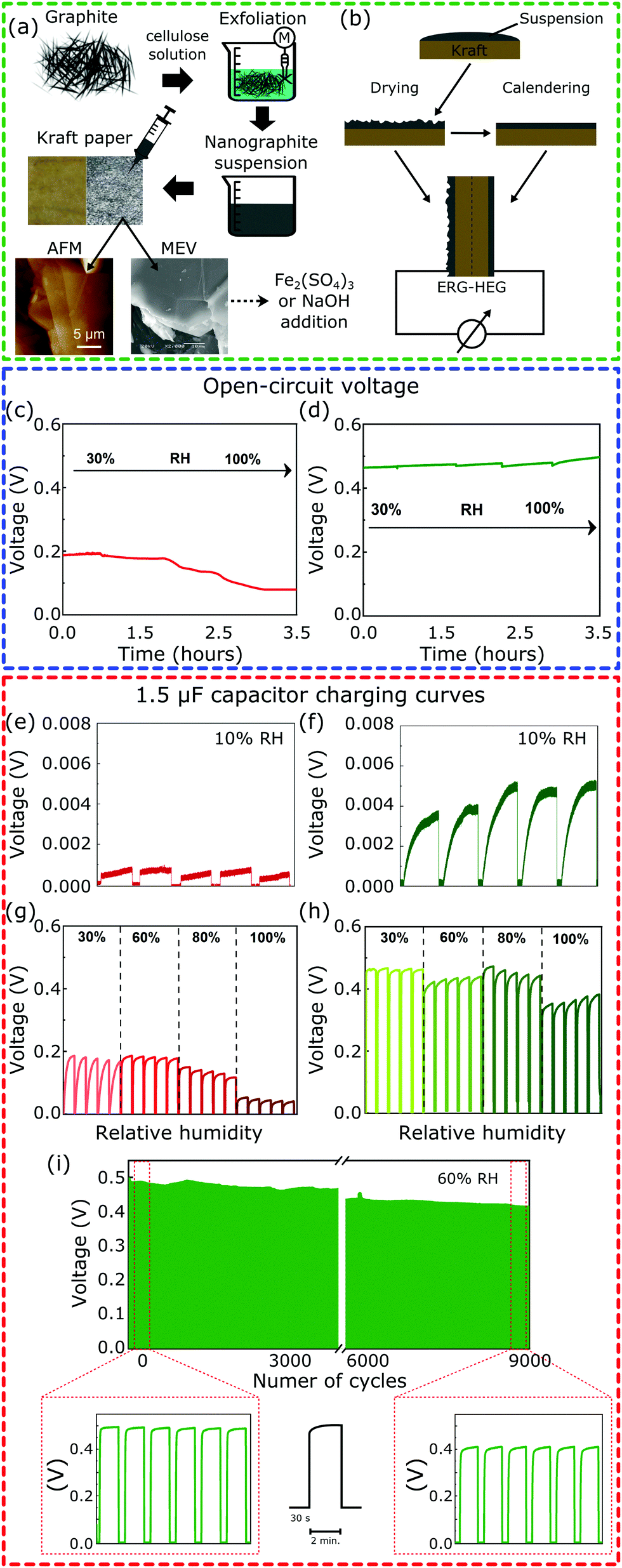 | ||
| Fig. 1 (a) Preparation of a nanostructured carbon paper-based material and (b) schematic illustration of the hygroelectric generator (ERG-HEG) prototype made using two sheets of conductive Kraft paper, with one side just dried and the second one calendered after drying. Open-circuit voltage of the (c) unmodified and (d) modified ERG-HEG under different RHs. Charging/discharging cycles of a 1.5 μF capacitor for the (e and g) unmodified and (f and h) modified ERG-HEG directly connected to a 1.5 μF capacitor. (i) Voltage vs. time of the capacitor undergoing repeated charge/discharge cycles, under 60% RH. | ||
Fig. 1c and d show the open-circuit voltage for the ERG-HEG device, under different RHs (see the ESI,† Sections S1.4 and S1.5, for experimental details). The output voltage is 0.2 V at 30% RH, comparable to other devices found in the literature18 and listed in Table S1 (ESI†), but it decreases down to 0.1 V for RH > 80%. On the other hand, the m-ERG-HEG has an output voltage in the 0.45–0.50 V range, showing little dependence on RH from 30% up. However, the output is negligible at RH = 10%.
The ERG-HEG devices were used to charge common capacitors. Fig. 1e–i show the voltage in a 1.5 μF capacitor that was repeatedly charged and discharged by the hygroelectric device (see also Fig. S3, ESI†). For unmodified and modified ERG-HEG devices under 10% RH, the capacitor voltages are very low, as seen in Fig. 1e and f, but the exposure to 30% to 60% RH raises the capacitor voltage by two orders of magnitude, reaching 0.2 V in the unmodified HEG and 0.50 V in the m-ERG-HEG. Capacitor charging takes only 5 s and the maximum voltage decreases under 100% RH, probably due to current leakage between the capacitor leads.
The m-ERG-HEG performance deteriorates slowly and a ca. 20% lower voltage is recorded after 9000 charge–discharge cycles, extending for >15 days of continuous operation. This is a positive feature of these devices, showing that a steady energy output is obtained within a broad range of RH values that are easily found in natural and human environments.
To better understand the mechanism of the ERG-HEG response to the environmental humidity, the S1, S2, S1-M and S2-M ERG surfaces were scanned with a Kelvin probe under 10 and 80% RH. Fig. 2a shows the surface potential maps (top) and linescans (bottom) from the central part of the maps. The surface potentials of other electrodes were also scanned and their maps are shown in Fig. S4 (ESI†). The surface potential always becomes more negative under high humidity and this effect is more pronounced in S2-M than in the other samples. The average differences between nine selected spots in the linescans from the pair S2-M/S1-M under 80 and 10% RH are respectively 0.45 ± 0.09 and 0.21 ± 0.09 V.
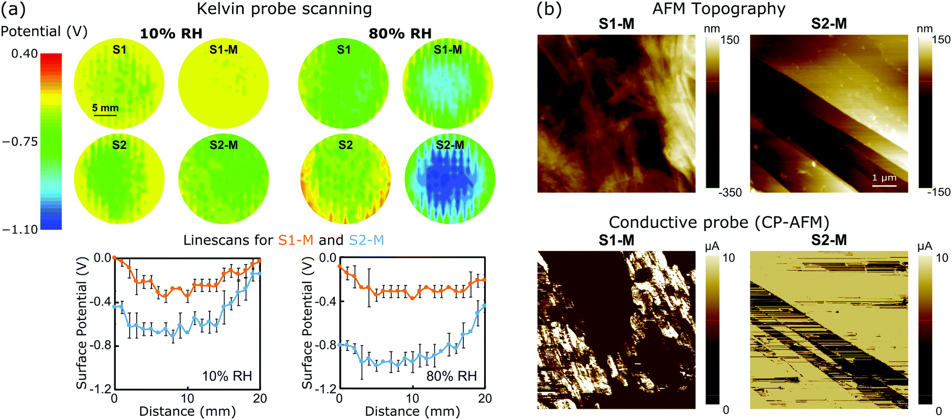 | ||
| Fig. 2 (a) (Top) Electrostatic potential maps recorded with a Kelvin probe under 10% or 80% RH for unmodified and modified ERG electrodes and (bottom) representative electrostatic potential linescans extracted at the center of S1-M and S2-M maps. (b) Conductive probe (CP-AFM): topography (top) and current (bottom) mode images of the S1-M and S2-M surfaces. See the ESI,† Sections S1.6 and S1.7, for experimental details and Fig. S5–S7 (ESI†) for additional maps. | ||
The measured open-circuit voltage (previously shown in Fig. 1) and potential difference between the electrostatic potential maps closely match, which is remarkable considering the complete independence of the two procedures. Thus, the open-circuit voltage can be understood as the algebraic sum of two half-electrode potentials, which means that the macroscopic voltage performances of the ERG-HEGs shown in Fig. 1 are the result of surface charging at the microscopic scale. Real material surfaces hardly show uniform charge distributions,1,2,14,36,37 although this is commonly assumed in simulation techniques.38–42
Thus, the output voltage of the present devices is determined by the excess of negative charge carriers, since all the measured potentials are negative, relative to the ground. This can be understood considering the asymmetric partitioning of water ions and the preference of hydroxide anions for carbon and other hydrophobic surfaces,43–47 which also accounts for the position of water in the triboelectric series.48 Consequently, the output voltage in the ERG-HEG devices is the result of different negative charging of the two electrodes, which is explained considering the adsorption of hydroxide ions from atmospheric water.1,2,13,49–51
Adsorption provokes surface saturation and a steady current output requires the continuous removal of the adsorbed ions, freeing the adsorption sites to take up new OH− ions from the environment. At this point, we suggest that the two main events accounting for the steady current production in the negative electrode are:
| OH− adsorption: OH− + S → S(OH−) | (1) |
| OH− oxidation: 2S(OH−) → 2S + H2O + ½O2 + 2e− | (2) |
Invoking the reaction of OH− ion oxidation releasing O2 and electrons may seem counter-intuitive, because this is a well-known non-spontaneous reaction in single-phase systems. However, in the present case S(OH−) is in a compartment within a multiphase system, from which the H2O + ½O2 reaction products jump to the adjacent atmosphere and electrons exit to the conductive circuit leads. The negative potential created by the adsorbed OH− ions increases the electrochemical potential of the adsorbed OH− ions, which is given by:
 | (3) |
Under −0.5 V, the (−1)FV term amounts to ca. 48 kJ mol−1, displacing the reaction (2) equilibrium towards the right side. Another way to look at this is the following: 0.5 V amounts to 40% of the standard potential (1.23 V) for water splitting, allowing this reaction to proceed to a much greater extent than under the standard cell conditions – although still far from reaching an equilibrium constant equal to or higher than 1. The ionization of surface groups followed by the pumping of H+ (ref. 20, 30–32 and 52–54) can also be part of the mechanism of continuous electrode charging, but this is not supported by the present results.
The ERG-coated Kraft sheets display very low surface resistances, typically 4 × 10⁻⁵ Ω m for thin calendered films.35 Their conductance is also evidenced in the AFM measurements shown in Fig. 2c. Topography images show that sample S1-M has a rough surface with some protrusions deriving from cellulose fibrils spread over flat areas. The calendered ERG-coated electrode surface is freer from cellulose aggregates, and displays flat carbon structures that are suitable for electronic conduction.33 This is verified by conductive probe maps (CP-AFM) (see also the ESI,† Fig. S5–S7).
The output power generation of a single m-ERG-HEG device is high enough to charge capacitors of various capacitances at a fast rate. As seen in Fig. 3a, capacitors in the nF range are instantaneously charged up to 0.45 V, which is roughly the same output voltage generated in the open-circuit condition of Fig. 1d. Also, 1.5 μF and 10 μF capacitors charge fast, while for a 100 μF capacitor the maximum voltage is reached after 250 s. Finally, a 2.2 mF capacitor has a linear charging performance with a slow charging rate (see the capacitor charging rates in the ESI,† Table S2).
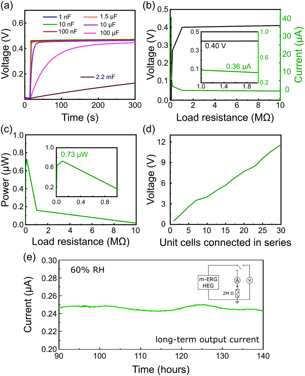 | ||
| Fig. 3 (a) Voltage curves of capacitors charged with the m-ERG-HEG device. (b) Open-circuit voltage and output current of the m-ERG-HEG with different load resistances. (c) Power delivered by the m-ERG-HEG measured for different load resistances. (d) Output voltage of m-ERG-HEG cells connected in series. All experiments were done under 60% RH. (e) Continuous recording of the current for one m-ERG-HEG cell connected to a load resistor of 2 MΩ under 60% RH. | ||
The output power of the m-ERG-HEG was tested by measuring the voltage and electric current on different resistors from 1 Ω to 10 MΩ connected to the circuit as the load (Fig. 3b). As expected, the output voltage increases with the load resistance. The power output seen in Fig. 3c shows a 0.73 μW maximum, for an optimal resistive load of 100 kΩ.
The graphite coated papers are moldable and flexible so that they can be easily packed. Thus, m-ERG-HEG units can be connected in series to increase the output voltage. Ten m-ERG-HEG devices deliver an open-circuit voltage of 4.05 V (Fig. 3d), reaching roughly 12 V for 30-unit cells connected in series. The current measured continuously through a 2 MΩ load resistor is shown in Fig. 3e, demonstrating steady energy output for almost 6 days. Harvesting energy continuously for 140 hours with an output current of 0.250 μA compares favorably with other moisture-based power generators, as shown in Table S1 (ESI†). So far, most HEGs only produce a transient current shorter than 50 s, and the more advanced ones that are capable of producing current31 have a 0.100 μA current output.
The m-ERG-HEG devices can be reduced in size, but maintaining the same output voltage with similar power performance. Fig. 4a shows 15 units that were cut, forming coin-shaped cells that are easily mounted in series and held with a plastic fastener. In this assembly, metal wires are used only for connecting to other circuit components and meters. Fig. 4b shows the voltage outputs of capacitors charged with 15 m-ERG-HEG cells. A 1 nF capacitor is instantaneously charged up to 6 V, while 10 nF to 1.5 μF capacitors reach the plateau in less than 50 s.
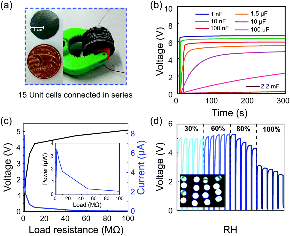 | ||
| Fig. 4 (a) Photograph of a graphite-coated Kraft paper sheet and its comparison with a coin cell (left) and 15 m-ERG-HEG cells connected in series (right) and used to (b) charge capacitors. (c) Open-circuit voltage and output current of m-ERG-HEG cells. The inset in (c) shows the peak power using this arrangement. The experiments in (b) and (c) were performed under 60% RH. (d) Charging/discharging cycles of a 1.5 μF capacitor for the cells directly connected to the capacitor under different humidities. The inset in (d) shows 16 LEDs lit up by m-ERG-HEG cells. | ||
The linear output voltage boosting reached with the m-ERG-HEG cells connected in series can be used to reach higher power outputs. Fig. 4c shows the output voltage and electric current reached when the cells are connected to different resistors, with the voltage starting from 5 V and current peaking at 7.8 μA. Also, the inset in Fig. 4c shows that the power falls sharply under increasing load, probably due to the kinetic limits imposed by mass transfer and the chemical events at the electrodes. In the present devices, the peak power is 3.55 μW through an optimal resistive load of 1 MΩ. Fig. 4d shows the capacitor charging curves and the storage of sufficient power to light up 16 ultrabright LED bulbs connected in parallel (inset Fig. 4d). Finally, a coin-shaped ERG-HEG prototype has been monitored for 12 months and persists in charging a 1.5 μF capacitor repeatedly, up to 400 mV (see the ESI,† Fig. S8), which is remarkable and highlights its stability.
Conclusions
Hygroelectric power generators built from non-metallic materials can deliver 3.55 μW peak power to an optimal resistive load of 1 MΩ, for up to 12 months. The electrodes are made out of paper coated with exfoliated and reassembled graphite (ERG), which is a new 2D macroscopic material. ERG fabrication is easily scaled up, using only inexpensive chemicals and standard industrial processes, under mild conditions. The ERG-HEG devices made from coated paper doped with common chemicals produce significant outputs under 30% RH and above, but not at 10% RH. Single ERG-HEG elements yield roughly 0.5 V and 250 nA through a 2 MΩ resistor for days. Also, they can be associated in series: a 15 ERG-HEG element series arrangement produced 5 V and 3.55 μW peak power for an optimum resistive load of 1 MΩ.The ERG-HEG can be used to charge electric devices: a 1.5 μF capacitor reaches 0.45 V in less than 5 seconds, reaching 80% of its initial voltage even after 9000 charge–discharge cycles of continuous operation. The only steady input required to keep these devices operating is the ambient humidity above 30%, which is widely found in various natural and anthropic environments. The thermodynamic argument presented to support the water-splitting reaction as the explanation for the prolonged current output by the ERG-HEG device provides guidelines for greatly improving the energy output obtained from hygroelectricity.
Conflicts of interest
There are no conflicts to declare.Acknowledgements
We would like to thank Scott Waitukaitis for insightful discussions. This work is supported by Brazilian agencies MCTIC/CNPq (465452/2014-0), FAPESP (2014/50906-9) and Coordenação de Aperfeiçoamento de Pessoal de Nível Superior – Brasil (CAPES) – Finance Code 001 through INCT/INOMAT (National Institute for Complex Functional Materials), EMU/FAPESP 2009/54066-7 and MCT/Finep/CT-Infra 02/2010. LPS thanks CAPES (88887.284776/2018-00) for a postdoctoral fellowship and Fapesp 2019/04565-9 for a research fellowship. KSM thanks Capes (88887.480279/2020-00) for a doctoral degree fellowship. This work is currently also supported by FAPESP PIPE project 2018/00834-2.References
- R. F. Gouveia and F. Galembeck, J. Am. Chem. Soc., 2009, 131, 11381–11386 CrossRef CAS.
- F. Galembeck and T. A. L. Burgo, Chemical Electrostatics, Springer, Cham, 2017 Search PubMed.
- P. Lenard, Ann. Phys., 1982, 46, 584–636 Search PubMed.
- R. Gunn, Terr. Magn. Atmos. Electr., 1935, 40, 79–106 CrossRef.
- T. Takahashi, J. Atmos. Sci., 1973, 30, 249–255 CrossRef CAS.
- S. Israelsson, J. Atmos. Sol.-Terr. Phys., 1994, 56, 1–8 CrossRef.
- C. Heinert, R. M. Sankaran and D. J. Lacks, J. Electrost., 2020, 105, 103450 CrossRef CAS.
- K. S. Moreira, D. Lermen, Y. A. S. da Campo, L. O. Ferreira and T. A. L. Burgo, Adv. Mater. Interfaces, 2020, 7, 2000884 CrossRef.
- R. Williams, J. Geophys. Res., 1989, 94, 151–167 CrossRef.
- M. Rycroft, S. Israelsson and C. Price, J. Atmos. Sol.-Terr. Phys., 2000, 62, 1563–1576 CrossRef CAS.
- J. H. Helsdon, S. Gattaleeradapan, R. D. Farley and C. Christopher Waits, J. Geophys. Res.: Atmos., 2002, 107, 4630 CrossRef.
- C. Saunders, Space Sci. Rev., 2008, 137, 335 CrossRef.
- T. R. D. Ducati, L. H. Simões and F. Galembeck, Langmuir, 2010, 26, 13763–13766 CrossRef CAS.
- R. F. Gouveia, J. S. Bernardes, T. R. D. Ducati and F. Galembeck, Anal. Chem., 2012, 84, 10191–10198 CrossRef CAS.
- A. W. Adamson and A. P. Gast, Physical Chemistry of Surfaces, Wiley, New York, 6th edn, 1997 Search PubMed.
- R. F. Gouveia, J. S. Bernardes, T. R. D. Ducati and F. Galembeck, Anal. Chem., 2012, 84, 10191–10198 CrossRef CAS.
- J. Y. Lax, C. Price and H. Saaroni, Sci. Rep., 2020, 10, 7642 CrossRef CAS.
- Y. Liang, F. Zhao, Z. Cheng, Q. Zhou, H. Shao, L. Jiang and L. Qu, Nano Energy, 2017, 32, 329–335 CrossRef CAS.
- C. Shao, J. Gao, T. Xu, B. Ji, Y. Xiao, C. Gao, Y. Zhao and L. Qu, Nano Energy, 2018, 53, 698–705 CrossRef CAS.
- X. Nie, J. Bingxue, N. Chen, Y. Liang, Q. Han and L. Qu, Nano Energy, 2018, 46, 297–304 CrossRef CAS.
- T. Xu, X. Ding, C. Shao, L. Song, T. Lin, X. Gao, J. Xue, Z. Zhang and L. Qu, Small, 2018, 14, 1–7 Search PubMed.
- Y. Han, B. Lu, C. Shao, T. Xu, Q. Liu, Y. Liang, X. Jin, J. Gao and Z. Zhang, Chem. Eng. J., 2020, 384, 123366 CrossRef CAS.
- S. S. Kwak, S. Lin, J. H. Lee, H. Ryu, T. Y. Kim, H. Zhong, H. Chen and S. W. Kim, ACS Nano, 2016, 10, 7297–7302 CrossRef CAS.
- W. Yang and C. Wang, J. Mater. Chem. C, 2016, 4, 7193–7207 RSC.
- T. Xu, X. Ding, C. Shao, L. Song, T. Lin and X. Gao, Small, 2018, 1704473 CrossRef.
- X. Li and L. Zhi, Chem. Soc. Rev., 2018, 47, 3189–3216 RSC.
- C. Yang, Y. Huang, H. Cheng, L. Jiang and L. Qu, Adv. Mater., 2019, 31, 1–7 Search PubMed.
- F. Ejehi, R. Mohammadpour, E. Asadian and P. Sasanpour, Sci. Rep., 2020, 10, 7312 CrossRef CAS.
- F. Zhao, H. Cheng, Z. Zhang, L. Jiang and L. Qu, Adv. Mater., 2015, 27, 4351–4357 CrossRef CAS.
- F. Zhao, Y. Liang, H. Cheng, L. Jiang and L. Qu, Energy Environ. Sci., 2016, 9, 912–916 RSC.
- X. Liu, H. Gao, J. E. Ward, X. Liu, B. Yin, T. Fu, J. Chen, D. R. Lovley and J. Yao, Nature, 2020, 578, 550–554 CrossRef CAS.
- H. Cheng, Y. Huang, F. Zhao, C. Yang, P. Zhang, L. Jiang, G. Shi and L. Qu, Energy Environ. Sci., 2018, 11, 2839–2845 RSC.
- L. P. Santos, D. S. da Silva, J. P. F. Bertacchi, K. S. Moreira, T. A. L. de Burgo, B. Batista, J. dos Santos, P. Alvarenga de Paula and F. Galembeck, Faraday Discuss., 2020 10.1039/C9FD00109C.
- K. Kamide and K. Okajima, US Pat., 4634470, 1983 Search PubMed.
- E. S. Ferreira, D. S. Da Silva, T. A. L. Burgo, B. C. Batista and F. Galembeck, Nanoscale, 2017, 9, 10219–10226 RSC.
- H. T. Baytekin, A. Z. Patashinski, M. Branicki, B. Baytekin, S. Soh and B. A. Grzybowski, Science, 2011, 333, 308–312 CrossRef CAS.
- T. A. L. Burgo, T. R. D. Ducati, K. R. Francisco, K. J. Clinckspoor, F. Galembeck and S. E. Galembeck, Langmuir, 2012, 28, 7407–7416 CrossRef CAS.
- X. S. Zhang, M. Di Han, R. X. Wang, F. Y. Zhu, Z. H. Li, W. Wang and H. X. Zhang, Nano Lett., 2013, 13, 1168–1172 CrossRef CAS.
- Y. Su, G. Zhu, W. Yang, J. Yang, J. Chen, Q. Jing, Z. Wu, Y. Jiang and Z. L. Wang, ACS Nano, 2014, 8, 3843–3850 CrossRef CAS.
- S. Wang, L. Lin, Y. Xie, Q. Jing, S. Niu and Z. L. Wang, Nano Lett., 2013, 13, 2226–2233 CrossRef CAS.
- R. Lei, Y. Shi, Y. Ding, J. Nie, S. Li, F. Wang, H. Zhai, X. Chen and Z. L. Wang, Energy Environ. Sci., 2020, 13, 2178–2190 RSC.
- J. K. Beattie and A. M. Djerdjev, Angew. Chem., Int. Ed., 2004, 43, 3568–3571 CrossRef CAS.
- T. W. Healy and D. W. Fuerstenau, J. Colloid Interface Sci., 2007, 309, 183–188 CrossRef CAS.
- K. N. Kudin and R. Car, J. Am. Chem. Soc., 2008, 130, 3915–3919 CrossRef CAS.
- A. Gray-Weale and J. K. Beattie, Phys. Chem. Chem. Phys., 2009, 11, 10994–11005 RSC.
- J. K. Beattie and A. Gray-Weale, Angew. Chem., Int. Ed., 2012, 51, 12941–12942 CrossRef CAS.
- N. Kallay, T. Preočanin, A. Selmani, D. Kovačević, J. Lützenkirchen, H. Nakahara and O. Shibata, J. Phys. Chem. C, 2015, 119, 997–1007 CrossRef CAS.
- T. A. L. Burgo, F. Galembeck and G. H. Pollack, J. Electrost., 2016, 80, 30–33 CrossRef.
- T. A. D. L. Burgo, C. A. Rezende, S. Bertazzo, A. Galembeck and F. Galembeck, J. Electrost., 2011, 69, 401–409 CrossRef CAS.
- L. P. Santos, T. R. D. Ducati, L. B. S. Balestrin and F. Galembeck, J. Phys. Chem. C, 2011, 115, 11226–11232 CrossRef CAS.
- T. A. L. Burgo and F. Galembeck, J. Braz. Chem. Soc., 2016, 27, 229–238 Search PubMed.
- J. Feng, M. Xiao, Z. Hui, D. Shen, Y. Tian, C. Hang, W. W. Duley and N. Y. Zhou, ACS Appl. Mater. Interfaces, 2020, 12, 24289–24297 CrossRef CAS.
- S. He, Y. Zhang, L. Qiu, L. Zhang, Y. Xie, J. Pan, P. Chen, B. Wang, X. Xu, Y. Hu, C. T. Dinh, P. De Luna, M. N. Banis, Z. Wang, T. Sham, X. Gong, B. Zhang, H. Peng and E. H. Sargent, Adv. Mater., 2018, 30, 1707635 CrossRef.
- K. Liu, P. Yang, S. Li, J. Li, T. Ding, G. Xue, Q. Chen, G. Feng and J. Zhou, Angew. Chem., Int. Ed., 2016, 55, 8003–8007 CrossRef CAS.
Footnote |
| † Electronic supplementary information (ESI) available. See DOI: 10.1039/d0ee03111a |
| This journal is © The Royal Society of Chemistry 2021 |