 Open Access Article
The journey of PDMS-based nanocomposites for EMI shielding applications: from bench to translational research
Devansh
Sharma
and
Suryasarathi
Bose
 *
*
Department of Materials Engineering, Indian Institute of Science, Bangalore 560012, India. E-mail: sbose@iisc.ac.in
First published on 31st July 2021
Abstract
The advancement in the field of electronics has allowed the miniaturization of electronic devices. Also, lightweight devices have become an integral part of our lives, especially concerning wearable gadgets. In this regard, researchers are exploring polymer nanocomposites as a potential candidate due to their inherent advantages over traditional metals for shielding electromagnetic radiation. In this journey, many polymers, ranging from thermoplastic/thermoset to intrinsically conducting polymers, were explored. Although few reviews have been published in this field, a comprehensive study on PDMS-based shielding materials did not receive much attention. However, its use in electronics has increased significantly in the recent past, especially in biomedical devices. In the last decade, researchers have explored PDMS for making composites, coating materials, and foam-like structures. In this review article, the journey of PDMS-based shielding materials has been highlighted alongside the potential applications targeted and the underlying mechanism of shielding. This comprehensive review focuses on the crucial role of functional nanoparticles that render PDMS composites conducting and make them likely candidates for EMI shielding applications. The importance of cure-kinetics and processing of PDMS-based composites is stressed here as it decides final applications such as flexible gaskets to block radio leakage to reinforced sheets for structural applications.
1. Introduction
In recent years, many researchers have focused on miniaturizing electronic devices for different applications including medical devices and electronics.1 These devices generate (electromagnetic) EM pollution in the ambient atmosphere. Thus, they can affect the working of nearby devices. Therefore, we need to protect the devices from the surrounding EM pollution. Although metals prove to be an efficient EM shields, as they usually reflect the incoming radiation to the ambient atmosphere but they are also prone to corrosion. Thus, researchers moved towards polymer-based composites for designing lightweight, easy to integrate and adapt shielding materials for EM waves.In a quest to design lightweight, easy to process, integrate, and adapt with the current process lines, researchers have explored thermosets, thermoplastics, and rubber for preparing various functional composites.2,3 They have also explored blends of two polymers as they provide the advantage offered by individual components.4 Also, one can achieve better EMI shielding by controlling the dispersion state of nanoparticles in the blend.5 Many reviews have already discussed the role of polymer nanocomposites in EMI shielding,6,7 although the use of PDMS in EMI shielding applications has not received much attention. In Fig. 1, we represent the use of various types of PDMS-based shielding materials.
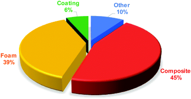 | ||
| Fig. 1 Percentage-wise representation of various forms of EM shields (based on the available literature in the last decade). | ||
PDMS, since its discovery by FS kipping in 1901, has been used in various applications such as microfluidic,8 oil separation, hydrophobicity, sensors, electromechanical devices,9–12 actuators, and sound absorbers13 because of its versatile nature. In recent years, many researchers are trying to develop flexible electronic skin using PDMS.14 This review highlights the journey of PDMS-based EMI shielding materials in the last decade. This article is divided into three sections based on the various forms of PDMS that are currently being used, such as (a) foam-like structure, (b) coatings, and (c) composites, as depicted in Fig. 1.
Under the foam category, we have considered the composite where a porous structure is used as a filler and PDMS is infiltrated such that the porosity is maintained. Secondly, PDMS is also used as a coating material for making hydrophobic surfaces and hence, finds application in making hydrophobic EMI shielding materials. Lastly, PDMS based composites for EMI shielding applications have been discussed where PDMS is used as a matrix with some filler. Also, all PDMS-based EM shielding research works are tabulated in Table 1.
| S. no. | Filler | SE/RL and SSE | Thickness (mm) | % Loading | Type | Frequency |
|---|---|---|---|---|---|---|
| 1. | MXene23 | SE= 70.5 dB | 2 mm | 6.1 wt% | Foam | X-band |
| 2. | Fe3O4 intercalated MXene and graphene24 | SE = 80 dB | 1 mm | 11.35 wt% Fe3O4@ MXene | Foam | X-band |
| SE = 77 dB | K-band | |||||
| 3. | MWCNT and GO25 | SE = 49 dB | T = 2.1 mm | GO – 100 mg | Foam | X-band |
| MWCNT – 41.3% to 91.4% | ||||||
| 4. | Iron nanoparticles and MWCNT26 | SE = 48 dB | T = 1 mm | MWCNT(0, 41.3, 64.4, 84.2, 91.2 wt%) | Foam | X-band |
| 5. | MWCNT27 | SE = 46 dB | T= 2 mm | Fe – 13 wt% | Foam | X-band |
| 6. | Graphite foam28 | SE = 36.1 dB | T = 4.3 mm | 1 wt% CNT | Foam | 8.2-18 GHz |
| 7. | Carbon nanowire (CNW)/graphene29 | SE= 36 dB | T= 1.6 mm | GF – 15.9% to 31.7% | Foam | X-band |
| 8. | rGO/ZnO (nanorods)30 | SE = 27.8 dB | T = 4.8 mm | rGO – 0.8 mg ml−1 | Foam | X-band |
| rGO/ZnO – 3.3 wt% | ||||||
| 9. | GO aerogel film/ZnO31 | SE = 43 dB | T= 1.5 mm | GO – (0.6, 0.8, 1, 1.3 mg ml−1) | Foam | X-band |
| 10. | Quartz fiber cloth/MWCNT14 | SE = 20 dB | — | rGO/ZnO – 3.3 wt% and 2 wt% MWCNT | Foam | X-band |
| 11. | Graphene foam32 | SE = 30 dB | T= 1 mm | ZnO – 21.7 wt% | Foam | 300 MHz – 1.5 GHz |
| 12. | Fe3O4 and MWCNT over cotton fabric33 | SE= 84.5 dB | T= 0.96 mm | MWCNT – 0.7–2 wt% | Coating | X-band |
| 13. | Ag coated PP fabric with PDMS layer34 | SE = 71.2 dB | T= 1.3 mm | Ag < 0.8 wt% | Coating | X-band |
| 14. | Flaky iron and PDMS35 | RL = −53.3 dB at 4.3 GHz | T = 4.3 mm | 20 wt% Fe | Composite | 2–18 GHz |
| 15. | MWCNT36 | SE ≈ −28 dB | T = 0.9 mm | Ag coating (5– 50%) | Composite | 12–18 GHz |
| 16. | Cotton fabric and MWCNT37 | SE= 41 dB | T = 1.2 mm | 20 wt% Fe | Composite | X-band |
| 17. | MWCNT/graphene38 | SE = 68 dB | T = 1 mm | 3 wt% MWCNT | Composite | X-band |
| 18. | Carbon black and rGO39 | SE = 28 dB | T= 2 mm | CTF – 15 vol% | Composite | 8–18 GHz |
| 19. | GaInSn with PDMS40 | RL = −19.3 dB at 14.8 GHz | T = 2 mm | MWCNT – 3 vol% | Composite | 2–18 GHz |
| 20. | BaTiO341 | SE = 11 dB | 200–250 μm | MWCNT – 2 wt% | Composite | X-band |
| 21. | Gd5Si4 and PDMS42 | SE∼ 69 dB | T= 1 mm | CB – 2, 5, 7, 10, 15, 17, 20 wt% | Composite | (12.4–18 GHz) |
| 22. | N-doped graphene43 | SE = 58.6 dB | T = 9.35 μm | rGO – 10, 15, 17 wt% | Composite | X-band |
| 23. | Silver nanowire/rGO44 | SE = 34.1 dB | T = 2 mm | GaInSn![[thin space (1/6-em)]](https://www.rsc.org/images/entities/char_2009.gif) : :![[thin space (1/6-em)]](https://www.rsc.org/images/entities/char_2009.gif) PDMS 3.3 PDMS 3.3![[thin space (1/6-em)]](https://www.rsc.org/images/entities/char_2009.gif) : :![[thin space (1/6-em)]](https://www.rsc.org/images/entities/char_2009.gif) 2 and 3.3 2 and 3.3![[thin space (1/6-em)]](https://www.rsc.org/images/entities/char_2009.gif) : :![[thin space (1/6-em)]](https://www.rsc.org/images/entities/char_2009.gif) 4 4 |
Composite | X-band |
| 24. | Fe3O4 over MWCNT45 | RL = 41.3 dB at 14 GHz | T= 2 mm | BaTiO3 – 15 wt% | Composite | 2–18 GHz |
| 25. | Graphene46 | SE = 54 dB | T= 2 mm | Gd5Si4 – 40 wt% | Composite | X-band |
| 26. | rGO–Fe3O4 grown over MWCNT47 | RL = −50.5 dB at 16.3 GHz | T = 1.42 mm | Fe3O4 – 4, 6, 6, 5 and 5 × 10⁻⁵ g cm−2 | Composite | 2–18 GHz |
| 27. | rGO/SWCNT48 | SE = 31 dB | T = 2 mm | AgNWs – 0.43 wt% | Composite | X-band |
| 28. | Fe3O4 embedded hollow CNF49 | RL = −25 dB | T = 7.5 mm | rGO – 0.33 wt% | Composite | 2–18 GHz |
| 29. | Ag and Fe3O410 | SE = 56.1 dB | T = 7.5 mm | Ag – 5%, 10%, 15%, 20%, 25% | Other | X-band |
| 30. | SiOC fibers50 | RC = 36 dB | T = 2.5 mm | Graphene – 3.07 wt% | Other | X-band |
| 31. | Fe3O4 coated carbon fiber51 | SE = 23 dB | T = 0.7 mm | With 0.2, 0.3, 0.4, 0.5, and 0.06 M FeCl3 | Other | X-band |
2. Mechanism of shielding in general
2.1 EM matter interaction
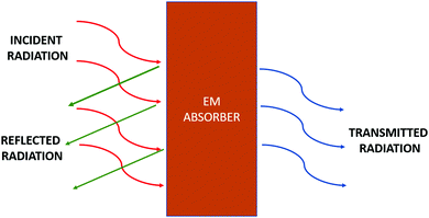
The incoming EM waves can undergo absorption, reflection, and transmission after interacting with the sample, as depicted in Fig. 2. The mode of interaction majorly depends upon the nature of the material. In general, magnetic, dielectric, or conducting material plays a vital role in EMI shielding. The incoming EM waves interact in different ways and result in the following losses.Apart from metals, the loss in other conducting materials like MWCNT and other nanowires is majorly due to conduction loss. Therefore, the incoming EM radiation tends to move the electron inside these materials, resulting in loss due to conduction. For conduction loss, the particles should form a closed percolating network for the conduction of charges under the impact of EM waves. To get insights into the impact of conductivity on EMI shielding, generally, AC conductivity response with varying frequency is studied as per Jonscher's power law given below.16
| σac = σ(0) + σ(ω) = σo + Aωn | (1) |
According to the law, the AC conductivity in a complex system like composite can be considered as the combination of resistors and capacitors. At low frequency, only resistive pathways show conductivity through tunnelling. As the frequency increases, the capacitive pathways become conductive in nature. Therefore, conductivity increases through hopping.
Thus, the law gives insights into the charge transport mechanism in a system. The value of exponent n can vary from 0 to 1 and is dependent on temperature and frequency. It represents the capacitive pathways inside the system. With increasing conductive pathways inside the system, the value of n decreases.
Nanomaterials with elongated geometry (like chains, rods, and tubular shapes) tend to form percolating networks at low concentrations and are favourable for EMI shielding applications.
2.2 Measurement of EMI shielding
The performance of EM shields to attenuate the incoming EM waves can be expressed using shielding effectiveness and reflection loss. | (2) |
SEA, SER, SEMR can be theoretically calculated using the following relations,
 | (3) |
 | (4) |
 | (5) |
But experimentally, we can calculate shielding effectiveness in terms of S-parameters as follows:
| SET (dB) = |S12|2 | (6) |
| SER (dB) = |S11|2 | (7) |
| SEA (dB) = SET − SEA | (8) |
 | (9) |
 | (10) |
3. State of the Art
3.1 PDMS based foam-like structures
Dongyi et al.22 prepared 3D graphene foam using CVD. They used nickel foam as a template over which graphene was grown. This 3D porous network was further infiltrated with PDMS under the vacuum. The prepared composite showed superior conductivity of 6100 S m−1 with only 1.2 wt% graphene. The prepared composite showed very high EMI shielding of around 40 dB for a 0.25 mm thick sample.Wu et al.23 synthesized foam-like structures using two MXene. They fabricated MXene foam using sodium alginate. Thus, the prepared conductive foam was coated with a thin layer of PDMS. Therefore, the prepared foam-like structure showed high conductivity of 2211 S cm−1 and high average shielding efficiency (SE) of 70.5 dB. After 500 compression cycles, the composite with 6.1 wt% MXene showed an SE of 48.2 dB.
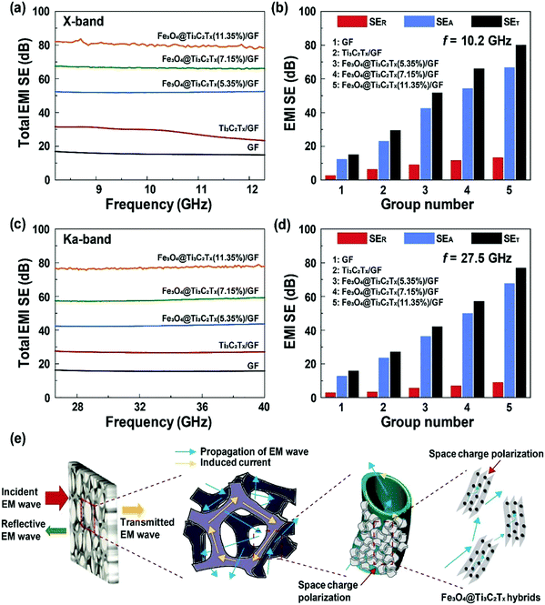
Nguyen et al.24 prepared nanocomposites using ferrite (Fe3O4) particles intercalated MXene and graphene composite for multifunctional EMI shielding, as shown in Fig. 3. They dispersed MXene in water with different concentrations (1%, 3%, and 5%), followed by the addition of Fe3O4 nanoparticles (3 wt%). Then, the formed solution was sonicated for 6 h to form a homogeneous dispersion. Graphene foam (GF) was developed using CVD on a Ni substrate followed by Fe3O4@TiC2Tx in nickel foam. After the addition of Fe3O4 particles, PDMS was introduced and cured. Finally, Ni was etched out using FeCl3 solution. They achieved a high EM shielding value for a 1 mm thick sample (SE= 80 dB in X-band and 77 dB in Ka-band) with 11.35 wt% Fe3O4@TiC2Tx particles.
Kong et al.25 synthesized high EM wave absorbing material using MWCNT and reduced graphene oxide (rGO). In the process, they first prepared a graphene oxide (GO) solution containing cobalt acetate (2 mg ml−1). The solution was freeze-dried for 24 h. Thus, obtained foam-like structure was further used to grow MWCNT using CVD. Hence, the prepared foam was coated with PDMS. The obtained foam shows an SE value reaching 49 dB for a 3.1 mm thick sample.
Yu et al.26 prepared Fe decorated porous carbon and graphene foam. They prepared a Fe nanoparticle/CNT network by carbonizing Fe(acac)3 decorated zeolitic imidazole framework-8 (ZIF-8) at 950 °C for 10 min under Ar atmosphere. The prepared composite showed shielding effectiveness (SE ∼ 48 dB) and specific shielding effectiveness as 347.8 dB cm3 g−1.
Lu et al.27 made a flexible CNT/PDMS sponge with a thickness of 2 mm. They prepared a CNT sponge using the CVD method. They infiltrated PDMS under negative pressure for 30 min followed by curing at 55 °C for 2 h. Thus, the prepared composite showed SE ∼ 46.3 dB with only 1 wt% CNT content. PDMS was infiltrated into the CNT sponge through vacuum impregnation.
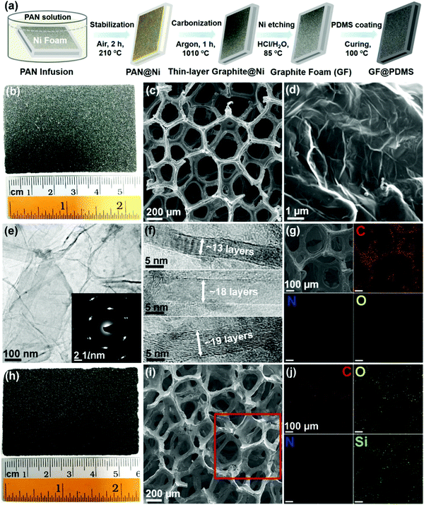
Li et al.28 obtained thin layer graphite foam (GF) with controlled density (27.2–69.2 mg cm−3) after carbonizing polyacrylonitrile foam as represented in Fig. 4. This is followed by the addition of PDMS, resulting in a porous GF@PDMS structure with varying GF concentrations from 15.9% to 31.7%. The prepared composite showed high conductivity (up to 34.3 S cm−1) and low thermal conductivity (0.062–0.076 Wm−1 K−1), and high EMI SE (up to 36.1 dB) for a 4.5 mm thick sample over the frequency range 8.2–18 GHz.
Kong et al.29 prepared covalently bonded carbon nanowire and graphene (CNWs/graphene) architecture using a bioinspired approach from polydopamine as an interface buffer fabrication of 3D macroscopic CNWs/G sponge. A thin layer of PDMS was coated by dipping foam into PDMS and curing at 150 °C for 1 h. The sponge showed excellent EMI shielding ability of (SE ∼ 36 dB) in the X-band.
Song et al.30 used three-dimensional rGO foam modified with zinc oxide (ZnO NWs) to suppress EM waves. In a typical process, they first prepared rGO foam using the freeze-drying method, followed by the synthesis of ZnO nanowires using seed-mediated growth. They infiltrated PDMS using a vacuum. The porous EMI shield showed minimum RC (RCmin = −31.1 dB) for ZnO NWs/RGO foam/PDMS with 0.8 mg ml−1 RGO at 9.2 GHz for a 5 mm thick sample.
Han et al.31 synthesized composite film using rGO and zinc by dispersing zinc in an acidic solution of GO. The composite film was dialyzed for 12 h to remove acidic impurities. The obtained gel was freeze-dried for 36 h to make the foam-like structure. PDMS was infiltrated, and the sample was cured at 80 °C for 4 h. For preparing a multilayer stack, several such layers were used in combination. The composite showed SE ∼ 23 dB. Also, they claimed that the composite film acts as an absorber and reflector in X-band. For the multilayer structure, they achieved SE ∼ 47 dB to 53 dB.
Chen et al.14 used quartz fiber cloth (QFC) reinforced MWCNTs-carbon aerogel (QMCA) by chemical route. The prepared gel was freeze-dried to form the final porous structure. The PDMS based composite was made through vacuum infiltration followed by curing at 90 °C for 30 min. The prepared composite showed EM shielding of SE ∼ 20 dB.
Chen et al.32 prepared lightweight graphene foam composites with a density of 0.06 g cm−3. In a typical process, they have grown graphene over Ni substrate; after that thin layer of PDMS was coated over the foam. After PDMS coating, Ni was etched out by dipping into HCl solution for 24 h. The prepared sample shows SE∼30 dB and specific shielding effectiveness of 500 dB cm3 g−1 in the frequency range (300 MHz–1.5 GHz). The foam composite showed excellent SE even after bending for 10000 cycles.
3.2 PDMS based coating materials
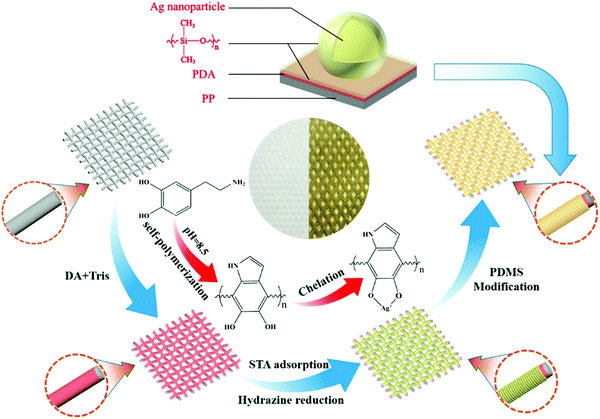
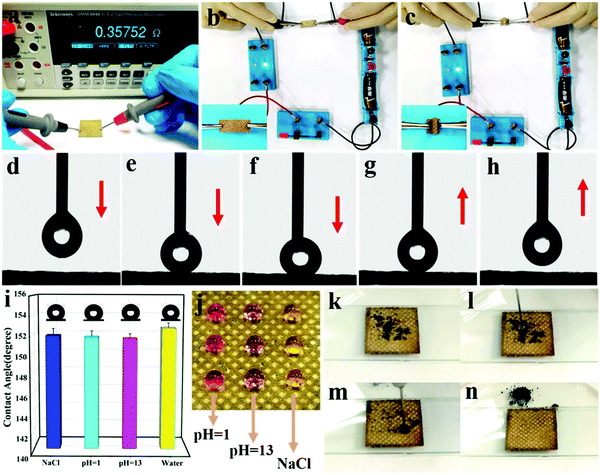
Wang et al.33 prepared layer-by-layer assembly using Fe3O4 and MWCNT over the cotton fabric to shield the EM waves. After the deposition of nanoparticles, the fabric was coated with PDMS. The robust EM shielding material showed shielding effectiveness of ≈ 84.5 dB in X-band with 0.96 mm thickness and good thermal conductivity.Luo et al.34 developed a self-cleaning composite for EMI shielding application by coating PDMS over PP fabric, as depicted in Fig. 5. They prepared the composite in three steps; firstly, they prepared PDA coating over the PP surface followed by chemically reducing Ag over the PP fabric. The obtained fabric was coated with a PDMS layer to provide hydrophobicity. The prepared composite showed high contact angle of ∼152.3°. The coated fabric shows high conductivity of 81.2 S cm−1 and SE ∼ 71.2 dB (refer Fig. 6).
3.3 PDMS based nanocomposites
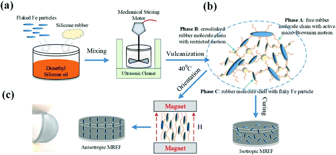
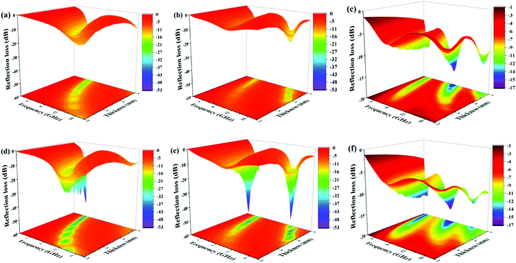
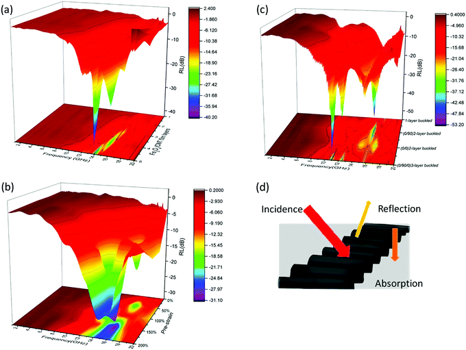
Zheng et al.35 used flaky iron (F–Fe) (20 wt% and 28 wt%) as a filler to prepare magnetorheological film by mixing F–Fe in dimethyl silicone oil as shown in Fig. 7, followed by the addition of silicone rubber (SR). This solution was thoroughly mixed using a mechanical mixer. After this, the solution was vulcanized at 40 °C for 12 h. For preparing the aligned sample, the sample was cured under a 200 mT magnetic field. They compared the EM shielding performance of the prepared sample with a wax alternative. They got a minimum reflection loss (RL) value of −53.3 dB at 4.3 GHz for a 4.3 mm sample (refer to Fig. 8).Nallabothula et al.36 used two different processes, i.e., spin coating and compression moulding for dispersing MWCNT in PDMS matrix and studied the effect of the processing technique on the state of dispersion and EMI shielding performance of the prepared composite. They further formed a multilayer stack by dispersing Fe3O4 particles and MWCNT with the optimized process. They found that compression moulding results in proper dispersion of MWCNT compared to spin coating. For the multilayer stack, they achieved SE ≈ −28 dB for a 0.9 mm thick sample.
Li et al.37 used cotton fibres (CTF) in addition to MWCNT to construct multiple interfaces in PDMS-based composite. They dispersed MWCNT in PDMS by ultrasonication in dichloromethane solvent, followed by degassing and post-curing at 80 °C for 2 h. They found that the EM shielding effectiveness (SE) for the sample with 2 vol% and 3 vol% MWCNT increases from ∼16 dB to ∼30 dB and ∼20 dB to ∼41 dB with the addition of 15 wt% CTF for 1.2 mm thick sample.
Zhu et al.38 prepared a composite using cake-like flexible MWCNT/graphene and PDMS. In a typical process, they oxidized MWCNT (OCNT) using Hummers' method. Thus, the obtained OCNTs wet cake was freeze-dried and re-grinded. The OCNT/graphene (G) were dispersed together and filtered using a PTFE membrane, therefore, giving a wet cake-like structure followed by drying at 60 °C for 6 h and calcining at 1000 °C for 2 h in Ar atmosphere. Finally, the system was infiltrated with PDMS using a vacuum. They found that the composite with thermally treated graphene and OCNT shows SE ≈ 68 dB (X-band) for a 1.2 mm thick sample.
Anooja et al.39 made composites using carbon black (CB) and reduced graphene oxide (rGO) in PDMS. They mixed CB (2 wt%, 5 wt%, 10 wt%, and 17 wt%) in rGO (5 wt% and 15 wt%) solution and sonicated for 30 min. In the above-sonicated solution, PDMS was added and dried overnight. The as-obtained powder was compressed at 200 °C for 20 min. The prepared composite with rGO 15 wt% and CB 17 wt% showed SE ∼ 28 dB in the 8–18 GHz range. The composite retained its EM shielding ability even after 1000 bending cycles.
Ou et al.40 developed PDMS-based composites using Galinstan (GaInSn) liquid metal. Firstly, they dispersed GaInSn into PDMS by physical mixing. They prepared two different samples with GaInSn![[thin space (1/6-em)]](https://www.rsc.org/images/entities/char_2009.gif) :
:![[thin space (1/6-em)]](https://www.rsc.org/images/entities/char_2009.gif) PDMS ratios as 1
PDMS ratios as 1![[thin space (1/6-em)]](https://www.rsc.org/images/entities/char_2009.gif) :
:![[thin space (1/6-em)]](https://www.rsc.org/images/entities/char_2009.gif) 4 and 1
4 and 1![[thin space (1/6-em)]](https://www.rsc.org/images/entities/char_2009.gif) :
:![[thin space (1/6-em)]](https://www.rsc.org/images/entities/char_2009.gif) 8. The minimum reflection loss (RL) achieved using GaInSn/PDMS composite is −19.3 dB at 14.8 GHz at a thickness of 2 mm. They also observed a shift in the RL peak from 14.8 GHz to 9.7 GHz after 30% elongation.
8. The minimum reflection loss (RL) achieved using GaInSn/PDMS composite is −19.3 dB at 14.8 GHz at a thickness of 2 mm. They also observed a shift in the RL peak from 14.8 GHz to 9.7 GHz after 30% elongation.
Lee et al.41 prepared a plaid pattern over composite made from bio-PDMS and BaTiO3 (MBPBT). They made the composite using MWCNT and MBPBT. Another solution made from (AgNWs) and Fe3O4 nanoparticles was a deposit on MBPBT. The two composite films (with MWCNT and Ag NWs) were arranged in two different configurations (parallel and cross configurations). Thus, the prepared composite showed a high EM shielding ability of 11 dB in cross configuration with 15 wt% BaTiO3.
Bora et al.42 prepared composites using soft magnetic Gd5Si4 nanoparticles and PDMS. Gd5Si4 nanoparticles were made from the bulk composite using an arc discharge method followed by ball milling for 2 h. Thus obtained (40 wt%) nanoparticles were dispersed in PDMS and cured in a vacuum oven at 60 °C for 6 h. They tested the EM shielding ability of the composite in the Ka-band (12.4–18 GHz). The prepared composite showed SE ∼ 69 dB for a 6 mm thick sample.
Lin et al.43 fabricated ultrathin nitrogen-doped graphene film by vacuum filtration followed by compression moulding. Thus obtained graphene films were modified using ethylenediamine (EDA). The compressed sheets were spin-coated over the PDMS substrate. For preparing wavy sheet-like structures, the GO sheets were transferred to the pre-molded PDMS substrate. The prepared sample with 6.6 μm thickness showed shielding effectiveness of 58.6 dB. They observed that the modified GO sheets showed better shielding effectiveness.
Li et al.44 prepared highly conductive and robust 3D graphene/silver nanowires bi-continuous skeletons for EM shielding. They used the Ag NWs and rGO bi-continuous network (3D bi-continuous network). With low filler concentration, 0.76 wt% possessed high conductivities of 10.6 S cm−1. The sample showed SE ∼ 34.1 dB; hence, the prepared sample shows excellent thermal conductivity and high compression strength.
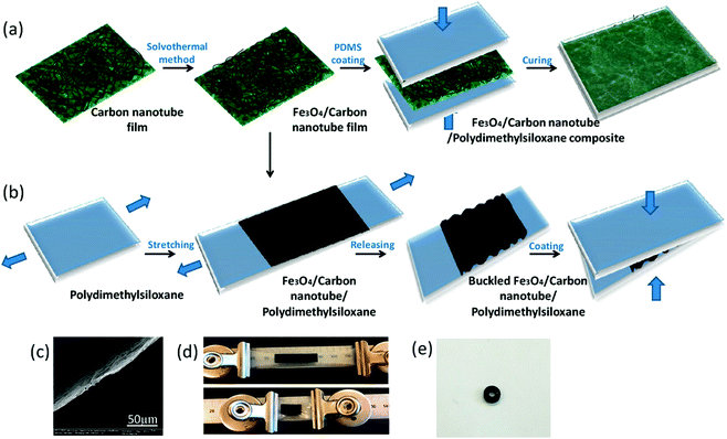
Shao et al.45 prepared stretchable nanocomposites using Fe3O4/CNT/PDMS composite film using in situ grown Fe3O4 over CNT film using the solvothermal method. The obtained Fe3O4 over CNT film was used to prepare the PDMS composite in planar and wave-like structures (Fig. 9). Firstly, for fabricating the planar composite, the Fe3O4/CNT film was coated over the PDMS substrate, followed by a thin layer coating of PDMS. They also prepared wrinkled films by coating over the pre-stretched film and releasing the stress. They found that with an increasing number of layers, the shielding ability of the composite increases. For 5 layers, they achieved minimum RL ∼ −41.3 dB at 14 GHz with a bandwidth of 10 dB (refer to Fig. 10).
Xu et al.46 prepared PDMS-based nanocomposites by direct infiltration into the interconnected rGO network. With the addition of graphene, the mechanical property of the composite increased. For a composite with 3.07 wt%, they achieved high electrical conductivity (∼ 103 S cm−1), and the composite showed SE of 54 dB in X-band for a 2 mm thick sample.
Li et al.47 used CNT film fabricated utilizing a CVD process followed by a solvothermal process to prepare CNT–Fe3O4 composites with different concentrations of Fe3O4. Reduced graphene oxide (rGO) was deposited on the sample using the electrophoretic technique. The prepared rGO–CNT–Fe3O4 composite film was coated with a thin layer of PDMS and cured for 1 h at 100 °C. The composite film showed minimum RL ∼ −50.5 dB at 16.3 GHz for four-layer (t =1.42 mm) composite with the bandwidth of 5.7 GHz with (RL > 10 dB).
Zhao et al.48 prepared PDMS/rGO/SWCNT (single-walled carbon nanotube) composite through backfilling the rGO/SWCNT aerogel. The composite showed excellent electrical conductivity of 1.2 S cm−1 and EM shielding effectiveness of 31 dB over X-band with low filler content (0.28 wt%) for a 2 mm thick sample.
Mordina et al.49 used Fe3O4 embedded hollow carbon nanofiber (CNF) with PDMS to prepare an efficient EM shield. In a typical process, they used co-electrospinning to prepare nanofiber from polyacrylonitrile/FeCl3 and poly(methyl methacrylate) followed by carbonization at a higher temperature. The obtained nanofibers were used to fabricate a composite with PDMS. The composite with 25 wt% carbon nanofiber (consisting of 5 wt% Fe3O4) gives RL= −25 dB with an absorption bandwidth of 4.33 GHz for a 7.5 mm thick sample.
3.4 Others
Luo et al.10 prepared superhydrophobic and multi-responsive polypropylene fabric for EM shielding by depositing Ag nanoparticles over the ozone-treated fabric followed by spray coating with a mixture of Fe3O4 and PDMS. The obtained fabric showed excellent conductivity (up to 108.8 S cm−1) and EM shielding effectiveness (SE ∼ 56.1 dB) in X-band. The material showed excellent stability against sonication, abrasion, and bending tests.Duan et al.50 prepared novel SiOC ceramic by pyrolysis of hyperbranched ferrocene-containing polysiloxane (HBPSO-VF), obtained as a product of reacting polysiloxane (PSO) with 1,1′- bis(dimethylvinylsilyl)ferrocene (VF) at 160 °C for 2 h. The obtained product was ball milled for 2 h and pellets were formed by cold press. The obtained pellets were pyrolyzed at 900 °C in the Ar atmosphere. The obtained ceramic was annealed at a different temperature from 1000–1450 °C in the Ar atmosphere. The composite with 1 wt% Fe and thickness of 2.5 mm calcined at 1100 °C showed RC ∼ 36 dB.
Bayat et al.51 studied the effect of PDMS coating on the EMI shielding ability of the Fe3O4 coated carbon fiber. They used electrospinning to fabricate polyacrylonitrile (PAN) based fiber filled with Fe3O4 nanoparticles in a typical process. The obtained fibers were carbonized at 900 °C. Thus obtained samples were coated with PDMS. They found no significant effect of PDMS coating on the EM shielding ability of the composite (SE ∼ 23 dB) for t = 0.25 mm.
4. Perspective
The journey of PDMS-based composites from bench to translational research for EMI shielding applications is reviewed here in detail. In the last decade, various forms of PDMS-based nanocomposites for the targeted applications have been designed to cater to different applications like flexible gaskets, reinforced sheets, encapsulating critical biomedical devices, contact lenses, etc. In addition to making various components, PDMS-based coatings over porous structures obtained by carbonization of various foams resulting in foam-like structures have also been attempted. Since, PDMS is transparent to EM waves, various functional nanoparticles have been added to render the composites with key attributes, such as conducting, magnetic, and/or dielectric properties. However, the presence of sulphur inhibits the catalytic activity of Pt-based catalysts; therefore, in most cases, researchers have used tin-based catalysts for crosslinking, which is key to realizing the exceptional properties that PDMS has to offer.52 This further leads to preparing composites using a hydrosilylation crosslinking mechanism, which is more environmentally friendly. Recently, researchers have also explored click chemistry to enhance the crosslinking in PDMS.From the current state-of-the-art literature, it is well understood that PDMS-based foams are the most popular choice for designing lightweight EMI shielding materials. Among the various particle systems, 2D nanomaterials (like MoS2, WS2, and others) need to be explored as the huge specific surface area of these 2D nanomaterials can help shield through multiple internal reflections/scattering. In addition, nanoporous materials like metal–organic frameworks (MOF) and covalent organic frameworks (COF), when blended with PDMS, offer a range of functional particles that can be further explored for EMI shielding materials. Due to their high thermal stability, these polymer composites can be used to shield electronic devices operating at high temperatures and, in addition, can also dissipate heat, thereby protecting the precise electronics. More research should be focused on enhancing the shelf life of these composites by incorporating functional particles that can block both UV as well as EMI.
The use of PDMS based nanocomposites is more favourable as PDMS is biocompatible and hence, less harmful to the environment. Such nanocomposite nanocomposites can find their potential use in the healthcare industry. Also, owing to their high thermal stability, these nanocomposites can find their application in devices operating at higher temperatures. Also, these composites or coatings are mostly in demand in moisture sensitive equipment as PDMS shows very high hydrophobicity.
This review article highlights the journey of PDMS-based composites designed for EMI shielding applications. Various case studies have been presented to help guide the researchers working in this area from both industry and academia. Given the surge in the operating frequencies (higher GHz), more research should focus on PDMS based composites with hybrid and/or core–shell structures, multi-layered architectures, and both rigid/soft foam-like structures.
Conflicts of interest
There are no conflicts to declare.References
- J. Pomposo, J. Rodrıguez and H. Grande, Polypyrrole-based conducting hot melt adhesives for EMI shielding applications, Synth. Met., 1999, 104(2), 107–111 CrossRef CAS.
- R. Rohini and S. Bose, Electrodeposited carbon fiber and epoxy based sandwich architectures suppress electromagnetic radiation by absorption, Composites, Part B, 2019, 161, 578–585 CrossRef CAS.
- M. Sharma, M. P. Singh, C. Srivastava, G. Madras and S. Bose, Poly(vinylidene fluoride)-Based Flexible and Lightweight Materials for Attenuating Microwave Radiations, ACS Appl. Mater. Interfaces, 2014, 6(23), 21151–21160 CrossRef CAS.
- S. P. Pawar, D. A. Marathe, K. Pattabhi and S. Bose, Electromagnetic interference shielding through MWNT grafted Fe3O4 nanoparticles in PC/SAN blends, J. Mater. Chem. A, 2015, 3(2), 656–669 RSC.
- R. Rohini and S. Bose, Electromagnetic Interference Shielding Materials Derived from Gelation of Multiwall Carbon Nanotubes in Polystyrene/Poly(methyl methacrylate) Blends, ACS Appl. Mater. Interfaces, 2014, 6(14), 11302–11310 CrossRef CAS.
- S. P. Pawar, S. Biswas, G. P. Kar and S. Bose, High frequency millimetre wave absorbers derived from polymeric nanocomposites, Polymer, 2016, 84, 398–419 CrossRef CAS.
- M. H. Al-Saleh, W. H. Saadeh and U. Sundararaj, EMI shielding effectiveness of carbon based nanostructured polymeric materials: A comparative study, Carbon, 2013, 60, 146–156 CrossRef CAS.
- C. L. Bliss, J. N. McMullin and C. J. Backhouse, Integrated wavelength-selective optical waveguides for microfluidic-based laser-induced fluorescence detection, Lab Chip, 2008, 8(1), 143–151 RSC.
- C. Cao, M. Ge, J. Huang, S. Li, S. Deng, S. Zhang, Z. Chen, K. Zhang, S. S. Al-Deyab and Y. Lai, Robust fluorine-free superhydrophobic PDMS–ormosil@fabrics for highly effective self-cleaning and efficient oil–water separation, J. Mater. Chem. A, 2016, 4(31), 12179–12187 RSC.
- J. Luo, L. Huo, L. Wang, X. Huang, J. Li, Z. Guo, Q. Gao, M. Hu, H. Xue and J. Gao, Superhydrophobic and multi-responsive fabric composite with excellent electro-photo-thermal effect and electromagnetic interference shielding performance, Chem. Eng. J., 2019, 123537 Search PubMed.
- Y. He, Y. Ming, W. Li, Y. Li, M. Wu, J. Song, X. Li and H. Liu, Highly stable and flexible pressure sensors with modified multi-walled carbon nanotube/polymer composites for human monitoring, Sensors, 2018, 18(5), 1338 CrossRef PubMed.
- D. He, Y. Xie, X. Wang and Z. Zhang, Significantly Enhanced Electromechanical Performance of PDMS Crosslinked PVDF Hybrids, Polymers, 2018, 10(7), 714 CrossRef PubMed.
- Y. Wu, X. Sun, W. Wu, X. Liu, X. Lin, X. Shen, Z. Wang, R. K. Y. Li, Z. Yang, K.-T. Lau and J.-K. Kim, Graphene foam/carbon nanotube/poly(dimethyl siloxane) composites as excellent sound absorber, Composites, Part A, 2017, 102, 391–399 CrossRef CAS.
- M. Chen, L. Zhang, S. Duan, S. Jing, H. Jiang, M. Luo and C. Li, Highly conductive and flexible polymer composites with improved mechanical and electromagnetic interference shielding performances, Nanoscale, 2014, 6(7), 3796–3803 RSC.
- R. R. Mishra and A. K. Sharma, Microwave–material interaction phenomena: Heating mechanisms, challenges and opportunities in material processing, Composites, Part A, 2016, 81, 78–97 CrossRef CAS.
- K. L. Ngai, A. K. Jonscher and C. T. White, On the origin of the universal dielectric response in condensed matter, Nature, 1979, 277(5693), 185–189 CrossRef CAS.
- H. Zhang and A. K. Datta, Microwave Power Absorption in Single - and Multiple - Item Foods, Food Bioprod. Process., 2003, 81(3), 257–265 CrossRef.
- M. Sparks, R. Loudon and C. Kittel, Ferromagnetic relaxation. I. Theory of the relaxation of the uniform precession and the degenerate spectrum in insulators at low temperatures, Phys. Rev., 1961, 122(3), 791 CrossRef CAS.
- D. M. Pozar, Microwave engineering, John Wiley & Sons, 2009 Search PubMed.
- A. J. Moulson and J. M. Herbert, Electroceramics: materials, properties, applications, John Wiley & Sons, 2003 Search PubMed.
- J. L. Snoek, Dispersion and absorption in magnetic ferrites at frequencies above one Mc/s, Physica, 1948, 14(4), 207–217 CrossRef CAS.
- D. Ao, Y. Tang, X. Xu, X. Xiang, J. Yu, S. Li and X. Zu, Highly Conductive PDMS Composite Mechanically Enhanced with 3D-Graphene Network for High-Performance EMI Shielding Application, Nanomaterials, 2020, 10(4), 768 CrossRef CAS PubMed.
- X. Wu, B. Han, H.-B. Zhang, X. Xie, T. Tu, Y. Zhang, Y. Dai, R. Yang and Z.-Z. Yu, Compressible, durable and conductive polydimethylsiloxane-coated MXene foams for high-performance electromagnetic interference shielding, Chem. Eng. J., 2020, 381, 122622 CrossRef CAS.
- V.-T. Nguyen, B. K. Min, Y. Yi, S. J. Kim and C.-G. Choi, MXene(Ti3C2TX)/graphene/PDMS composites for multifunctional broadband electromagnetic interference shielding skins, Chem. Eng. J., 2020, 393, 124608 CrossRef CAS.
- L. Kong, X. Yin, H. Xu, X. Yuan, T. Wang, Z. Xu, J. Huang, R. Yang and H. Fan, Powerful absorbing and lightweight electromagnetic shielding CNTs/RGO composite, Carbon, 2019, 145, 61–66 CrossRef CAS.
- C. Yu, S. Zhu, C. Xing, X. Pan, X. Zuo, J. Liu, M. Chen, L. Liu, G. Tao and Q. Li, Fe nanoparticles and CNTs co-decorated porous carbon/graphene foam composite for excellent electromagnetic interference shielding performance, J. Alloys Compd., 2020, 820, 153108 CrossRef CAS.
- D. Lu, Z. Mo, B. Liang, L. Yang, Z. He, H. Zhu, Z. Tang and X. Gui, Flexible, lightweight carbon nanotube sponges and composites for high-performance electromagnetic interference shielding, Carbon, 2018, 133, 457–463 CrossRef CAS.
- H. Li, L. Jing, Z. L. Ngoh, R. Y. Tay, J. Lin, H. Wang, S. H. Tsang and E. H. T. Teo, Engineering of High-Density Thin-Layer Graphite Foam-Based Composite Architectures with Superior Compressibility and Excellent Electromagnetic Interference Shielding Performance, ACS Appl. Mater. Interfaces, 2018, 10(48), 41707–41716 CrossRef CAS PubMed.
- L. Kong, X. Yin, M. Han, X. Yuan, Z. Hou, F. Ye, L. Zhang, L. Cheng, Z. Xu and J. Huang, Macroscopic bioinspired graphene sponge modified with in-situ grown carbon nanowires and its electromagnetic properties, Carbon, 2017, 111, 94–102 CrossRef CAS.
- C. Song, X. Yin, M. Han, X. Li, Z. Hou, L. Zhang and L. Cheng, Three-dimensional reduced graphene oxide foam modified with ZnO nanowires for enhanced microwave absorption properties, Carbon, 2017, 116, 50–58 CrossRef CAS.
- D. Han, Y.-H. Zhao, S.-L. Bai and W. C. Ping, High shielding effectiveness of multilayer graphene oxide aerogel film/polymer composites, RSC Adv., 2016, 6(95), 92168–92174 RSC.
- Z. Chen, C. Xu, C. Ma, W. Ren and H.-M. Cheng, Lightweight and Flexible Graphene Foam Composites for High-Performance Electromagnetic Interference Shielding, Adv. Mater., 2013, 25(9), 1296–1300 CrossRef CAS PubMed.
- Y. Wang, W. Wang, Q. Qi, N. Xu and D. Yu, Layer-by-layer assembly of PDMS-coated nickel ferrite/multiwalled carbon nanotubes/cotton fabrics for robust and durable electromagnetic interference shielding, Cellulose, 2020, 27(5), 2829–2845 CrossRef CAS.
- J. Luo, L. Wang, X. Huang, B. Li, Z. Guo, X. Song, L. Lin, L.-C. Tang, H. Xue and J. Gao, Mechanically Durable, Highly Conductive, and Anticorrosive Composite Fabrics with Excellent Self-Cleaning Performance for High-Efficiency Electromagnetic Interference Shielding, ACS Appl. Mater. Interfaces, 2019, 11(11), 10883–10894 CrossRef CAS.
- J. Zheng, X. He, Y. Li, B. Zhao, F. Ye, C. Gao, M. Li and X. Li, E, S., Viscoelastic and Magnetically Aligned Flaky Fe-Based Magnetorheological Elastomer Film for Wide-Bandwidth Electromagnetic Wave Absorption, Ind. Eng. Chem. Res., 2020, 59(8), 3425–3437 CrossRef CAS.
- H. Nallabothula, Y. Bhattacharjee, L. Samantara and S. Bose, Processing-Mediated Different States of Dispersion of Multiwalled Carbon Nanotubes in PDMS Nanocomposites Influence EMI Shielding Performance, ACS Omega, 2019, 4(1), 1781–1790 CrossRef CAS.
- J. Li, Y.-J. Tan, Y.-F. Chen, H. Wu, S. Guo and M. Wang, Constructing multiple interfaces in polydimethylsiloxane/multi-walled carbon nanotubes nanocomposites by the incorporation of cotton fibers for high-performance electromagnetic interference shielding and mechanical enhancement, Appl. Surf. Sci., 2019, 466, 657–665 CrossRef CAS.
- S. Zhu, C. Xing, F. Wu, X. Zuo, Y. Zhang, C. Yu, M. Chen, W. Li, Q. Li and L. Liu, Cake-like flexible carbon nanotubes/graphene composite prepared via a facile method for high-performance electromagnetic interference shielding, Carbon, 2019, 145, 259–265 CrossRef CAS.
- J. B. Anooja, K. S. Dijith, K. P. Surendran and G. Subodh, A simple strategy for flexible electromagnetic interference shielding: Hybrid rGO@CB-Reinforced polydimethylsiloxane, J. Alloys Compd., 2019, 807, 151678 CrossRef.
- M. Ou, H. Liu, X. Chen, S. Chu and G. Chu, Tunable electromagnetic wave-absorbing capability achieved in liquid-metal-based nanocomposite, Appl. Phys. Express, 2019, 12(4), 045005 CrossRef CAS.
- D. W. Lee, J. Park, B. J. Kim, H. Kim, C. Choi, R. H. Baughman, S. J. Kim and Y. T. Kim, Enhancement of electromagnetic interference shielding effectiveness with alignment of spinnable multiwalled carbon nanotubes, Carbon, 2019, 142, 528–534 CrossRef CAS.
- P. J. Bora, S. M. Harstad, S. Gupta, V. K. Pecharsky, K. J. Vinoy, P. C. Ramamurthy and R. L. Hadimani, Gadolinium silicide (Gd5Si4) nanoparticles for tuneable broad band microwave absorption, Mater. Res. Express, 2019, 6(5), 055053 CrossRef CAS.
- S. Lin, S. Ju, G. Shi, J. Zhang, Y. He and D. Jiang, Ultrathin nitrogen-doping graphene films for flexible and stretchable EMI shielding materials, J. Mater. Sci., 2019, 54(9), 7165–7179 CrossRef CAS.
- Y. Li, C. Li, S. Zhao, J. Cui, G. Zhang, A. Gao and Y. Yan, Facile fabrication of highly conductive and robust three-dimensional graphene/silver nanowires bicontinuous skeletons for electromagnetic interference shielding silicone rubber nanocomposites, Composites, Part A, 2019, 119, 101–110 CrossRef CAS.
- Y. Shao, J. Li, W. Lu, J. Q. Xiao, Y. Qiu and T.-W. Chou, Microbuckling-Enhanced Electromagnetic-Wave-Absorbing Capability of a Stretchable Fe3O4/Carbon Nanotube/Poly(dimethylsiloxane) Composite Film, ACS Appl. Nano Mater., 2018, 1(5), 2227–2236 CrossRef CAS.
- F. Xu, R. Chen, Z. Lin, Y. Qin, Y. Yuan, Y. Li, X. Zhao, M. Yang, X. Sun, S. Wang, Q. Peng, Y. Li and X. He, Superflexible Interconnected Graphene Network Nanocomposites for High-Performance Electromagnetic Interference Shielding, ACS Omega, 2018, 3(3), 3599–3607 CrossRef CAS PubMed.
- J. Li, Y. Xie, W. Lu and T.-W. Chou, Flexible electromagnetic wave absorbing composite based on 3D rGO-CNT-Fe3O4 ternary films, Carbon, 2018, 129, 76–84 CrossRef CAS.
- S. Zhao, Y. Yan, A. Gao, S. Zhao, J. Cui and G. Zhang, Flexible Polydimethylsilane Nanocomposites Enhanced with a Three-Dimensional Graphene/Carbon Nanotube Bicontinuous Framework for High-Performance Electromagnetic Interference Shielding, ACS Appl. Mater. Interfaces, 2018, 10(31), 26723–26732 CrossRef CAS.
- B. Mordina, R. Kumar, R. K. Tiwari, D. K. Setua and A. Sharma, Fe3O4 Nanoparticles Embedded Hollow Mesoporous Carbon Nanofibers and Polydimethylsiloxane-Based Nanocomposites as Efficient Microwave Absorber, J. Phys. Chem. C, 2017, 121(14), 7810–7820 CrossRef.
- W. Duan, X. Yin, C. Luo, J. Kong, F. Ye and H. Pan, Microwave-absorption properties of SiOC ceramics derived from novel hyperbranched ferrocene-containing polysiloxane, J. Eur. Ceram. Soc., 2017, 37(5), 2021–2030 CrossRef CAS.
- M. Bayat, H. Yang, F. K. Ko, D. Michelson and A. Mei, Electromagnetic interference shielding effectiveness of hybrid multifunctional Fe3O4/carbon nanofiber composite, Polymer, 2014, 55(3), 936–943 CrossRef CAS.
- V. Srinivas, Y. Nakajima, W. Ando, K. Sato and S. J. C. S. Shimada, (Salicylaldiminato)Ni(II)-catalysts for hydrosilylation of olefins, Catal. Sci. Technol., 2015, 5(4), 2081–2084 RSC.
| This journal is © The Royal Society of Chemistry 2021 |

