 Open Access Article
Creative Commons Attribution 3.0 Unported Licence
Preparation of flower-like iron phosphate materials as a novel anode for dual-ion batteries
Wenbiao
Yao
a,
Xueyin
Che
a,
Jiahui
Li
a,
LiLi
Zhao
a,
Hua
Yang
b,
Yongdong
Wang
a,
Chao
Li
 *a and
Wenbo
Liao
a
aCollege of Chemical Engineering and Energy Technology, Dongguan University of Technology, Dongguan 523808, China. E-mail: lichao@dgut.edu.cn; dglichao520@126.com
bDongguan Neutron Science Center, No. 1 Zhongziyuan Road, Dalang, Dongguan 523803, China
First published on 7th September 2021
Abstract
Dual-ion batteries (DIBs) have exceptional advantages over other electrochemical energy storage devices. In particular, the application of graphite cathodes exhibits superior properties in terms of cost and safety. However, these batteries still suffer from decomposition of the electrolyte under a high voltage for the traditional anode electrode. At the same time, the formation the solid electrolyte interphase (SEI) of the anode also results in a high irreversibility. In this study, a novel type of anode material, FePO4, is explored for possible applications in DIBs. The low voltage range of FePO4 is controlled by partial lithiation to improve the cycling stability. The flower-like structure can enable fast transportation of the electrons and ions in an ultra-thick electrode. Furthermore, the electrochemical performance was studied in great detail under different loading masses in full batteries. The results of the studies confirm that FePO4 could yield stable cycling of DIBs, showing obvious application advantages with low costs and without resource constraints for medium and long-term development opportunities.
1. Introduction
With large-scale applications in the field of electric vehicles, the blooming lithium-ion batteries (LIBs) industry has been developed to meet the continuous requirements for mass production. Currently, transition metals such as nickel, cobalt and manganese are important components in the cathodes of LIBs. However, these metal resources, which are employed for use in cathodes, are constantly depleting, severely affecting the future industrial development of LIBs.1–5 On the other hand, instability of the cathode matrix structures could induce crystalline failure, for example overcharging, over-heating, manufacturing problems and various other issues.6–10 This, in turn, could lead to thermal runaway and security issues.11,12 Hence, resource limitation and potential safety concerns are the main bottlenecks to the widespread application of LIBs in the electric vehicle field.Faced with the large-scale application of LIBs, alternative dual-ion batteries (DIBs) have been increasingly explored in recent years. DIBs are promising energy-storage systems owing to their special storage mechanisms and material characteristics.13–18 Unlike the “rocking-chair structure” of LIBs, anions such as PF6− in the electrolyte are inserted into the layered-graphite cathodes of DIBs and the lithium ions migrate towards the anode electrode during charging.19,20 These ions will then return to the electrolyte after discharge owing to the transfer of anions and cations from the electrolyte. At voltages of 5.4 or 5.5 V (vs. lithium reference), the graphene layer of the cathode could store large amounts of anions to form anion intercalation compounds (C(PF6)n).21–24 This yields reversible capacities ranging from 130 to 150 mA h g−1 at n = 24.25,26 These capacities are comparable to other cathode materials, such as LiFePO4, LiCoO2 or Li2Mn2O4.
This graphite based-on anion intercalation can eradicate the limitations of the metal matrix. Hence, the use of graphite could be a promising cathode electrode in DIBs. Currently, the development of DIBs is still limited by several technical issues, such as difficult pairing between the graphite cathode and the general anode electrode, such as a graphite anode,27–29 soft carbon or hard carbon.30,31 The elevated voltage windows lead to oxidative decomposition and deterioration of the electrochemical performances during charge–discharge processes. It should be noted that most current DIBs are based on ionic liquid (IL) electrolytes.32–35 Moreover, the electrochemical process of DIBs can consume large amounts of anions and cations (Li–salt) from the electrolyte owing to the working mechanism. In addition, the formation of the SEI consumes lithium resources at low anode potentials (≤1 V) during the initial charging processes.36,37 During reversible discharge, ion imbalances in the electrolyte can yield incomplete extraction from the graphite cathode (C(PF6)n). Therefore, the use of a common anode might limit their widespread applications in DIBs.
Therefore, finding suitable anode materials is important to improving the performance of DIBs. Herein, we propose a possible anode with a promising voltage window, made from an iron phosphate (FePO4) material, to tentatively study its performance in DIBs. FePO4 is a precursor for the LiFePO4 cathode material commonly produced in industry with an extremely wide range of applications and is also of low cost.38–41 Lithium iron phosphate (LiFePO4), with a specific capacity of 140–150 mA h g−1 and an excellent reversibility, is widely used in vehicles batteries and large-scale energy storage systems and is employed as a cathode material. The stability of the LiFePO4 material mainly results from its stable structure and the inert nature of Fe2+/Fe3+.42,43 During delithiation, lithium ions in the material are extracted from the olivine crystals, changing the active material to FePO4.
During the reverse reaction, FePO4 gradually transforms into LiFePO4 as a lithium storage precursor. Meanwhile, the volume of the material will not change during this process. In addition, LiFePO4 with a redox pair of 3.3/3.4 V has been commercialized, and this material can be obtained by calcination of the precursor FePO4 and lithium hydroxide at a high temperature.44,45 Some recent studies have reported the synthesis of amorphous iron phosphate with a high specific capacity as a cathode material for use in LIBs.46–48 Compared to olivine–LiFePO4, amorphous LiFePO4 possesses an amorphous structure with a wide voltage window at 1.5–4 V and a lithiation–delithiation curve that has a particular slope voltage value.
Here, the possible use of FePO4 as an anode material was studied to explore its application in DIBs. The specific potential plateau of the redox pair in the FePO4 anode prevents the formation of a SEI, which consumes lithium sources during the first electrochemical processes. Owing to the low electronic conductivity of FePO4, we applied a combination of sol–gel and hydrothermal methods to obtain flower-like FePO4 materials. From this structure, a FePO4 anode ultra-thick electrode was fabricated and paired with a graphite cathode for use in DIBs.49 These batteries yield first reversible efficiencies close to 100%. protecting the stable lithium resources in the electrolyte. By conversion of the LiFePO4 cathode, a stable electrochemical performance and a high voltage are obtained by pairing it with the graphite cathode, confirming that FePO4 could be used in DIBs to obtain a stable performance.
2. Experimental
2.1 Material preparation
The FePO4 was synthesized by mixing FeSO4 with (NH4)H2PO4 at a stoichiometric ratio of Fe/P = 1. The two aqueous solutions were then mixed to obtain a colloid solution. Ascorbic acid and PEG-400 were added into the solution. After the addition of H2O2, a yellow precipitate was obtained, this was the hydration precursor. The suspension solution was placed into a microwave reactor for 30 min. Then, the solution was transferred to a polytetrafluoroethylene reactor in a hydration hotbox and maintained overnight at 180 °C. After the hydrothermal reaction, the compound was washed several times. Finally, the precipitate in H2O was calcined at 380 °C for 6 h in a muffle furnace to obtain well-dispersed FePO4. FePO4 was employed as an anode during battery testing. Layered-graphite (Alfa Aesar, 325 Mesh, KS-6 99.8%) was used as a cathode for the intercalation of PF6− anions.2.2 Electrode preparation
Graphite or FePO4, polyvinylidene fluoride (PVDF) and Super-P were mixed at a weight ratio of 8![[thin space (1/6-em)]](https://www.rsc.org/images/entities/char_2009.gif) :
:![[thin space (1/6-em)]](https://www.rsc.org/images/entities/char_2009.gif) 1
1![[thin space (1/6-em)]](https://www.rsc.org/images/entities/char_2009.gif) :
:![[thin space (1/6-em)]](https://www.rsc.org/images/entities/char_2009.gif) 1 in N-methyl pyrrolidinone (NMP) solvent under mechanical stirring for 12 h. The resultant slurry was then coated onto Al-foil (for cathode/anode electrode) using an automatic coating machine. Owing to the higher voltage of the anode electrode, the current foil was applied to the Al-foil. Three kinds of electrodes with different thicknesses were fabricated using the thickness gauge system, using 150, 300, and 500 μm of the wet slurry. The use of Al-foil on both the cathode and anode sides led to low costs. The obtained electrodes were then dried under vacuum at 110 °C for 6 h to allow the water to evaporate. Then, the thicknesses of the electrodes were tested in the dry state after rolling and were observed to be: 106; 202; and 320 μm. The loading mass of three electrodes was 3.68, 7.24 and 12.4 mg cm−2. The mass ratios of the anode and cathode were 1.5
1 in N-methyl pyrrolidinone (NMP) solvent under mechanical stirring for 12 h. The resultant slurry was then coated onto Al-foil (for cathode/anode electrode) using an automatic coating machine. Owing to the higher voltage of the anode electrode, the current foil was applied to the Al-foil. Three kinds of electrodes with different thicknesses were fabricated using the thickness gauge system, using 150, 300, and 500 μm of the wet slurry. The use of Al-foil on both the cathode and anode sides led to low costs. The obtained electrodes were then dried under vacuum at 110 °C for 6 h to allow the water to evaporate. Then, the thicknesses of the electrodes were tested in the dry state after rolling and were observed to be: 106; 202; and 320 μm. The loading mass of three electrodes was 3.68, 7.24 and 12.4 mg cm−2. The mass ratios of the anode and cathode were 1.5![[thin space (1/6-em)]](https://www.rsc.org/images/entities/char_2009.gif) :
:![[thin space (1/6-em)]](https://www.rsc.org/images/entities/char_2009.gif) 1; 3
1; 3![[thin space (1/6-em)]](https://www.rsc.org/images/entities/char_2009.gif) :
:![[thin space (1/6-em)]](https://www.rsc.org/images/entities/char_2009.gif) 1; and 5
1; and 5![[thin space (1/6-em)]](https://www.rsc.org/images/entities/char_2009.gif) :
:![[thin space (1/6-em)]](https://www.rsc.org/images/entities/char_2009.gif) 1. For the cathode, layered-graphite (Alfa Aesar, 325 Mesh, natural graphite 99.8%) was used as the intercalation host for the PF6− anions.
1. For the cathode, layered-graphite (Alfa Aesar, 325 Mesh, natural graphite 99.8%) was used as the intercalation host for the PF6− anions.
2.2 Characterization
The electrode thickness was mainly controlled using a control mold that was used to form the coated Al-foil. Different proportions of the loading masses at the anode and cathode electrode were considered by controlling the coating thickness on the Al-foil. The electrodes were dried at 120 °C under vacuum for 6 h to evaporate the water. The half-cells (CR 2032) were assembled in a glove box under a dry Ar-atmosphere. An electrolyte of propylene carbonate (PC)![[thin space (1/6-em)]](https://www.rsc.org/images/entities/char_2009.gif) :
:![[thin space (1/6-em)]](https://www.rsc.org/images/entities/char_2009.gif) ethyl methyl carbonate (EMC) (3
ethyl methyl carbonate (EMC) (3![[thin space (1/6-em)]](https://www.rsc.org/images/entities/char_2009.gif) :
:![[thin space (1/6-em)]](https://www.rsc.org/images/entities/char_2009.gif) 7) solvent was employed to obtain high-performance batteries owing to its high conductivity and dielectric constant. The concentration of the Li–salt was set to 1.5 M LiPF6. Nitrogen adsorption–desorption isotherms were collected at 77 K on a Quantachrome (Hook, UK) instrument and used for measurement of the specific surface area (SSA) and pore-size distribution at 1–100 nm. The electrochemical characterizations were conducted by galvanostatic charge–discharge testing (LAND 2001 CT battery tester). Cyclic voltammetry (CV) was carried on an electrochemical workstation (CH660E) at different current scan rates. Scanning electron microscopy (SEM) images were obtained on a XL-30 microscope (Quanta FEG, FEI, PHILIPS).
7) solvent was employed to obtain high-performance batteries owing to its high conductivity and dielectric constant. The concentration of the Li–salt was set to 1.5 M LiPF6. Nitrogen adsorption–desorption isotherms were collected at 77 K on a Quantachrome (Hook, UK) instrument and used for measurement of the specific surface area (SSA) and pore-size distribution at 1–100 nm. The electrochemical characterizations were conducted by galvanostatic charge–discharge testing (LAND 2001 CT battery tester). Cyclic voltammetry (CV) was carried on an electrochemical workstation (CH660E) at different current scan rates. Scanning electron microscopy (SEM) images were obtained on a XL-30 microscope (Quanta FEG, FEI, PHILIPS).
3. Results and discussion
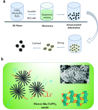
In this study, a flower-like FePO4 material was synthesized using the sol–gel and hydrothermal reaction. Owing to the low electronic conductivity of FePO4, these materials can reduce the pathway for electrons and ions, and the detailed process is presented in Fig. 1a. The FePO4 was synthesized by mixing FeSO4 with (NH4)H2PO4 with the addition of ascorbic acid and PEG-400 in a microwave reactor. Then, the solution was heated by hydrothermal reaction at 180 °C. Finally, the precipitate was calcined at 380 °C for 6 h in a muffle furnace to obtain the well-dispersed FePO4. It should be noted that FePO4 can be used as a precursor for the synthesis of LiFePO4 and has extremely low costs and a simple synthesis procedure. A schematic diagram of this material is shown in Fig. 1b. It shows a flower-like and strange structure with a regular arrangement of petal-like flakes, which are completely different from the previous particle or core–shell materials. This special structure can provide many pores and short pathways to enable the fast transfer of ions and electrons. Thus, the material includes a larger number of pores in the crimped micro-nanostructure, as shown in Fig. 2. In addition, the pores can absorb the electrolyte in advance and decrease the interface polarization. In these materials, the super-thick electrode was obtained as a result of the special structure maintaining sufficient amounts of the electrolyte in the pores. Fig. 2d shows the X-ray diffraction (XRD) pattern for this material. All the peaks of the FePO4 structure correspond to the standard characteristic peaks reported for FePO4 [JCPDS19-0721], and it can be seen that the composite material contains the characteristic peaks for FePO4, such as 26.5°, 43°, and 52°, attributed to the phases of (002), (100), (101) and (004), respectively. The particle size is mainly distributed between 100–500 nm, and the D50 is about 200 nm. These nanoscale materials can ensure electron and ion transportation under a coating electrode with a high weight, which meets the needs for industrialization.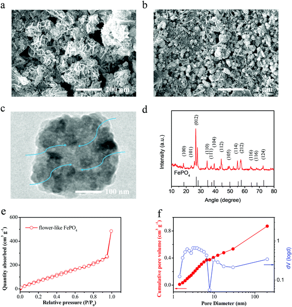 | ||
| Fig. 2 (a) and (b) SEM images, (c) TEM images and (d) XRD spectra of the flower-like FePO4. (e) and (f) The nitrogen adsorption–desorption curves of the prepared FePO4 materials. | ||
Fig. 2e and f shows the nitrogen adsorption–desorption curves of the prepared FePO4 materials. The curve demonstrates type-IV characteristics and a hysteresis loop of type-H3 under high pressure, thus it indicates that there are two kinds of voids, mesopores and micropores. This is closely related to the flower-like structure of this material. These materials demonstrate a high SSA (∼186 m2 g−1). Fig. 2f shows the cumulative pore volume for the Barrett–Joyner–Halenda (BJH) pore size distribution curves. It can be seen that the FePO4 presents a larger number of micropores and mesopores. There is a wider peak for the pore size at 1–100 nm, which results from the tensile strength of nitrogen desorption. This result again shows that the pore size distribution and expected characteristics are in line with the design characteristics of a flower-like structure.
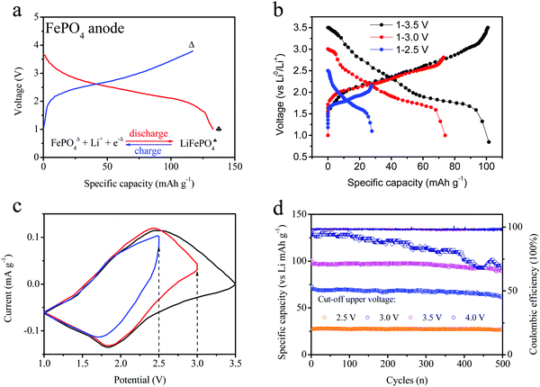
Herein, this FePO4 material was used as an anode electrode in order to investigate its properties, as shown in Fig. 3a. Furthermore, the charge–discharge curves (intercalation–deintercalation) of FePO4 for anode electrodes with LiPF6 and PC:EMC are also shown in the figure. The FePO4 material was able to intercalate the lithium ions, hence their electrochemical properties as an anode electrode in a half-cell were measured, and the voltage ranged from 1 to 3.8 V. The voltage presents wide platform changes, which are different from the previous curves obtained for the LiFePO4 cathode. The main reason is attributed to the similar amorphous phase structure. The FePO4 materials show an ideal lithium-storage capability, changing to LiFePO4 during the charge-transfer process. To improve the stability of FePO4 in full batteries, lower voltage platforms are necessary through the partial electrochemical reaction of the FePO4 anode. Hence, we tailored the cut-off potential of the FePO4 anode in order to study the voltage and cycles curves. The charge–discharge curves and cyclic voltammetry profiles of the different electrodes are shown in Fig. 3b and c. The three curves exhibit quite different charge capacities and voltage platforms under different voltage windows. In addition, these half-cells were scanned in the voltage ranges of 3.5, 3.0 and 2.5 V, respectively. Similar peaks were noticed, including the reduction peak at 1.8 and the oxidation peak at 2.5 V. When the voltage was cut off at 2.5 V, the electrode only showed a half peak at 2.5 V, indicative of the incomplete electrochemical reaction and illustrating the partial lithium insertion–extraction owing to lower voltage platform.
Cycling was conducted at different voltage ranges and the results are depicted in Fig. 3d. In the different voltage ranges, the FePO4 shows a different reversible capacity and cyclic trend. At the initial stage, the charge capacity was up to 130 mA h g−1 owing to the deep insertion–extraction reaction of the anode materials. As the electrochemical processes occurred repeatedly, the cycling capacity led to certain fading changes. After 500 cycles, this capacity loss reached 95 mA h g−1. At a voltage window of 1.0–3.0 V, the specific capacity was recorded at about 100 mA h g−1. However, it was relatively stable and a reversible capacity of 95 mA h g−1 was obtained after 500 cycles. For the FePO4 electrode, a specific capacity of about 71 mA h g−1 was obtained at 1.0–2.5 V. Thus, the cutoff range for the voltage is associated with the partial lithiation reaction of FePO4. After 500 cycles, the capacity became quite stable with a loss rate below 2%. For the three types of FePO4 electrode, the coulombic efficiencies were basically above 96%. Therefore, a more stable cycling performance can be obtained by controlling the upper voltage of the FePO4 electrode, such as a range of 1.0–2.5 V.
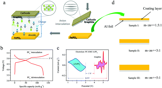
Even though the voltage platform was decreased in the different voltage windows, the FePO4 electrode still showed a voltage above 1 V, which limits its application in lithium ion batteries with a high energy density owing to requirement for a voltage below 4.5 V for the cathode electrode. However, as is known, DIBs often display a high voltage window above 5.4 V. Full batteries with a high voltage will affect the electrochemical stability and increase the difficulty of selecting an electrolyte. An ideal way to reduce this effect is using an anode material with a higher voltage platform. A schematic representation of the DIBs is shown in Fig. 4a. Unlike the “rocking-chair” structure of LIBs, the stored energy in DIBs is obtained by inserting anions and cations from the electrolyte onto both the cathode and anode at the same time. The ions are then extracted simultaneously into the electrolyte during discharge.
Currently, layered graphite is considered to be the most ideal material with an excellent electrochemical performance. For graphite cathodes, previous studies have shown that the layered material can store anions of PF6− to form C6(PF6−)n in a LiPF6-based electrolyte. The material demonstrates excellent anion intercalation properties with a voltage window above 5.4 V. However, it is difficult for the current electrolyte systems to withstand oxidation decomposition under such voltages, causing degradation of their lifetime. If the maximum intercalation voltage of the cathode electrode is controlled, the specific capacity will be significantly reduced. Thus, anodes with promising voltage platforms are critical to the application of DIBs. The FePO4 can act as a host to store the dissociated Li-ions from the electrolyte, mainly providing an appropriate voltage platform over 1 V (vs. Li0/Li+).
Fig. 4b represents the electrochemical profile of PF6− stored in layered graphite in the LiPF6 electrolyte. The reversible deintercalation of PF6− anions was attributed to the reversible capacity of 125–128 mAh g−1 between 3.5–5.45 V. It is almost impossible for the currently available electrolytes, such ethylene carbonate (EC), PC, EMC, diethyl carbonate (DEC) and so on, to endure a high voltage. In previous studies, an ionic liquid was often used to avoid this issue, but the use of these materials increases the costs and decreases the rate performance owing to the high viscosity of ionic liquids. Therefore, the FePO4 material was used as an anode to provide a rational design for complete DIBs. Fig. 4c displays both the CV curves of the graphite cathode and the FePO4 anode at the same time. A maximum voltage of 4.4 V and a minimum voltage range of 1 V can be observed during simultaneous intercalation and deintercalation for the anions and cations. Owing to the elevated electrochemical platform of anode electrodes, the ideal voltage range was obtained to prove the feasibility of this electrochemical system for use in DIBs.
For the FePO4 electrode, we prepared both thicknesses of the electrode of FePO4, as shown in Fig. 4d. The excess of coating mass for the anode material can achieve a lower voltage platform and a stable electrochemical performance. The super-thick electrodes were coated by precisely controlling the thickness using a scraper, as shown in Fig. 4d. Three electrodes of different thicknesses were designed, including loading mass ratios of the anode to the cathode (m−/m+) of: 1.5![[thin space (1/6-em)]](https://www.rsc.org/images/entities/char_2009.gif) :
:![[thin space (1/6-em)]](https://www.rsc.org/images/entities/char_2009.gif) 1, 3
1, 3![[thin space (1/6-em)]](https://www.rsc.org/images/entities/char_2009.gif) :
:![[thin space (1/6-em)]](https://www.rsc.org/images/entities/char_2009.gif) 1 and 5
1 and 5![[thin space (1/6-em)]](https://www.rsc.org/images/entities/char_2009.gif) :
:![[thin space (1/6-em)]](https://www.rsc.org/images/entities/char_2009.gif) 1.
1.
In full batteries, the lithium extraction depth of the electrodes could be achieved by adjusting the loading mass of the active material in both the anode and cathode electrodes. In industrial LIBs, the specific capacity of the anode is always higher than that of the cathode in order to achieve full use of the cathode material and prevent lithium precipitation on the anode surface. Three types of full DIBs were assembled with (−) FePO4|graphite (+) at loading mass ratios for the anode to cathode (m−/m+) of 1.5![[thin space (1/6-em)]](https://www.rsc.org/images/entities/char_2009.gif) :
:![[thin space (1/6-em)]](https://www.rsc.org/images/entities/char_2009.gif) 1, 3
1, 3![[thin space (1/6-em)]](https://www.rsc.org/images/entities/char_2009.gif) :
:![[thin space (1/6-em)]](https://www.rsc.org/images/entities/char_2009.gif) 1 and 5
1 and 5![[thin space (1/6-em)]](https://www.rsc.org/images/entities/char_2009.gif) :
:![[thin space (1/6-em)]](https://www.rsc.org/images/entities/char_2009.gif) 1, respectively. The charge–discharge curves of the full DIBs in the voltage range of 1–4.5 V are shown in Fig. 5a. All charging curves showed the same trend, but different voltage platforms were observed during changing. The graphite electrode depicted a higher lithiation plateau of 5
1, respectively. The charge–discharge curves of the full DIBs in the voltage range of 1–4.5 V are shown in Fig. 5a. All charging curves showed the same trend, but different voltage platforms were observed during changing. The graphite electrode depicted a higher lithiation plateau of 5![[thin space (1/6-em)]](https://www.rsc.org/images/entities/char_2009.gif) :
:![[thin space (1/6-em)]](https://www.rsc.org/images/entities/char_2009.gif) 1 for the full batteries. During discharge, the reversible curves indicated the same differences in voltage, with values of 2.38, 2.61 and 3.04 V in the middle capacity, respectively.
1 for the full batteries. During discharge, the reversible curves indicated the same differences in voltage, with values of 2.38, 2.61 and 3.04 V in the middle capacity, respectively.
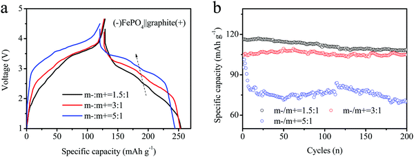 | ||
| Fig. 5 (a) Charge–discharge curves and (b) cycling performances of different batteries assembled using various loading masses (anode coating weight/cathode coating weight, record as m−/m+) for DIBs. | ||
The cycling performances of the electrodes are shown in Fig. 5b. The initial capacities of the three electrodes were estimated as 118.6, 113.2 and 105.4, respectively. Although the early stages looked similar, the characteristics gradually differed. The cycling capacity at m−/m+ = 1.5/1 rapidly decreased after the first 20 cycles, and the last capacity maintained only 85 mA h g−1 after 200 cycles. At the same time, the other electrodes maintained a stable cyclic capacity (m−/m+ =3/1 or 5/1). The constant fade rate was estimated to be less than 5%. However, the capacity of the m−/m+ = 5/1 electrode decayed rapidly during the initial stage and remained relatively stable until 75 mA h g−1 after 20 cycles. The electrode capacity was still 68 mA h g−1 after 200 cycles. The cyclic curves also remained stable for both samples of 1.5![[thin space (1/6-em)]](https://www.rsc.org/images/entities/char_2009.gif) :
:![[thin space (1/6-em)]](https://www.rsc.org/images/entities/char_2009.gif) 1 and 3
1 and 3![[thin space (1/6-em)]](https://www.rsc.org/images/entities/char_2009.gif) :
:![[thin space (1/6-em)]](https://www.rsc.org/images/entities/char_2009.gif) 1 but the rapid fading for the 5
1 but the rapid fading for the 5![[thin space (1/6-em)]](https://www.rsc.org/images/entities/char_2009.gif) :
:![[thin space (1/6-em)]](https://www.rsc.org/images/entities/char_2009.gif) 1 sample resulted from the over thickness of FePO4 electrodes.
1 sample resulted from the over thickness of FePO4 electrodes.
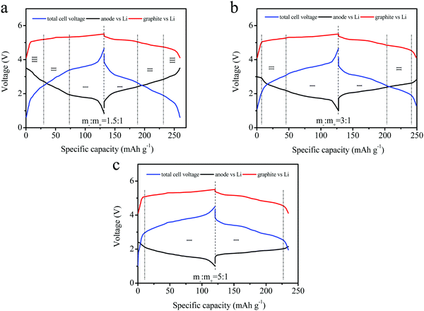
The tri-electrode curves for different full-batteries were measured to further study the voltage changes of the cathode and anode electrodes. The different electrodes included m−/m+ = 1.5/1, 3/1 and 5/1 (Fig. 6a–c). All three batteries exhibited similar charge–discharge voltage windows for the positive electrode (vs. reference electrode). The cut-off voltage of the positive electrode reached 5.52 V at a mass ratio of m−/m+ = 5/1, as well as 5.45 and 5.48 V at m−/m+ = 1.5/1 and 3/1 electrodes, respectively. The reason was attributed to an insufficient amount of the active materials and the same specific capacity. The charge–discharge curves of the anode (vs. reference electrode) were obviously different for these three curves. This mainly resulted from the different ratios employed in the three electrodes. Excess active material in the full batteries might lead to partial lithium insertion, and an increase in the FePO4 ratio relative to the cathode would rapidly decrease the voltage platform for the anode. The lower charging voltage platform of the anode (vs. reference electrode) during discharge was also observed in the full batteries, and higher voltage plateaus for the full batteries were obtained, as shown in Fig. 6c.
To further analyze the voltage platforms, the charge–discharge processes of the three electrode types in full batteries were recorded and the results are displayed in Fig. 7a and b. The voltage platform for the cathode/anode electrode (solid point) depicted an obvious difference. The electrode with an elevated loading mass presented a higher voltage platform, consistent with the results shown in Fig. 6a–c. During cycling, the voltage platform values increased for all three batteries. Meanwhile, the battery voltage with a low loading mass rose significantly according to the loading mass, and the voltage maintained a relatively stable value. A comparison of the full batteries revealed that the voltage platforms of the anode-reference electrode followed the opposite trend. The higher loading mass showed a more stable voltage value. The reason for this might be the better reversibility of lithiation at the electrodes with a high loading mass owing to partial lithium intercalation. Moreover, the depth of lithium intercalation for the FePO4 anode reduced the capacity retention ratio of the batteries. In Fig. 7b, the variation in the trend for the discharge voltage platform remained similar to that of the charging voltage. The enhancement in the loading mass of the anode could not only improve the cycling performance of the materials, but also provide batteries with high discharge voltages and elevated energy densities. Electrochemical impedance spectroscopy (EIS) was conducted to verify the changes at the interface of the electrode for the DIBs in Fig. 7c and d. The electrode (m−/m+ = 1.5/1) shows a more stable interface impedance relative to the other electrodes (3![[thin space (1/6-em)]](https://www.rsc.org/images/entities/char_2009.gif) :
:![[thin space (1/6-em)]](https://www.rsc.org/images/entities/char_2009.gif) 1 and 5
1 and 5![[thin space (1/6-em)]](https://www.rsc.org/images/entities/char_2009.gif) :
:![[thin space (1/6-em)]](https://www.rsc.org/images/entities/char_2009.gif) 1). Furthermore, the changes of electrode (m−/m+ = 3
1). Furthermore, the changes of electrode (m−/m+ = 3![[thin space (1/6-em)]](https://www.rsc.org/images/entities/char_2009.gif) :
:![[thin space (1/6-em)]](https://www.rsc.org/images/entities/char_2009.gif) 1) can be also accepted owing to without obvious increasing of impedance. This reason is attributed to the excellent flower-like structure that ensures a sufficient pathway is available for the electron and ions.
1) can be also accepted owing to without obvious increasing of impedance. This reason is attributed to the excellent flower-like structure that ensures a sufficient pathway is available for the electron and ions.
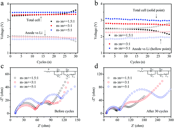 | ||
| Fig. 7 (a) Charge and (b) discharge voltage platforms during cycling of three types of DIBs assembled using different loading masses. (c) and (d) The EIS curves for the DIBs before and after cycling. | ||
Based on batteries with different loading masses, the best ratio for the anode:cathode was determined to be 3![[thin space (1/6-em)]](https://www.rsc.org/images/entities/char_2009.gif) :
:![[thin space (1/6-em)]](https://www.rsc.org/images/entities/char_2009.gif) 1. Fig. 8a exhibits the cycling performances of the full batteries of (−) FePO4‖graphite (+). The batteries delivered a charge capacity of 115 mA h g−1 and a discharge capacity of 105 mAh g−1 during the initial stage. The coulombic efficiency (CE) only reached 91.3% and can be attributed to the irreversible anion intercalation into the layered graphite material (C → C (PF6−)n). In addition, the discharge capacity slightly increased during the first 10 cycles, and the CE increased to approximately 96%. This suggested that the irreversible anion in the intercalation compounds can be extracted into the electrolyte. During the following cycles, the charge and discharge capacities remained stable without an obvious decrease. After 500 cycles, a high capacity of over 100 mA h g−1 can still be obtained with a CE of around 96%. The charge–discharge curves for different cycles (1, 5, 50, 100, and 500 cycles) are presented in Fig. 8b, corresponding to the cycling results shown in Fig. 7a. The capacity remained stable and the charge capacity was slightly reduced. The voltage plateau decreased from 1 to 500 cycles. A plateau at about 3 V appeared with an obvious depression from 3 V (1 cycle) to 2.9 V (500 cycles). A voltage platform fade of over 0.1 V was observed in the electrochemical performances after cycling. The voltage changes obtained during charging were larger than those recorded during the discharge. This was attributed to the high resistance of the anion intercalation in layered-graphite. However, the capacity was not affected owing to the relatively wide charge–discharge voltage window. Fig. 8c shows the rate capacities of the full batteries under different current densities of 50, 100, 200, 500, 1000, and back to 50 mA g−1. The specific capacity remained ideal under higher current densities. The capacity retention reached 92%, 88%, 84%, and 76% at 100, 200, 500, and 1000 cycles, respectively. Note that a value of 50 mA g−1 was observed at the beginning, and a remarkable recovery was observed after 50 cycles.
1. Fig. 8a exhibits the cycling performances of the full batteries of (−) FePO4‖graphite (+). The batteries delivered a charge capacity of 115 mA h g−1 and a discharge capacity of 105 mAh g−1 during the initial stage. The coulombic efficiency (CE) only reached 91.3% and can be attributed to the irreversible anion intercalation into the layered graphite material (C → C (PF6−)n). In addition, the discharge capacity slightly increased during the first 10 cycles, and the CE increased to approximately 96%. This suggested that the irreversible anion in the intercalation compounds can be extracted into the electrolyte. During the following cycles, the charge and discharge capacities remained stable without an obvious decrease. After 500 cycles, a high capacity of over 100 mA h g−1 can still be obtained with a CE of around 96%. The charge–discharge curves for different cycles (1, 5, 50, 100, and 500 cycles) are presented in Fig. 8b, corresponding to the cycling results shown in Fig. 7a. The capacity remained stable and the charge capacity was slightly reduced. The voltage plateau decreased from 1 to 500 cycles. A plateau at about 3 V appeared with an obvious depression from 3 V (1 cycle) to 2.9 V (500 cycles). A voltage platform fade of over 0.1 V was observed in the electrochemical performances after cycling. The voltage changes obtained during charging were larger than those recorded during the discharge. This was attributed to the high resistance of the anion intercalation in layered-graphite. However, the capacity was not affected owing to the relatively wide charge–discharge voltage window. Fig. 8c shows the rate capacities of the full batteries under different current densities of 50, 100, 200, 500, 1000, and back to 50 mA g−1. The specific capacity remained ideal under higher current densities. The capacity retention reached 92%, 88%, 84%, and 76% at 100, 200, 500, and 1000 cycles, respectively. Note that a value of 50 mA g−1 was observed at the beginning, and a remarkable recovery was observed after 50 cycles.
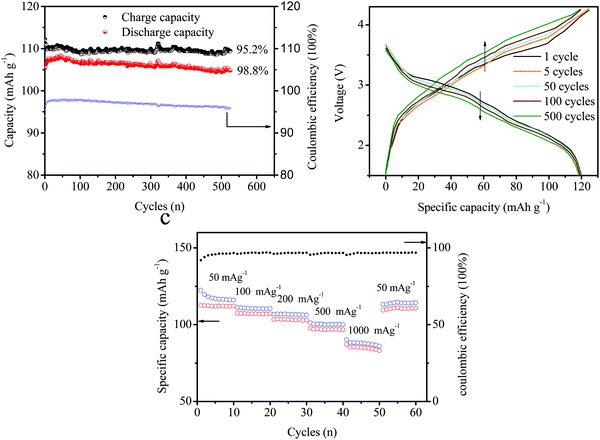 | ||
| Fig. 8 (a) Cycling performances of the full batteries. (b) Charge–discharge curves at different cycles (1, 5, 50, 100, and 500 cycles) and (c) at different cycling rates. | ||
4. Conclusions
Based on the graphite cathode, DIBs exhibit excellent advantages in terms of high safety properties and low costs for next generation energy storage devices. However, it is difficult for the electrolyte to withstand oxidative decomposition above 5 V. Here, a novel flower-like FePO4 anode was proposed for pairing with graphite-based DIBs. As a precursor for the LiFePO4 material, FePO4 showed obvious advantages in terms of the structural stability and is also low-cost, and exhibited an extended electrochemical window of 1–3.5 V. In full batteries, a suitable voltage window was obtained owing to the wide 1–3.5 V voltage range. To further improve the voltages of full batteries, different loading mass ratios for the anode/cathode were investigated and it was determined that 3 V was the best value. In addition, the PC–EMC solvent was selected as an electrolyte. Overall, these findings show promise for industrial applications in low-cost DIBs with a high energy density.Conflicts of interest
There are no conflicts to declare.Acknowledgements
This work was financially supported by Natural Science Foundation of Guangdong Province of China (2017A030313261), the Guangdong Innovation Research Team for High Education (2017KCXTD030), High-level Talents Project of Dongguan University of Technology (KCYKYQD2017017) and the Research start-up funds of DGUT (GC300502-34).References
- B. Lee, Y. Ko, G. Kwon, S. Lee, K. Ku, J. Kim and K. Kang, Joule, 2018, 2, 61–75 CrossRef CAS.
- J.-Y. Hwang, S.-T. Myung and Y.-K. Sun, Chem. Soc. Rev., 2017, 46, 3529 RSC.
- D. Larcher and J. M. Tarascon, Nat. Chem., 2015, 7, 19–29 CrossRef CAS PubMed.
- M. K. Liu, P. Zhang, Z. H. Qu, Y. Yan, C. Lai, T. X. Liu and S. Q. Zhang, Nat. Commun., 2019, 10, 3917 CrossRef PubMed.
- Y. Yan, P. Zhang, Z. H. Qu, M. Tong, S. Zhao, Z. W. Li, M. K. Liu and Z. Q. Lin, Nano Lett., 2020, 20, 7662–7669 CrossRef CAS PubMed.
- S. Altin, S. Demirel, E. Oz, E. Altin, C. Hetherington, A. Bayri and S. Avci, CrystEngComm, 2020, 22, 2483–2490 RSC.
- S.-I. Tobishima and J.-I. Yamaki, J. Power Sources, 1999, 81-82, 882–886 Search PubMed.
- Y. Yan, H. Y. Cheng, Z. H. Qu, R. Yu, F. Liu, Q. W. Ma, S. Zhao, H. Hu, Y. Cheng, C. Y. Yang, Z. F. Li, X. Wang, S. Y. Hao, Y. Y. Chen and M. K. Liu, J. Mater. Chem. A, 2021, 9, 19489–19507 RSC.
- B. M. Li, Y. Yan, C. T. Shen, Y. Yu, Q. H. Wang and M. K. Liu, Nanoscale, 2018, 10, 16217–16230 RSC.
- S. Zhao, Y. Kang, M. J. Liu, B. H. Wen, Q. Fang, Y. Y. Tang, S. C. He, X. Ma, M. K. Liu and Y. Yan, J. Mater. Chem. A, 2021, 9, 18927–18946 RSC.
- C. Li, T. S. Shi, D. C. Li, H. Yoshitake and H. Y. Wang, J. Power Sources, 2016, 335, 38–44 CrossRef CAS.
- T. M. Bandhauer, S. Garimella and T. F. Fuller, J. Electrochem. Soc., 2011, 158(3), R1–R25 CrossRef CAS.
- W. C. West, J. F. Whitacre, N. Leifer, S. Greenbaum, M. Smart, R. Bugga, M. Blanco and S. R. Narayanan, J. Electrochem. Soc., 2007, 154, A929–A936 CrossRef CAS.
- M. Noel and R. Santhanam, J. Power Sources, 1998, 72, 53–65 CrossRef CAS.
- J. O. Besenhard and H. P. Fritz, Angew. Chem., Int. Ed. Engl., 1983, 22, 950–975 CrossRef.
- T. Placke, O. Fromm, S. F. Lux, P. Bieker, S. Rothermel, H. W. Meyer, S. Passerini and M. Winter, J. Electrochem. Soc., 2012, 159, A1755–A1765 CrossRef CAS.
- T. Placke, P. Bieker, S. F. Lux, O. Fromm, H. W. Meyer, S. Passerini and M. Winter, Z. Phys. Chem., 2012, 226, 391–407 CrossRef CAS.
- R. T. Carlin, H. C. Delong, J. Fuller and P. C. Trulove, J. Electrochem. Soc., 1994, 141, L73–L76 CrossRef CAS.
- W. C. West, J. F. Whitacre, N. Leifer, S. Greenbaum, M. Smart, R. Bugga, M. Blanco and S. R. Narayanan, J. Electrochem. Soc., 2007, 154, A929–A936 CrossRef CAS.
- R. T. Carlin, H. C. Delong, J. Fuller and P. C. Trulove, J. Electrochem. Soc., 1994, 141, L73–L76 CrossRef CAS.
- J. A. Read, J. Phys. Chem. C, 2015, 119, 8438–8446 CrossRef CAS.
- J. Fan, Z. Zhang, Y. Liu, A. Wang, L. Li and W. Yuan, Chem. Commun., 2017, 53, 6891–6894 RSC.
- J. A. Seel and J. R. Dahn, J. Electrochem. Soc., 2000, 147, 892–898 CrossRef CAS.
- S. Rothermal, P. Meister, G. Schmuelling, O. Fromm, H. W. Meyer, S. Norwak, M. Winter and T. Placke, Energy Environ. Sci., 2014, 7, 3412–3423 RSC.
- K. V. Kravchyk, S. Wang, L. Piveteau and M. V. Kovalenko, Chem. Mater., 2017, 29, 4484–4492 CrossRef CAS.
- G. Schmuelling, T. Placke, R. Kloepsch, O. Fromm, H. W. Meyer, S. Passerini and M. Winer, J. Power Sources, 2013, 239, 563–571 CrossRef CAS.
- S. Rothermel, P. Meister, G. Schmuelling, O. Fromm, H. W. Meyer, S. Nowak, M. Winter and T. Placke, Energy Environ. Sci., 2014, 7, 3412–3423 RSC.
- S. Rothermel, P. Meister, O. Fromm, J. Huesker, H. W. Meyer, M. Winter and T. Placke, ECS Trans., 2014, 58, 15–25 CrossRef.
- C. P. Han, H. F. Li, Y. Li, J. X. Zhu and C. Y. Zhi, Nat. Commun., 2021, 12, 2400 CrossRef CAS PubMed.
- L. Fan, Q. Liu, S. Chen, Z. Xu and B. Lu, Adv. Energy Mater., 2017, 7, 1602778–1602785 CrossRef.
- K. Beltrop, S. Beuker, A. Heckmann, M. Winter and T. Placke, Energy Environ. Sci., 2017, 10, 2090–2094 RSC.
- F. Zhang, B. Ji, X. Tong, M. Sheng, X. Zhang, C.-S. Lee and Y. Tang, Adv. Mater. Interfaces, 2016, 3, 1600605–1600611 CrossRef.
- J. Fan, Z. Zhang, Y. Liu, A. Wang, L. Li and W. Yuan, Chem. Commun., 2017, 53, 6891–6894 RSC.
- T. Placke, O. Fromm, S. F. Lux, P. Bieker, S. Rothermel, H. W. Meyer, S. Passerini and M. Winter, J. Electrochem. Soc., 2012, 159, A1755–A1765 CrossRef CAS.
- S. Rothermel, P. Meister, O. Fromm, J. Huesker, H. W. Meyer, M. Winter and T. Placke, ECS Trans., 2014, 58, 15–25 CrossRef.
- M. B. Pinson and M. Z. Bazant, J. Electrochem. Soc., 2013, 160(2), A243–A250 CrossRef CAS.
- C. P. Han, L. Xu, H. F. Li, R. Y. Shi, T. F. Zhang, J. Q. Li, C.-P. Wong, F. Y. Kang and Z. Q. Lin, Carbon, 2018, 140, 296–305 CrossRef CAS.
- A. K. Padhi, K. S. Nanjundaswamy and J. B. Goodenough, J. Electrochem. Soc., 1997, 144, 1188–1194 CrossRef CAS.
- Z. C. Shi, A. Sttia, W. L. Ye, Q. Wang, Y. X. Li and Y. Yang, Electrochim. Acta, 2008, 53, 2665–2673 CrossRef CAS.
- R. Cai, Y. Du, W. Zhang, H. Tan, T. Zeng, X. Huang, H. Yang, C. Chen, H. Liu, J. Zhu, S. Peng, J. Chen, Y. Zhao, H. Wu, Y. Huang, R. Xu, T. Lim, Q. Zhang, H. Zhang and Q. Yan, Chem. – Eur. J., 2013, 19, 1568–1572 CrossRef CAS PubMed.
- H. M. Lv, S. Yang, C. Li, C. P. Han, Y. C. Tang, X. J. Li, W. L. Wang, H. F. Li and C. Y. Zhi, Energy Storage Mater., 2020, 31, 451–458 CrossRef.
- P. P. Prosini, M. Lisi, S. Scaccia, M. Carewska, F. Cardellini and M. Pasquali, J. Electrochem. Soc., 2002, 149, A297–A301 CrossRef CAS.
- Y. S. Hong, K. Ryu, Y. J. Park, M. G. Kim, J. M. Lee and S. H. Chang, J. Mater. Chem., 2002, 12, 1870–1874 RSC.
- T. B. Zhang, X.-B. Cheng, Q. Zhang, Y. C. Lu and G. S. Luo, J. Power Sources, 2016, 324, 52–60 CrossRef CAS.
- T. C. Liu, Y. C. Feng, Y. D. Duan, S. H. Cui, L. P. Lin, J. T. Hu, H. Guo, Z. Q. Zhuo, J. X. Zheng, Y. Lin, W. L. Yang, K. Amine and F. Pan, Nano Energy, 2015, 18, 187–195 CrossRef CAS.
- Y. Zhang, Y. Tang, L. Liu, T. Yang, X. Wang and Z. Zhao, CrystEngComm, 2020, 22, 2429–2433 RSC.
- R. Dedryvère, M. Maccario, L. Croguennec, F. LeCras, C. Delmas and D. Gonbeau, Chem. Mater., 2008, 20, 7164–7170 CrossRef.
- K. Galoustov, M. Anthonisen, D. H. Ryan and D. D. MacNeil, J. Power Sources, 2011, 196, 6893–6897 CrossRef CAS.
- X.-L. Wei, N. Li, J.-F. An, C.-F. Huo, H. Liu, R. Yang, X. Li and Z.-S. Chao, CrystEngComm, 2020, 22, 205–212 RSC.
| This journal is © The Royal Society of Chemistry 2021 |

