 Open Access Article
S, O dual-doped porous carbon derived from activation of waste papers as electrodes for high performance lithium ion capacitors†
Jian
Hao
 *a,
Jun
Bai
a,
Xiu
Wang
a,
Yanxia
Wang
a,
Qingjie
Guo
a,
Yu
Yang
b,
Jiupeng
Zhao
 b,
Caixia
Chi
b and
Yao
Li
 c
c
aState Key Laboratory of High-efficiency Utilization of Coal and Green Chemical Engineering, College of Chemistry & Chemical Engineering, Ningxia University, Yinchuan 750021, China. E-mail: haojian2017@126.com
bSchool of Chemical Engineering and Technology, Harbin Institute of Technology, 150001, Harbin, China
cCentre for Composite Materials, Harbin Institute of Technology, Harbin 150001, China
First published on 10th December 2020
Abstract
To circumvent the imbalances of electrochemical kinetics and charge-storage capacity between Li+ ion battery anodes and capacitive cathodes in lithium-ion capacitors (LICs), dual carbon based LICs are constructed and investigated extensively. Herein, S, O dual-doped 3D net-like porous carbon (S-NPC) is prepared using waste paper as the carbon source through a facile solvothermal treatment and chemical activation. Benefiting from the combination effect of the rich S,O-doping (about 2.1 at% for S, and 9.0 at% for O), high surface area (2262 m2 g−1) and interconnected porous network structure, the S-NPC-40 material exhibits excellent electrochemical performance as both cathode material and anode material for LICs. S, O doping not only increases the pseudocapacity but also improves the electronic conductivity, which is beneficial to reduce the mismatch between the two electrodes. The S-NPC-40//S-NPC-40 LIC delivers high energy densities of 176.1 and 77.8 W h kg−1 at power densities of 400 and 20 kW kg−1, respectively, as well as superior cycling stability with 82% capacitance retention after 20![[thin space (1/6-em)]](https://www.rsc.org/images/entities/char_2009.gif) 000 cycles at 2 A g−1. This research provides an efficient method to convert waste paper to porous carbon electrode materials for high performance LIC devices.
000 cycles at 2 A g−1. This research provides an efficient method to convert waste paper to porous carbon electrode materials for high performance LIC devices.
Introduction
The escalating energy crisis and environmental degradation call for developing sustainable, renewable and highly efficient energy storage technologies.1–3 Lithium ion capacitors (LICs), which originate from the hybrid of Li ion batteries (LIBs) and supercapacitors (SCs), integrate the merits of high energy and power densities, and provide excellent energy, power density, and long cycling performances.4,5 LICs are considered to be a promising candidate for meeting the growing demand in the energy storage field. In a typical LIC, the cathode is usually made from commercial activated carbon (AC) which offers fast charge/discharge performance and excellent cyclability, while the Li ion intercalation anode provides high specific capacities.6,7 However, in this combination, a mismatch of the intrinsic kinetics and specific capacities exists between the anode and cathode (AC has a low capacity compared with battery-type anodes, and the electrode kinetics of Li ion intercalation/deintercalation in the anode is much slower than that of physical adsorption/desorption in the cathode), which results in large overpotentials in the cathode and limited high-capacity of the anode.8,9 In order to improve the electrochemical performance of LICs, many materials such as insertion-type materials (Li4Ti5O12, TiO2 and Nb2O5),10–12 conversion-type or alloying reaction materials (Fe2O3, MnO2, Sn and Si)13–16 are used as anodes for LICs. Unfortunately, the comparatively high redox operating voltage of metal oxides and the insufficient stability of the conversion-type (alloy-type) anode make them unsatisfactory in high-performance LICs.Porous carbon has attracted much attention because of its high surface area, good electronic conductivity, and excellent stability, making it an ideal candidate as an electrode material for high energy and power density energy storage devices.17–19 In recent years, LICs with both electrodes of the same material have begun to garner increasing interest. Carbon nanosheets20,21 and graphene22,23 have been used as both positive and negative electrode materials for LICs, which prevents electrode kinetics imbalance and also verifies the feasibility of symmetric electrode LICs. However, because of the limited theoretical capacity of carbon materials, the energy density of LICs is still unsatisfactory. Heteroatom doping is an efficient way to tune the chemical and physical characteristics of carbonaceous materials, it can produce defects and porosities, as well as increase the interlayer distance of carbon. B and N dual doping porous carbon nanofibers (BNC) exhibited greatly improved electrochemical performance both as cathode and anode;24 BNC//BNC LICs showed an energy density of 220 W h kg−1 and a high power density of 22.5 kW kg−1. Using N-doped porous carbon (NDPC) as the cathode and anode,25 the LIC (NDPC-0.5//NDPC-0.5) delivered an energy density of 87.7 W h kg−1 at a power density of 10![[thin space (1/6-em)]](https://www.rsc.org/images/entities/char_2009.gif) 000 W kg−1. By coupling a pre-lithiated N-doped carbon nanosphere (ANCS) anode with a fresh ANCS cathode,26 ANCS//ANCS LICs delivered high energy densities of 206.7 and 115.4 W h kg−1 at power densities of 0.225 and 22.5 kW kg−1, respectively. These results indicate that the heteroatom doping brings in pseudocapacitive behavior, improves electrical conductivity efficiently, increases surface wettability and accelerates charge transfer. The electrochemical performance of LICs could be effectively adjusted by controlling the heteroatom doping properties. The N or S atoms doped into the carbon skeleton may act as electron donors, which increases their supercapacitor behavior . It's worth noting that doping S with a bigger atomic radius and lower electronegativity helps in the enlargement of the graphite layer spacing of carbon and facilitates ion transfer. Bo Quan et al.27 synthesized S-doped graphene (S-SG) which exhibited a high reversible capacity of 380 mA h g−1 after 300 cycles at 100 mA g−1. Sheng-xue Yan et al.3 prepared a sulfur self-doped 3D hierarchical porous carbon (S-3DHPC) symmetric supercapacitor, which exhibited an energy density of 17.8 W h kg−1 at a power density of 652 W kg−1. Ling Chen et al.28 demonstrated that S doping could lead to extra quantum capacitance and suppress the side reactions; the bigger S atoms could enlarge the interlayer distance of carbon, accelerating ion diffusion kinetics. Thus, it is highly desirable to develop a facile strategy for the design and preparation of heteroatom doped porous carbon from green and low cost raw materials, which is crucial for the widespread application of LICs.
000 W kg−1. By coupling a pre-lithiated N-doped carbon nanosphere (ANCS) anode with a fresh ANCS cathode,26 ANCS//ANCS LICs delivered high energy densities of 206.7 and 115.4 W h kg−1 at power densities of 0.225 and 22.5 kW kg−1, respectively. These results indicate that the heteroatom doping brings in pseudocapacitive behavior, improves electrical conductivity efficiently, increases surface wettability and accelerates charge transfer. The electrochemical performance of LICs could be effectively adjusted by controlling the heteroatom doping properties. The N or S atoms doped into the carbon skeleton may act as electron donors, which increases their supercapacitor behavior . It's worth noting that doping S with a bigger atomic radius and lower electronegativity helps in the enlargement of the graphite layer spacing of carbon and facilitates ion transfer. Bo Quan et al.27 synthesized S-doped graphene (S-SG) which exhibited a high reversible capacity of 380 mA h g−1 after 300 cycles at 100 mA g−1. Sheng-xue Yan et al.3 prepared a sulfur self-doped 3D hierarchical porous carbon (S-3DHPC) symmetric supercapacitor, which exhibited an energy density of 17.8 W h kg−1 at a power density of 652 W kg−1. Ling Chen et al.28 demonstrated that S doping could lead to extra quantum capacitance and suppress the side reactions; the bigger S atoms could enlarge the interlayer distance of carbon, accelerating ion diffusion kinetics. Thus, it is highly desirable to develop a facile strategy for the design and preparation of heteroatom doped porous carbon from green and low cost raw materials, which is crucial for the widespread application of LICs.
Waste office paper, especially shredded printed paper is an important component of collectable garbage in human daily life, available in large quantities globally.29 The sustainable and comprehensive utilization of waste office paper is important to tackle energy and environmental issues. Herein we developed a facile and effective synthesis of S, O-doped 3D net-like porous carbon (S-NPC) using shredded printed paper as the raw material. S-NPC-40 prepared via solvothermal treatment and high temperature pyrolysis for 40 min, shows a high surface area (2262 m2 g−1) and a high S/O doping content (about 2.1 at% for S, and 9.0 at% for O), and exhibits outstanding electrochemical performance both as the positive material and negative material for LICs. Inspiringly, by coupling a pre-lithiated S-NPC-40 anode with a fresh S-NPC-40 cathode, the obtained S-NPC-40//S-NPC-40 LIC shows a high operating voltage of 4.0 V, high energy density of 176.1 W h kg−1 at a power density of 400 W kg−1, and retains 77.8 W h kg−1 under a higher power of 20 kW kg−1. Moreover, the LIC shows excellent cyclability over 20![[thin space (1/6-em)]](https://www.rsc.org/images/entities/char_2009.gif) 000 cycles with 82% capacitance retention. These results not only offer a facile strategy for the construction of S-doped carbon materials, but also verify the feasibility of higher performance carbon-based materials for potential application in LICs.
000 cycles with 82% capacitance retention. These results not only offer a facile strategy for the construction of S-doped carbon materials, but also verify the feasibility of higher performance carbon-based materials for potential application in LICs.
Experimental
Material synthesis
Waste office papers (shredded printed A4 size paper) were used as the precursor for the synthesis of S-NPC. In a typical synthesis process, firstly, 2 g waste paper was added in 60 mL of 1 mol L−1 H2SO4. Then the mixture was transferred into a 100 mL Teflon-lined stainless steel autoclave and heated at 180 °C for 12 h. After cooling the autoclave to room temperature, the solvothermal product was washed with distilled water, and finally dried at 80 °C for 24 h. Secondly, the dried solvothermal paper was mixed with KOH and K2CO3 in a 1![[thin space (1/6-em)]](https://www.rsc.org/images/entities/char_2009.gif) :
:![[thin space (1/6-em)]](https://www.rsc.org/images/entities/char_2009.gif) 3
3![[thin space (1/6-em)]](https://www.rsc.org/images/entities/char_2009.gif) :
:![[thin space (1/6-em)]](https://www.rsc.org/images/entities/char_2009.gif) 0.2 mass ratio. The mixture was carbonized and activated using a tube furnace with an alumina tube at a temperature of 850 °C for a period of time in an atmosphere of N2. After cooling the furnace to room temperature, the as-obtained sample was washed with 1 mol L−1 HCl to remove any inorganic impurities. Finally, the samples were washed with abundant distilled water until pH about 7, and dried at 80 °C overnight. The samples activated for 40 and 60 min are denoted as S-NPC-40 and S-NPC-60, respectively. To investigate the effect of K2CO3 on the microstructure and electrochemical performance of porous carbon, porous carbon was also prepared with only KOH activated for 40 min and is denoted as S-NPC-KOH.
0.2 mass ratio. The mixture was carbonized and activated using a tube furnace with an alumina tube at a temperature of 850 °C for a period of time in an atmosphere of N2. After cooling the furnace to room temperature, the as-obtained sample was washed with 1 mol L−1 HCl to remove any inorganic impurities. Finally, the samples were washed with abundant distilled water until pH about 7, and dried at 80 °C overnight. The samples activated for 40 and 60 min are denoted as S-NPC-40 and S-NPC-60, respectively. To investigate the effect of K2CO3 on the microstructure and electrochemical performance of porous carbon, porous carbon was also prepared with only KOH activated for 40 min and is denoted as S-NPC-KOH.
Structural characterization
The morphological characterization of the as-prepared sample was performed with a Hitachi S-4800 scanning electron microscope (SEM) and a JEOL-2100F transmission electron microscope (TEM) at an acceleration voltage of 200 kV. Raman spectra were measured on an HR800 (Horiba Jobin Yvon) with a 514.5 nm laser source. XRD analysis of the sample was done using an XRD Bruker D8-ADVANCE. X-ray photoelectron spectroscopy (XPS) was performed using a Kratos XSAM 800 spectrometer (Manchester, UK). Nitrogen adsorption–desorption isotherms were obtained at 77 K on an Autosorb IQ Quantachrome Analyzer. Before the adsorption measurements, all samples were degassed at 200 °C for more than 6 h under high vacuum. The SSA was calculated by the Brunauer–Emmett–Teller (BET) method. The pore size distribution was analyzed by the nonlocal density functional theory (DFT) method.Electrochemical measurements
The electrochemical properties of all samples were characterized using 2032 coin-half cells. The electrode slurry was prepared by mixing the active materials (S-NPC-40, S-NPC-60, or S-NPC-KOH), acetylene black and poly(vinylidene fluoride) (PVDF) in the weight ratio of 8![[thin space (1/6-em)]](https://www.rsc.org/images/entities/char_2009.gif) :
:![[thin space (1/6-em)]](https://www.rsc.org/images/entities/char_2009.gif) 1
1![[thin space (1/6-em)]](https://www.rsc.org/images/entities/char_2009.gif) :
:![[thin space (1/6-em)]](https://www.rsc.org/images/entities/char_2009.gif) 1 in an N-methyl pyrrolidone (NMP) solvent. And subsequently, the as-obtained slurries were uniformly coated on Al foil and Cu foil as the cathode and anode, respectively. For assembling half cells, the as-prepared cathode or anode was used as the working electrode, lithium metal foil as the counter electrode, Celgard 2500 as the separator, and 1 mol L−1 LiPF6 in ethylene carbonate (EC)/dimethyl carbonate (DMC) (1
1 in an N-methyl pyrrolidone (NMP) solvent. And subsequently, the as-obtained slurries were uniformly coated on Al foil and Cu foil as the cathode and anode, respectively. For assembling half cells, the as-prepared cathode or anode was used as the working electrode, lithium metal foil as the counter electrode, Celgard 2500 as the separator, and 1 mol L−1 LiPF6 in ethylene carbonate (EC)/dimethyl carbonate (DMC) (1![[thin space (1/6-em)]](https://www.rsc.org/images/entities/char_2009.gif) :
:![[thin space (1/6-em)]](https://www.rsc.org/images/entities/char_2009.gif) 1 in volume) as the electrolyte. The galvanostatic charge discharge (GCD) measurements were performed in the voltage range of 2.0 and 4.5 V and 0.01–3.0 V (vs. Li/Li+) for the cathode and anode, respectively. A Neware battery test system (Shenzhen, China) was applied for the battery performance test. Cyclic voltammetry (CV) and electrochemical impedance spectroscopy (EIS) were conducted on an electrochemical workstation (CHI 660E).
1 in volume) as the electrolyte. The galvanostatic charge discharge (GCD) measurements were performed in the voltage range of 2.0 and 4.5 V and 0.01–3.0 V (vs. Li/Li+) for the cathode and anode, respectively. A Neware battery test system (Shenzhen, China) was applied for the battery performance test. Cyclic voltammetry (CV) and electrochemical impedance spectroscopy (EIS) were conducted on an electrochemical workstation (CHI 660E).
For the fabrication of the LIC device, the S-NPC anode was prelithiated in a half cell with Li foil at 0.1C for 5 cycles and, finally, lithiating to 1.0 V, and then the prelithiated S-NPC anodes were coupled with fresh S-NPC cathodes. The active material mass ratio of the anode and cathode is fixed at 1![[thin space (1/6-em)]](https://www.rsc.org/images/entities/char_2009.gif) :
:![[thin space (1/6-em)]](https://www.rsc.org/images/entities/char_2009.gif) 3, and the loading mass of the active material on the anode is around 1.0 mg cm−2. All the cells were assembled in an argon-filled glovebox with 1 mol L−1 LiPF6 in ethylene carbonate (EC)/dimethyl carbonate (DMC) (1
3, and the loading mass of the active material on the anode is around 1.0 mg cm−2. All the cells were assembled in an argon-filled glovebox with 1 mol L−1 LiPF6 in ethylene carbonate (EC)/dimethyl carbonate (DMC) (1![[thin space (1/6-em)]](https://www.rsc.org/images/entities/char_2009.gif) :
:![[thin space (1/6-em)]](https://www.rsc.org/images/entities/char_2009.gif) 1 in volume) as the electrolyte and Whatman glass fiber (GF/D) as the separator. The energy densities (E, W h kg−1) and power densities (P, W kg−1) of the LICs were calculated according to eqn (1) and (2).5,30
1 in volume) as the electrolyte and Whatman glass fiber (GF/D) as the separator. The energy densities (E, W h kg−1) and power densities (P, W kg−1) of the LICs were calculated according to eqn (1) and (2).5,30
 | (1) |
 | (2) |
Results and discussion
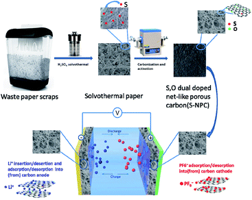
The S-NPC materials were prepared via a facile two-step method as illustrated in Fig. 1.In the preparation of S-NPC, solvothermal treatment is used to increase the S content of the raw materials, viz., waste paper. After high temperature carbonization and activation, heteroatoms (S and O) were doped into the carbon skeleton resulting in the formation of heteroatom functional groups on the carbon surface, and the solvothermal paper exhibited a porous structure. The S-NPC material was obtained through removing alkali and minerals from the activated samples. The SEM images of the as-prepared samples are shown in Fig. 2. After H2SO4 solvothermal treatment, the solvothermal paper shows 3D sheet morphology with many folds, and without a porous structure (Fig. 2a). After activation, S-NPC still maintains the 3D structure. Due to KOH etching, some pores are found on the carbon surface and the carbon structure appears bowl-like (Fig. 2b). The mechanism of pore formation has been described as the oxidation and reduction reaction of C on reaction with KOH, and the gasification of H2, H2O, CO, CO2. At low temperature some KOH dehydrates to potassium oxide (K2O) (eqn (3)). In addition, K2CO3 is formed (eqn (4)) during the reaction of KOH and C. And then the K2CO3 decomposes into K2O and CO2 at 700 °C (eqn (5)). At a higher activation temperature of 800 °C, previous intermediates K2CO3 and K2O may further react with C according to eqn (6) and (7). During the activation process, K2O and K2CO3 can corrode the carbon skeleton by an oxidation–reduction reaction, which is beneficial to the formation of a porous structure. And metallic K is intercalated into the carbon matrix; after removal of metallic K and other K compounds, a microporous structure with high specific surface area could be observed.3,31–33
| 2KOH → K2O + H2O | (3) |
| 6KOH + 2C → 2K + 3H2 + 2K2CO3 | (4) |
| K2CO3 → K2O + CO2 | (5) |
| K2CO3 + 2C → 2K + CO | (6) |
| K2O + C → 2K + CO | (7) |
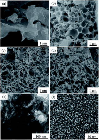 | ||
| Fig. 2 (a–d) SEM images of the solvothermal paper, S-NPC-KOH, S-NPC-40 and S-NPC-60, respectively, (e) TEM image of S-NPC-40, and (f) HRTEM image of S-NPC-40. | ||
With increasing K2CO3 in the activation process, reactions (5)–(7) are promoted, the bowl structure of the sample is gradually destroyed, part of the carbon wall disappears, and a net-like porous structure is formed (Fig. 2c). As shown in Fig. 2c and d, the internal porous architecture is constructed with the carbon nanowires, showing an intersectional open channel system. With increasing activation time, part of the pores collapses, but the net-like porous structure is maintained as shown in Fig. 2d. The net-like porous structure has a 3D porous network and open interconnected holes, which may facilitate the fast diffusion and transfer of ions and electrolytes. The visible porous structure was also observed in the TEM image (Fig. 2e). Fig. 2f, the HRTEM image of the S-NPC-40 sample, shows that the material essentially consists of disordered carbon.
XRD and Raman spectroscopy were performed to further confirm the crystal structure of the as-prepared samples. Fig. 3a shows that all the samples have two broad peaks located at about 25° and 42°, which can be attributed to (002) and (101) reflections of graphite.34 There is no obvious variation in the peak patterns of S-NPC-KOH, S-NPC-40 and S-NPC-60 samples. But after activation the intensity of the diffraction peaks at 25° becomes weak and broad, which are typical characteristics of amorphous carbon, implying that KOH activation promotes the formation of defects and amorphous structure. Moreover, compared with solvothermal paper, the peaks at about 25° of S-NPC-KOH, S-NPC-40 and S-NPC-60 samples are shifted to lower angles, indicating increased interlayer spacing, which could be attributed to S doping. The low degree of graphitization of the as-prepared samples is also demonstrated by the Raman spectra, as shown in Fig. 3b. All the samples exhibit two wide peaks centered at about 1350 and 1598 cm−1, corresponding to the D-band (disordered graphite structure or carbon within the structural defect) and the G-band (the sp2 hybrid carbon atom).3,35 The D-band to G-band integral intensity ratio (ID/IG) is generally considered to indicate the disorder degree of amorphous carbon and the defect degree of carbon materials.36 The ID/IG ratios of S-NPC-KOH, S-NPC-40 and S-NPC-60 samples are 1.17, 1.75, and 1.81, indicating that disordered and porous structures are abundantly generated by K2CO3 assisted KOH activation.
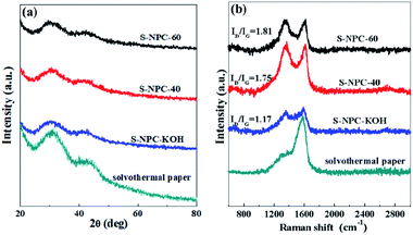 | ||
| Fig. 3 (a) XRD patterns, and (b) Raman spectra of solvothermal paper, S-NPC-KOH, S-NPC-40 and S-NPC-60. | ||
The porous texture of the as-prepared samples was investigated by the N2 adsorption/desorption measurements at 77 K. All the N2-adsorption curves (Fig. 4a) present a representative type I isotherm, which suggests that the samples have a microporous structure.24 With increase of the activation time, the N2-adsorption curves of S-NPC-60 display combined characteristics of type I/IV isotherms with a hysteresis loop (H2 type) at relative pressures ranging from 0.5 to 0.9, which indicates that the structure has macropores and mesopores. The pore size distributions of all the samples are shown in Fig. 4b. After activation the samples show structures with abundant pores, the major pore distribution peak of S-NPC-KOH is at 1–3 nm. For S-NPC-40 and S-NPC-60, due to the assisted activation effect of K2CO3, the pore size distribution plots show additional broad peaks at 3–10 nm, and with increase of the activation time, the broad peaks at 5–10 nm became obvious. The above results indicate that K2CO3 assisted KOH activation introduces abundant micropores and some meso- and macropores, which is in agreement with the observations from SEM and TEM images.
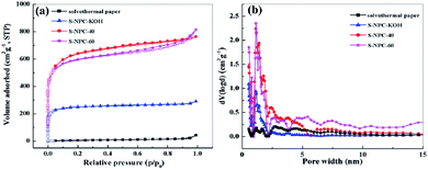 | ||
| Fig. 4 (a) Nitrogen adsorption–desorption isotherms and (b) pore size distribution of solvothermal paper, S-NPC-KOH, S-NPC-40 and S-NPC-60. | ||
The detailed information about the microstructure is summarized in Table 1. Brunauer–Emmett–Teller specific surface areas of the solvothermal paper, S-NPC-KOH, S-NPC-40 and S-NPC-60 samples are 21, 880, 2263, and 2104 m2 g−1, respectively. The S-NPC-40 sample exhibits the largest specific surface area and highest micropore ratio, which is beneficial to achieve high specific capacity and outstanding rate performance in LICs.
| Samples | Textural properties | ||||
|---|---|---|---|---|---|
| S BET (m2 g−1) | S micro (m2 g−1) | V total (cm3 g−1) | V micro (cm3 g−1) | V micro/Vtotal (%) | |
| Solvothermal paper | 21 | 0.00 | 0.067 | 0.00 | |
| S-NPC-KOH | 880 | 800 | 0.5 | 0.3 | 60 |
| S-NPC-40 | 2263 | 1876 | 1.2 | 0.8 | 67 |
| S-NPC-60 | 2104 | 1772 | 1.1 | 0.7 | 63 |
XPS was used to examine the surface chemical composition and types of elements present in solvothermal paper after activation. According to the XPS results (Fig. 5a), the S-NPC-40 sample shows four peaks at about 285, 531, 229, and 162 belonging to C 1s, O 1s, S 2s and S 2p. XPS data analysis (Table S1†) shows that the S and O atom content in S-NPC-40 is 2.1 and 9.0 at%, respectively. The sample without H2SO4 hydrothermal treatment shows a lower S content <1 at%, which indicates that the solvothermal treatment increased the S content of the raw materials. During the activation process, the sulfur functional groups were introduced into the carbon skeleton by in situ doping, thus the sulfur defects were formed.
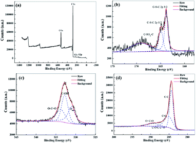 | ||
| Fig. 5 (a) XPS survey spectra of S-NPC-40, high-resolution (b) S 2p, (c) O 1s, and (d) C 1s XPS spectra of S-NPC-40. | ||
Fig. 5b depicts the high resolution XPS spectra of S 2p. It can be fitted into three peaks at binding energies of 163.9, 164.8, and 168.5 eV, which correspond to S 2p3/2, S 2p1/2, and the oxidized sulfur groups, respectively.27 The electrochemically active sulfur can enhance the capacity, and S functional groups can improve the electronic conductivity and wettability of carbon materials, both of which are positive effects for carbon-based electrode materials in LIC applications. Additionally, the high-resolution O 1s spectrum (Fig. 5c) of S-NPC-40 reveals the presence of three oxygen-based components, including O–C![[double bond, length as m-dash]](https://www.rsc.org/images/entities/char_e001.gif) O (∼532.8 eV), C–OH (∼532.7 eV), and surface adsorbed oxygen (∼530.9 eV).37Fig. 5d exhibits the high resolution spectra of C 1s. It can be divided into four peaks at around 284.3, 285.1, 287.4, and 289.3 eV, corresponding to C
O (∼532.8 eV), C–OH (∼532.7 eV), and surface adsorbed oxygen (∼530.9 eV).37Fig. 5d exhibits the high resolution spectra of C 1s. It can be divided into four peaks at around 284.3, 285.1, 287.4, and 289.3 eV, corresponding to C![[double bond, length as m-dash]](https://www.rsc.org/images/entities/char_e001.gif) C, C–O, C–O–C (or C
C, C–O, C–O–C (or C![[double bond, length as m-dash]](https://www.rsc.org/images/entities/char_e001.gif) O), and O–C
O), and O–C![[double bond, length as m-dash]](https://www.rsc.org/images/entities/char_e001.gif) O, respectively.38 The presence of oxygen defects could change the surface polarity of the electrode, promote the wettability of the electrode, and adjust the interlayer distance. The XPS results show that S, O and C atoms are covalently bonded. The synergy between S doping and O doping is beneficial to enhance the electrochemical performance of porous carbon. In addition, S-NPC-40 and S-NPC-60 show outstanding thermal stability (Fig. S1†), indicating that the carbon skeleton structure is preserved after doping.
O, respectively.38 The presence of oxygen defects could change the surface polarity of the electrode, promote the wettability of the electrode, and adjust the interlayer distance. The XPS results show that S, O and C atoms are covalently bonded. The synergy between S doping and O doping is beneficial to enhance the electrochemical performance of porous carbon. In addition, S-NPC-40 and S-NPC-60 show outstanding thermal stability (Fig. S1†), indicating that the carbon skeleton structure is preserved after doping.
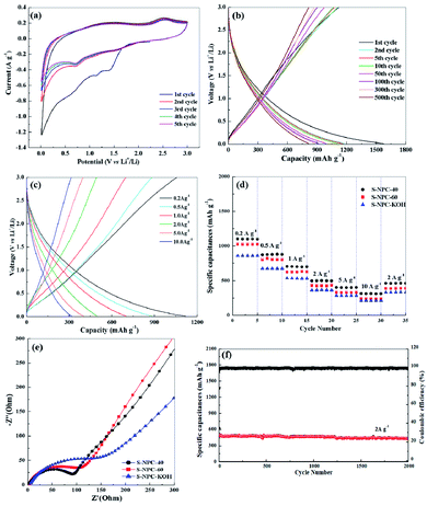
To investigate the electrochemical behavior of the S-NPC samples as both cathodic and anodic electrodes for LICs, coin-type half-cells were fabricated and tested. Fig. 6a shows the cyclic voltammetry (CV) curves for the initial five cycles of the S-NPC-40 anode at a scan rate of 0.1 mV s−1. The first cycle shows two broad reduction peaks at 0.4–1.0 V and 1.0–1.6 V, which correspond to the formation of solid-electrolyte interphase (SEI) film and the reactions of Li ion with functional groups at the heteroatom-doped carbon surface, respectively.25 The next four cycle curves maintain repeatable shapes, demonstrating the high reversibility of the lithiation–delithiation reaction and good stability of the SEI film.
Fig. 6b shows the charge/discharge curves of the S-NPC-40 anode at 0.1 A g−1. S-NPC-40 exhibits an initial discharge capacity of 1582 mA h g−1 and initial charge capacity of 1102 mA h g−1 with a coulombic efficiency of 69%. After the 500th cycle, a high specific capacity of approximately 817 mA h g−1 (higher than that of S-NPC-60 and S-NPC-KOH Fig. S2†) was attained, which proves the superior electrochemical cycling stability of the S-NPC-40 sample. Moreover, the S-NPC-40 electrode shows enhanced rate performance, with specific capacities of about 1117, 871, 704, 494, 407 and 302 mA h g−1 at 0.2, 0.5, 1.0, 2.0, 5.0 and 10 A g−1, respectively. Compared with S-NPC-KOH and S-NPC-60, the S-NPC-40 sample has the highest specific capacity at a current density of 0.2 to 10 A g−1. When the current density returned to 2.0 A g−1, the S-NPC-40 sample shows a specific capacity of 461 mA h g−1, which verifies that the net-like porous structure is essential for the good rate capability of the carbon material. Meanwhile, Fig. 6e compares the electrochemical impedance spectra (EIS) of the three samples as anodes. The S-NPC-40 sample has the smallest charge transfer resistance, suggesting that a fast and efficient faradaic redox reaction occurred at the electrode surface due to the 3D net-like porous structure. It is noted that the S-NPC-40 anode shows excellent cycle stability. A specific capacity of 440 mA h g−1 is still retained after 2000 cycles at a current density of 2 A g−1, as well as coulombic efficiency up to 97% (Fig. 6c and S3†). After cycling, the structure and morphology of S-NPC-40 are maintained (Fig. S4 and S5†), indicating that the amorphous net-like porous structure is beneficial to Li ion transmission.
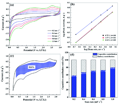
In order to explore the charge storage mechanisms of S-NPC, the CV curves of the S-NPC-40 sample at different scan rates were tested and analyzed. As shown in Fig. 7a, the CV shape is well maintained at the scan rate of 0.2 to 1.0 mV s−1; the two broad oxidation and reduction peaks correspond to the faradaic reactions from the Li ion intercalation, and the quasirectangular shape of the CV curves in the high potential region implies the non-faradaic reversible Li ion adsorption and pseudocapacitance.39 Based on the power law formula i = avb, where a and b are constants, if the b value is equal to 0.5 it indicates a diffusion-controlled process and if the b value is equal to 1 it indicates a capacitive contribution process.40,41 As shown in Fig. 7b, the plot obtained for the peak current shows a good linear relationship. The b value is calculated to be 0.88, 0.82 and 0.88 at 0.72, 1.57 and 2.54 V, respectively, suggesting fast kinetics dominated by the capacitive behavior. This capacitive contribution can be further quantitatively differentiated by the current separation method. The current at a fixed potential can be expressed as a combination of capacitive behavior (k1v) and diffusion controlled Li intercalation process (k2v1/2); the equation can be rewritten as i = k1v + k2v1/2.35,42 The capacitive contribution ratio of the S-NPC-40 anode at 0.2 mV s−1 is 58.8%, as shown in the shadowed area of the CV curve in Fig. 7c. Moreover, the capacitive contribution ratio increases with increasing scan rate, and it can be up to 79% at a scan rate of 1.0 mV s−1 (Fig. 7d), indicating a major capacitive-controlled process of the S-NPC-40 anode at high rates.
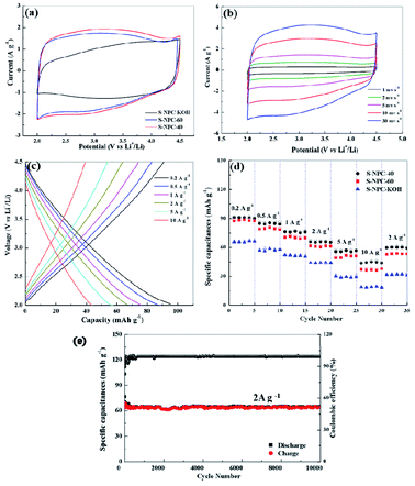
The cathode performance of S-NPC-40 was investigated between 2.0 and 4.5 V (vs. Li/Li+). The CV curves of the three samples recorded at 5 mV s−1 are shown in Fig. 8a. All CV curves of the S-NPC electrodes exhibit quasirectangular shapes with small humps, which suggest a combination effect of electrical double-layer capacitance (EDLC) and pseudo-capacitance.43 EDLC originates from anion (PF6−) adsorption/desorption in the pores and surface of porous carbon, and the pseudo-capacitance is caused by the interaction between the electrolyte and heteroatoms (S, O) of carbon materials. The CV curve area of the S-NPC-40 electrode is larger than that of S-NPC-KOH and S-NPC-60 indicating that the net-like hierarchical porous structure can effectively improve the capacitive behavior via more favorable ion diffusion channels of electrolyte ion adsorption/desorption. It is important to note that the CV curve of the S-NPC-40 cathode maintains a good rectangular shape even at a high scan rate of 30 mV s−1. The result indicates that S-NPC-40 exhibits outstanding rate performance, originating from its interconnected hierarchical porous network. Meanwhile, the charge and discharge curves of the S-NPC-40 cathode are recorded from 0.2 to 10.0 A g−1, as shown in Fig. 8c. S-NPC-40 displays specific capacitances of 95.9, 87.0, 76.0, 66.0, 56.1, and 43.2 mA h g−1 at 0.2, 0.5, 1.0, 2.0, 5.0 and 10.0 A g−1, respectively. Compared with S-NPC-KOH and S-NPC-60 samples, the S-NPC-40 electrode exhibited the highest rate specific capacitances at all current densities (Fig. 8d and S6†). Besides, after high rate tests, the specific capacitances of the S-NPC-40 cathode can still increase back to 60.0 mA h g−1 at 2 A g−1, higher than S-NPC-KOH (32.2 mA h g−1) and S-NPC-60 (53.2 mA h g−1). The cycle performance of the S-NPC-40 cathode is shown in Fig. 8e. After 10![[thin space (1/6-em)]](https://www.rsc.org/images/entities/char_2009.gif) 000 cycles at a current density of 2 A g−1, S-NPC-40 achieves a capacity retention rate of about 86%, and the net-like porous morphology is maintained (Fig. S5†), demonstrating that it is a promising cathodic material for high-performance LICs.
000 cycles at a current density of 2 A g−1, S-NPC-40 achieves a capacity retention rate of about 86%, and the net-like porous morphology is maintained (Fig. S5†), demonstrating that it is a promising cathodic material for high-performance LICs.
The outstanding electrochemical performance of S-NPC-40 samples as both cathode and anode can be ascribed to the 3D interconnected network and abundant S, O containing defects. Firstly, the large surface area with micropores can increase the electrolyte/electrode interface, enabling facile electrolyte penetration into the active material, resulting in large capacitance contribution. Secondly, the 3D interconnected porous network can shorten the charge diffusion distance and accelerate electron transfer. Thirdly, S doping expands carbon interlayer spacing, which facilitates diffusion of Li ions, improving the electrode kinetics. Finally, S, O doping can create more defects and improve the wettability of the surface, to enhance the electrochemical performance of porous carbon.
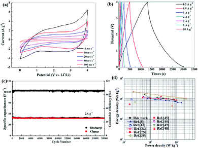
To evaluate the electrochemical performance of LICs with S-NPC electrodes, a full LIC was constructed using S-NPC-40 as the cathode, prelithiated S-NPC-40 as the anode, and 1 mol L−1 LiPF6 as the electrolyte. Generally, the charge-storage mechanism of LICs with two same porous carbon electrodes can be described as follows: during the charge process, the PF6− ions are absorbed in the pores and surface of the cathode through EDLC and pseudo-capacitance effect (the interaction between the S and O functional groups and electrolyte), while the Li ions are transferred to the anode via intercalation into the carbon layer or adsorbed on the surface of the anode. The discharge process is the reverse of the charge process.24 To balance the charge between the cathode and anode, the mass ratio of the cathode to anode was determined to be about 3. Fig. 9a shows the CV curves of the S-NPC-40//S-NPC-40 LIC at different scan rates from 5 to 100 mV s−1 at a potential rage of 0–4.0 V. All of the CV curves show a similar rectangular shape, indicating excellent capacitive behavior. Moreover, as the scan rate increases, the CV curve shape is maintained, revealing high reversibility and good rate capability. The charge and discharge curves of the S-NPC-40//S-NPC-40 LIC at different current densities show a nearly symmetrical triangle shape (Fig. 9b), indicating that the energy storage mechanism of S-NPC-40 is mainly controlled by the EDLC process. Based on the constant current charge/discharge curve calculation, the corresponding specific capacitance values (based on the total mass active materials of the two electrodes) are 79.3, 69.5, 65.7, 56, 53.3, 52.5, and 35.0 F g−1 at the current densities of 0.2, 0.5, 1, 2, 3, 5, and 10 A g−1, respectively. Furthermore, outstanding cycling stability was obtained with 82% capacity retention after 20![[thin space (1/6-em)]](https://www.rsc.org/images/entities/char_2009.gif) 000 cycles at a current density of 2 A g−1 as well as superior coulombic efficiency of almost 100% (Fig. 9c). As Fig. S7† shows, after cycling, the charge-transfer resistance of S-NPC-40 shows a small increase, which is attributed to the formation and growth of the SEI film. The different working windows and prolonged discharging time could be achieved by the series–parallel connection of LICs (Fig. S8†). Ragone plot of the S-NPC-40//S-NPC-40 LIC device is shown in Fig. 9d. The S-NPC-40//S-NPC-40 LIC delivers a high energy density of 176.1 W h kg−1 at a power density of 400 W kg−1. Even at a high power density of 20 kW kg−1, S-NPC-40//S-NPC-40 LIC can still deliver a high energy density of 77.8 W h kg−1. Detailed comparisons of the energy and power densities with some reported LICs, such as NDPC-0.5//NDPC-0.5 LIC,25 PANi@CNF-10//CNF LIC,5 NCNs-2//NCNs-2 LICs,35 BNC//BNC LIC,24 a-EW-NaCl//Fe3O4@C,44 Nb2O5//AC,12 AC//M-LTO,45 Li3VO4//AC,46 Ti3C2Tx/CNT//AC,47, and PGCs//AC,48 manifest the promising performance of the S-NPC-40//S-NPC-40 LIC. These results demonstrate that the S-NPC-40//S-NPC-40 LIC can act as a promising device in practical applications.
000 cycles at a current density of 2 A g−1 as well as superior coulombic efficiency of almost 100% (Fig. 9c). As Fig. S7† shows, after cycling, the charge-transfer resistance of S-NPC-40 shows a small increase, which is attributed to the formation and growth of the SEI film. The different working windows and prolonged discharging time could be achieved by the series–parallel connection of LICs (Fig. S8†). Ragone plot of the S-NPC-40//S-NPC-40 LIC device is shown in Fig. 9d. The S-NPC-40//S-NPC-40 LIC delivers a high energy density of 176.1 W h kg−1 at a power density of 400 W kg−1. Even at a high power density of 20 kW kg−1, S-NPC-40//S-NPC-40 LIC can still deliver a high energy density of 77.8 W h kg−1. Detailed comparisons of the energy and power densities with some reported LICs, such as NDPC-0.5//NDPC-0.5 LIC,25 PANi@CNF-10//CNF LIC,5 NCNs-2//NCNs-2 LICs,35 BNC//BNC LIC,24 a-EW-NaCl//Fe3O4@C,44 Nb2O5//AC,12 AC//M-LTO,45 Li3VO4//AC,46 Ti3C2Tx/CNT//AC,47, and PGCs//AC,48 manifest the promising performance of the S-NPC-40//S-NPC-40 LIC. These results demonstrate that the S-NPC-40//S-NPC-40 LIC can act as a promising device in practical applications.
Conclusions
In summary, S and O dual-doped net-like porous carbon derived from waste paper has been successfully prepared through solvothermal treatment and high temperature activation. It demonstrates that S and O dual doping results in expanded interlayer distance, improved charge-storage active sites, and enhanced electrical conductivity of the porous carbon networks. Under optimized activation conditions (K2CO3 assisted KOH activation), the obtained S-NPC-40 electrodes show high surface area, 3D net-like hierarchical porous structure and high S/O contents (2.0 at% for S, and 9.0 at% for O). Because the 3D network porous structure reduces the channels for ion transport, as well as S, O doping induces more-capacitive charge-storage contributions for both anode and cathode, S-NPC-40 electrodes exhibit high specific capacity, rate performance and excellent cycle stability as both cathode material and anode material for LICs. Benefiting from the efficient circumvention of electrochemical discrepancies between Li+ storage anode and PF6− adsorption cathode, the S-NPC-40//S-NPC-40 LIC presents a high energy density of 176.1 W h kg−1 at a power density of 400 W kg−1, as well as superior cycling stability with 82% capacitance retention after 20![[thin space (1/6-em)]](https://www.rsc.org/images/entities/char_2009.gif) 000 cycles. This study provides a new opportunity to the design of porous carbon electrodes for practical application in LICs and gives a novel technology perspective for recycling of waste paper.
000 cycles. This study provides a new opportunity to the design of porous carbon electrodes for practical application in LICs and gives a novel technology perspective for recycling of waste paper.
Conflicts of interest
There are no conflicts to declare.Acknowledgements
The authors thank the Natural Science Foundation of Ningxia Province (No. 2018AAC03022), the Key Research and Development Program of Ningxia Province of China (No. 2018BEE03012), and the National First-rate Discipline Construction Project of Ningxia (Chemical Engineering & Technology, NXYLXK2017A04).Notes and references
- J. R. Miller and P. Simon, Science, 2008, 321, 651–652 CrossRef CAS
.
- W. H. Niu and Y. Yang, ACS Energy Lett., 2018, 3, 2796–2815 CrossRef CAS
.
- S. X. Yan, Q. Wang, S. H. Luo, Y. H. Zhang, X. Liu, Y. G. Liu, Z. Y. Wang, A. M. Hao and T. F. Yi, J. Power Sources, 2020, 461, 228151 CrossRef CAS
.
- B. Li, J. S. Zheng, H. Y. Zhang, L. M. Jin, D. J. Yang, H. Lv, C. Shen, A. Shellikeri, Y. R. Zheng, R. Q. Gong, J. P. Zheng and C. M. Zhang, Adv. Mater., 2018, 30, 1705670 CrossRef
.
- C. P. Han, J. Tong, X. Tang, D. Zhou, H. Duan, B. H. Li and G. X. Wang, ACS Appl. Mater. Interfaces, 2020, 12, 10479–10489 CrossRef
.
- Y. F. Ma, H. C. Chang, M. Zhang and Y. S. Chen, Adv. Mater., 2015, 27, 5296–5308 CrossRef CAS
.
- H. Kim, M. Y. Cho, M. H. Kim, K. Y. Park, H. Gwon, Y. Lee, K. C. Roh and K. Kang, Adv. Energy Mater., 2013, 3, 1500–1506 CrossRef CAS
.
- H. W. Wang, C. R. Zhu, D. L. Chao, Q. Y. Yan and H. J. Fan, Adv. Mater., 2017, 29, 1702093 CrossRef
.
- H. J. Huang, X. Wang, E. Tervoort, G. B. Zeng, T. Liu, X. Chen, A. Sologubenko and M. Niederberger, ACS Nano, 2018, 12, 2753–2763 CrossRef CAS
.
- G. K. Wang, C. X. Lu, X. Zhang, B. A. Wan, H. Y. Liu, M. R. Xia, H. Y. Gou, G. Q. Xin, J. Lian and Y. G. Zhang, Nano Energy, 2017, 36, 46–57 CrossRef CAS
.
- G. Tang, L. J. Cao, P. Xiao, Y. H. Zhang and H. Liu, J. Power Sources, 2017, 355, 1–7 CrossRef CAS
.
- B. H. Deng, T. Y. Lei, W. H. Zhu, L. Xiao and J. P. Liu, Adv. Funct. Mater., 2018, 28, 1704330 CrossRef
.
- E. Kim, H. Kim, B. J. Park, Y. H. Han, J. H. Park, J. Cho, S. S. Lee and J. G. Son, Small, 2018, 14, 1704209 CrossRef
.
- L. Z. Sheng, L. L. Jiang, T. Wei and Z. J. Fan, Small, 2016, 12, 5217–5227 CrossRef CAS
.
- J. H. Won, H. M. Jeong and J. K. Kang, Adv. Energy Mater., 2017, 7, 1601355 CrossRef
.
- B. Li, F. Dai, Q. F. Xiao, L. Yang, J. M. Shen, C. M. Zhang and M. Cai, Energy Environ. Sci., 2016, 9, 102–106 RSC
.
- Y. Yang, Nanoscale, 2020, 12, 3560–3573 RSC
.
- F. B. Fu, D. J. Yang, W. L. Zhang, H. Wang and X. Q. Qiu, Chem. Eng. J., 2020, 392, 123721 CrossRef CAS
.
- Y. W. Zheng, W. Zhao, D. D. Jia, Y. Liu, L. Cui, D. Wei, R. K. Zheng and J. Q. Liu, Chem. Eng. J., 2020, 387, 124161 CrossRef CAS
.
- H. L. Wang, D. Mitlin, J. Ding, Z. Li and K. Cui, J. Mater. Chem. A, 2016, 4, 5149–5158 RSC
.
- W. T. Feng, Y. P. Cui, W. Liu, H. L. Wang, Y. Zhang, Y. X. Du, S. Liu, H. L. Wang, X. Gao and T. Q. Wang, ACS Nano, 2020, 14, 4938–4949 CrossRef CAS
.
- H. T. Sun, L. Mei, J. F. Liang, Z. P. Zhao, C. Lee, H. L. Fei, M. N. Ding, J. Lau, M. F. Li, C. Wang, X. Xu, G. L. Hao, B. Papandrea, I. Shakir, B. Dunn, Y. Huang and X. F. Duan, Science, 2017, 356, 599–604 CrossRef CAS
.
- T. F. Zhang, F. Zhang, L. Zhang, Y. H. Lu, Y. Zhang, X. Yang, Y. F. Ma and Y. Huang, Carbon, 2015, 92, 106–118 CrossRef CAS
.
- Q. Y. Xia, H. Yang, M. Wang, M. Yang, Q. B. Guo, L. M. Wan, H. Xia and Y. Yu, Adv. Energy Mater., 2017, 7, 1701336 CrossRef
.
- K. X. Zou, Z. X. Guan, Y. F. Deng and G. H. Chen, Carbon, 2020, 161, 25–35 CrossRef CAS
.
- F. Sun, X. Y. Liu, H. B. Wu, L. J. Wang, J. H. Gao, H. X. Li and Y. F. Lu, Nano Lett., 2018, 18, 3368–3376 CrossRef CAS
.
- B. Quan, A. Jin, S. H. Yu, S. M. Kong, J. Jeong, H. D. Abruna, L. Y. Jin, Y. Piao and Y. E. Sung, Adv. Sci., 2018, 5, 1700880 CrossRef
.
- L. Chen, C. Lian, H. Jiang, L. X. Chen, J. Yan, H. L. Liu and C. Z. Li, Chem. Eng. Sci., 2020, 217, 115496 CrossRef CAS
.
- D. Puthusseri, V. Aravindan, B. Anothumakkool, S. Kurungot, S. Madhavi and S. Ogale, Small, 2014, 10, 4395–4402 CAS
.
- X. L. Yu, C. Z. Zhan, R. T. Lv, Y. Bai, Y. X. Lin, Z. H. Huang, W. C. Shen, X. P. Qiu and F. Y. Kang, Nano Energy, 2015, 15, 43–53 CrossRef CAS
.
- S. Ding and Y. X. Liu, Fuel, 2020, 260, 116382 CrossRef CAS
.
- Y. H. Sun, J. H. Zhao, J. L. Wang, N. Tang, R. J. Zhao, D. D. Zhang, T. T. Guan and K. X. Li, J. Phys. Chem. C, 2017, 121, 10000–10009 CrossRef CAS
.
- B. Wang, J. H. Qiu, H. Feng, E. Sakai and T. Komiyama, Electrochim. Acta, 2016, 190, 229–239 CrossRef CAS
.
- C. J. Cui, W. Z. Qian, Y. T. Yu, C. Y. Kong, B. Yu, L. Xiang and F. Wei, J. Am. Chem. Soc., 2014, 136, 2256–2259 CrossRef CAS
.
- Z. Li, L. J. Cao, W. Chen, Z. C. Huang and H. Liu, Small, 2019, 15, 1805173 CrossRef
.
- X. J. Chen, X. M. Deng, N. Y. Kim, Y. Wang, Y. Huang, L. Peng, M. Huang, X. Zhang, X. Chen, D. Luo, B. Wang, X. Z. Wu, Y. F. Ma, Z. Lee and R. S. Ruoff, Carbon, 2018, 132, 294–303 CrossRef CAS
.
- S. Z. Wang, H. Y. Liu and J. L. Wang, J. Hazard. Mater., 2020, 387, 121669 CrossRef CAS
.
- Z. Ling, Z. Y. Wang, M. D. Zhang, C. Yu, G. Wang, Y. F. Dong, S. H. Liu, Y. W. Wang and J. S. Qiu, Adv. Funct. Mater., 2016, 26, 111–119 CrossRef CAS
.
- M. Y. Liu, Z. P. Zhang, M. L. Dou, Z. L. Li and F. Wang, Carbon, 2019, 151, 28–35 CrossRef CAS
.
- Y. P. Cui, W. Liu, Y. Lyu, Y. Zhang, H. L. Wang, Y. J. Liu and D. Li, J. Mater. Chem. A, 2018, 6, 18276–18285 RSC
.
- W. X. Yang, J. H. Zhou, S. Wang, W. Y. Zhang, Z. C. Wang, F. Lv, K. Wang, Q. Sun and S. J. Guo, Energy Environ. Sci., 2019, 12, 1605–1612 RSC
.
- B. H. Shan, Y. P. Cui, W. Liu, Y. Zhang, S. Liu, H. L. Wang, L. J. Sun, Z. P. Wang and R. T. Wu, ACS Sustainable Chem. Eng., 2018, 6, 14989–15000 CrossRef CAS
.
- N. Wang, C. Z. Wang, L. X. He, Y. Wang, W. C. Hu and S. Komarneni, Electrochim. Acta, 2019, 298, 717–725 CrossRef CAS
.
- R. Y. Shi, C. P. Han, H. F. Li, L. Xu, T. F. Zhang, J. Q. Li, Z. Q. Lin, C. P. Wong, F. Y. Kang and B. H. Li, J. Mater. Chem. A, 2018, 6, 17057–17066 RSC
.
- D. B. Ruan, M. S. Kim, B. Yang, J. Qin, K. B. Kim, S. H. Lee, Q. X. Liu, L. Tan and Z. J. Qiao, J. Power Sources, 2017, 366, 200–206 CrossRef CAS
.
- L. F. Shen, H. F. Lv, S. Q. Chen, P. Kopold, P. A. van Aken, X. J. Wu, J. Maier and Y. Yu, Adv. Mater., 2017, 29, 1700142 CrossRef
.
- P. Yu, G. J. Cao, S. Yi, X. Zhang, C. Li, X. Z. Sun, K. Wang and Y. W. Ma, Nanoscale, 2018, 10, 5906–5913 RSC
.
- G. C. Li, Z. L. Yin, H. J. Guo, Z. X. Wang, G. C. Yan, Z. W. Yang, Y. Liu, X. B. Ji and J. X. Wang, Adv. Energy Mater., 2019, 9, 1700142 Search PubMed
.
Footnote |
| † Electronic supplementary information (ESI) available: XPS data, TGA results, XRD patterns of S-NPC-40 samples before and after cycling, SEM image of the S-NPC-40 anode and cathode after cycling, charge–discharge curves of the S-NPC-60 and S-NPC-KOH anodes at different current densities, cycle performance of the S-NPC-40 anode at a current density of 0.2 A g−1, charge–discharge curves of the S-NPC-60 and S-NPC-KOH cathodes at different current densities, Nyquist plots of S-NPC-40 before and after cycling, and the GCD curves of devices connected in series and parallel. See DOI: 10.1039/d0na00824a |
| This journal is © The Royal Society of Chemistry 2021 |

