 Open Access Article
Broadband asymmetric light transmission interfaces for luminescent solar concentrators
Vincent
Oliveto
and
Diana-Andra
Borca-Tasciuc
 *
*
Mechanical, Aerospace and Nuclear Engineering Department, Rensselaer Polytechnic Institute, Troy, NY, USA. E-mail: borcad@rpi.edu
First published on 3rd May 2021
Abstract
Luminescent solar concentrators (LSCs) are actively researched to be incorporated into multi-functional building envelope systems. They consist of a plastic matrix with absorbing–emitting media, which guides and concentrates light to edges where solar cells are located. A main drawback of LSCs is escape cone losses at the surface intercepting light. This study investigates trapezoidal nanostructures for creating an interface that enables asymmetric light transmission and reduces these losses. The study employs alumina nanostructures on a PMMA substrate, materials of relevance to LSC applications. The geometry of nanostructures was optimized to maximize asymmetry in the 700–1100 nm wavelength interval, which corresponds to the range best utilized by silicon solar cells. The multiphysics software COMSOL was utilized to simulate forward (air to PMMA) and backward (PMMA to air) transmission. Spectral transmissivity was calculated for this wavelength interval for a variety of incident polar and azimuthal angles. The largest difference between forward and backward light transmission was found at 720 nm, as designed. The forward spectral transmissivity for all polar angles considered was found to be approximately 77% in the 700–1100 nm range at an azimuth angle of zero. The backward spectral directional transmissivity in this range was approximately 37%, resulting in a 40% difference. The difference for the entire wavelength range of 400–1200 nm was approximately 37%. Similar results were obtained when the azimuth angle was varied. All these show that the incorporation of nanostructured interfaces can effectively reduce optical losses in LSCs, which will help increase their efficiency. This will make LSCs a more viable solution for use in zero or net-zero energy buildings.
1. Introduction
Over 80% of available energy is used in cities and a significant portion of this energy is used in buildings.1 There is a relatively recent recognition that building energy expenditure contributes towards the greenhouse effect and climate change in a non-negligible manner. Therefore, countries around the world are enacting legislation requiring net-zero or near zero energy buildings.2 Meeting such requirements oftentimes necessitates on-site energy production. While solar power generation is the approach to go in such circumstances, due to the high population density and the complex architecture of urban environments, it is exceedingly difficult to plan and implement traditional solar installations. One of the solutions currently explored to address this situation is luminescent solar concentrators (LSC), which can be integrated seamlessly into the building envelope.3,4 Although first proposed in the 70's, research in LSCs is now undergoing a revival due to their potential applications as building integrated sustainable energy technologies. The market for these concentrators is expected to boom as soon as 2023 and they are particularly exciting because they allow for a seamless architectural integration of solar power harvesting technologies within the building envelope.5–7LSCs work by concentrating large areas of sunlight to smaller solar cells imbedded on the sides. LSCs are made of a transparent glass or plastic sheet that contains luminescent species (organic dyes, quantum dots, and fluorophores), which can be either uniformly distributed throughout the matrix or concentrated at the bottom of the LSC. These luminescent species have a specific absorption range and an emission range. Their purpose is to absorb light within a certain wavelength region and to emit it at a slightly lower energy level. The role of the reemission is double folded. It helps the light to travel at more extreme angles enabling an increase in total internal reflection (TIR), which enables the glass or plastic matrix to act as a waveguide. The light is focused toward the edge, where the solar cell is located. In addition, the luminescent species also red-shift the light, towards the spectral range that is more efficiently converted by the solar cell.
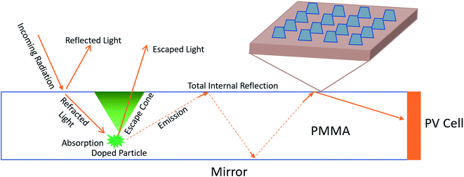
The main impediment to LSC applications has been their very low efficiency. This is primarily due to light leaving the device through the top surface via escape cone losses. Light is able to escape through the top surface if the incident angle falls below the “critical angle” which can be determined using the indices of refraction of the two media. The escape cone is illustrated below in Fig. 1. In fact, up to 40–50% of all light that was absorbed by luminophores is lost through the escape cone, which correlates to a 50–70% loss of photons.3,8 Most attempts to correct this problem focus on spectrally selective mirrors, Bragg reflectors, organic mirrors, photonic structures, and “resonance shifting” bicavity layers.9–13 They all operate under a similar premise, and they are simply constructed through different means. While effective, their main weakness is the narrow operating range. For example, spectrally selective mirrors are highly reflective in the “emission range” and highly transmissive in the “absorption range” of the LSC. The emission range is typically less than 200 nm, which means losses at other wavelengths are unaffected by the solution implemented by adding mirrors.
An alternative approach to these would be a broadband solution that allows all wavelengths to enter, but also blocks them from leaving the LSC. This concept of asymmetric light transmission is known as the Woods-Rayleigh anomaly, and was first discovered and quantified in the early 20th century.14,15 More recently, this effect was investigated numerically for a number of nanostructured interfaces.16–20 A recent study, relevant to the study discussed in this paper, is by Ozer et al.18 who showed asymmetric light transmission for normal incidence through an interface between air and periodic trapezoidal aluminum nanostructures on a lossless sapphire substrate.
The objective of this paper is to examine similar interfaces with trapezoidal nanostructures as shown in Fig. 1, implemented with materials of relevance to intended applications and realistic properties, and explore the directional dependence of forward (from air towards the interface) and backward (from the substrate towards the interface) transmission. These proposed nanostructures would coat the top surface of the LSC to reduce escape cone losses from within the waveguide, as seen in Fig. 1. This study is accomplished via numerical simulation carried out in the COMSOL wave optics module.
2. Simulation setup
The materials utilized in this study are polymethylmethacrylate (PMMA) as the substrate with aluminum oxide nanostructures. PMMA was chosen because it is used in LSCs,21–23 it is already commonly found in buildings and constructions, and it is easy to manufacture/buy. Aluminum oxide was chosen for similar reasons. Furthermore, alumina nanostructures could potentially be obtained through large scale anodization techniques, a key aspect of the cost sensitive building industry.24 The properties of the selected materials were based on the COMSOL material library. The PMMA is from the study of Beadie et al.25 The alumina is from Malitson and Dodge.26 Both are experimental datasets pre-loaded into the COMSOL's wave optics module. The effects of luminescent species light transmission were neglected as most LSCs have relatively low luminescent species concentrations or the fluorophores are located away from the air/matrix interface.To proceed with this study, the optimum periodicity of the nanostructures that would lead to asymmetric transmission at the wavelength of interest was determined. This was done by predicting the wavelengths for which all diffraction orders will be able to propagate in the “forward” direction, but only the zeroth diffraction order will be able to propagate in the “backward” direction with eqn (1):14,15
λ = pn(1 + sin![[thin space (1/6-em)]](https://www.rsc.org/images/entities/char_2009.gif) θ) θ) | (1) |
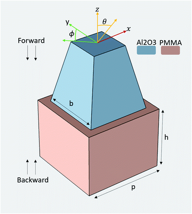
In eqn (1)λ is the wavelength, p is the periodicity of the nanostructures (Fig. 2), and n is the refractive index of the material that light enters. By using this equation and knowing the average index of refraction for the LSC substrate, an effective range for p was calculated. For this study, the focus was on preventing the escape of the wavelength in the interval between 700 and 1000 nm, which corresponds to wavelengths best utilized by silicon solar cells.27
While eqn (1) was initially used to determinate the range for p, the final results presented in this study were obtained by performing a parameter sweep for both the periodicity and geometry of the trapezoidal pyramid, including the height, h, base side, b and aspect ratio. The aspect ratio is the ratio of the side of the top surface of the pyramid to the side of the bottom surface of the pyramid. In all these studies, the height of the substrate was kept the same as that of the pyramid.
In a typical simulation run, in setting up the model, a “box” of air was placed on top of the PMMA substrate with a height of 3h so that light could propagate downwards through a real medium. Floquet periodic conditions were applied on all lateral sides.28 They allow the user to select the directions that a model will repeat. COMSOL was set to automatically calculate the number of diffraction orders for this set up. A port boundary was added on the top surface of the air box and a second port boundary was placed on the bottom surface of the PMMA. Port boundaries will control the propagation and collection of light for transmission and reflection calculations. For the forward direction, the upper port had wave excitation turned on with a power of 1 W and 1 V m−1 electric field propagating in the x direction. The lower port had the same settings except that the wave excitation was turned off. To study light propagation in the backward direction the ports settings were vice versa. The mesh used was a predefined “finer” mesh for all geometric components. A brief mesh analysis showed that a smaller mesh then produced approximately 3% variation in results. In addition, prior to performing the studies presented in this work, we benchmarked our simulation procedure using the results presented in ref. 19. The procedure was also checked by comparing PMMA–air interface results with published transmissivity data for forward and backward propagation directions.29
For a given set of parameters (p, h, b, and aspect ratio) a wavelength domain study within a range of wavelengths from 400–1200 nm at 20 nm incremental steps was completed in COMSOL. All parametric studies were performed at normal incidence. For the set of parameters that gave optimum transmission at normal incidence, further studies were performed to understand the change in transmission with the direction of incoming light.
3. Results
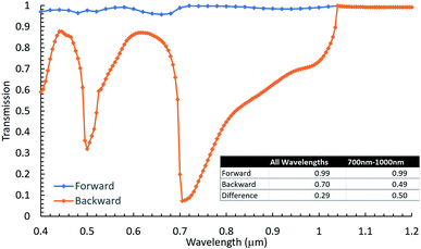
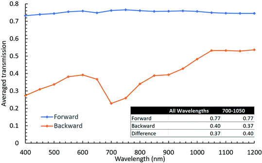
One of the most promising interface configurations was found for p = 700 nm, b = 550 nm, h = 550 nm and an aspect ratio of the top side of the pyramid to its bottom side of 0.55. For this configuration, the calculated forward and backward spectral transmissivity at normal incidence is shown in Fig. 3 as a function of wavelength. The inset table in Fig. 3 shows the transmission for all wavelengths for normal incidence along with the difference between backward and forward transmission. The total transmission shown in table 1 was determined by first summing the transmission over all wavelengths. This was done by using the trapezoidal rule to find the average area under the curve as shown in eqn (2): | (2) |
 | (3) |
As shown by Fig. 3, this interface exhibits asymmetric light transmission within the full range of 400 nm to 1200 nm and is particularly effective in the range of 700–1000 nm, based on which the periodicity was initially determined. For example, at 720 nm (selected because it is a local minimum that could be compared to the data collected in the forward transmission simulation, which was sampled at a larger wavelength increment) the difference between forward and backward transmission reaches approximately 90%, while the average difference in 700–1000 nm is approximately 50%.
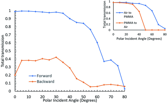
While this configuration was selected as being one of the winners based on normal incidence data, in the intended application, understanding transmission dependence on the angle of incidence is critical as the sun position changes continuously through the day and seasons. Thus, the effect of the polar and azimuthal angles of incidence (Fig. 2) was investigated next. The effect of the polar angle was first explored at 720 nm keeping the azimuth angle as 0°. For this purpose, the simulation was set as described above, but a parametric sweep study was added to run cases of incident polar angles starting from 0° and increasing incrementally by 5° to a final position of 80°.
The results are shown in Fig. 4 along with results from a similar simulation of a plain air/PMMA interface, which were found to agree well with literature data.29 As can be seen in this figure, asymmetric light transmission continues to occur over all incident angles. The trend observed for forward transmission as a function of polar angle is very similar to that observed for the PMMA/air interface shown in the inset of Fig. 4. Specifically, the total transmission decreases while the polar incident angle increases. However, backward transmission is mostly suppressed at this wavelength, approaching zero after 50°, as also seen at the PMMA/air interface where transmission is cut to zero at this angle due to total internal reflection. Since alumina covers much of the upper surface area and has a higher index of refraction than PMMA, there is no total internal reflection that can take place, according to Snell's law.30 This is why a hard cutoff for transmission is not applicable to the nanostructured interface. Despite this, the difference between forward and backward transmission is greater with the nanostructure due to the asymmetric light transmission phenomenon.
The study shown in Fig. 4 was repeated for all wavelengths in the 400–1200 nm interval. At each simulated wavelength, the directionally averaged transmission (averaged over all θ studied at a specific wavelength) in both the forward and backward directions was calculated and is plotted in Fig. 5. The inset table in this figure shows the total averaged transmission, which represents the total over the entire wavelength interval for directionally averaged transmission shown in Fig. 5. Eqn (2) and (3) were used for these calculations, with the difference that t, in this case, is the directionally averaged transmission at a given wavelength, and in these equations λ is replaced with θ. As can be seen in Fig. 5, this interface effectively induces asymmetric light transmission given the simulation setup described that uses realistic materials, and tests across various incident angles within this 800 nm wavelength range. At λ = 700 nm, there is just over a 53% difference in averaged transmission, while the total averaged transmission difference is 37% for the entire wavelength range. For comparison, a baseline model was also created. This baseline model was made exactly the same, except that the repeating nanostructure was removed from the interface, leaving only the air and the PMMA substrate. The same simulations were preformed over all wavelengths and incident angles. These results showed that the model with the nanostructures outperformed the baseline by an average of 10% and peaked at 30% around 700 nm.
The final study performed was to investigate the effect of the azimuth angle. For this study, the transmission was calculated as a function of azimuthal angle of the propagating light for several different polar angles. Due to the symmetric design of our structure, it is only necessary to investigate the azimuth angle from 0° to 90°. However, the simulations were done varying the azimuth angle up to 180°, in 10° steps, in order to observe the effect of symmetry. This was done for a variety of polar angles, between 0 and 80°, to determine the overall effect that the azimuthal angle will have at a particular wavelength. Not all the polar angles simulated are shown here to avoid an overcrowded graph. The three polar incident angles of 30°, 45°, and 60° were selected for illustration, because these angles cover the range where transmission starts to drop as seen in Fig. 4. The results for this are shown in Fig. 6. The effect of the azimuth angle is illustrated at 720 nm, the wavelength at which the difference between forward and backward transmission is close to the maximum.
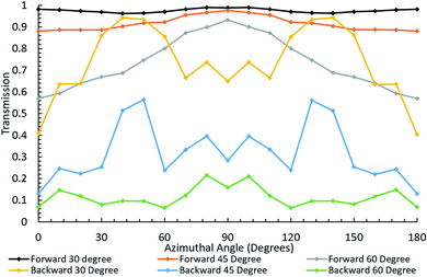 | ||
| Fig. 6 Transmission as a function of azimuthal angle for several polar angles at 720 nm. Each dot represents the simulation result, while the line connecting the dots is added for the visual purpose. | ||
As can be seen in Fig. 6, asymmetric light transmission continues to hold across all combinations of polar and azimuthal angles. The transmission averaged across all azimuthal angles and all polar angles considered was also calculated. This was done for the full range of the azimuth angles simulated for each of the six polar angles investigated (0, 15, 30, 45, 60, and 70). The total forward directional transmission was found to be around 86%, which is approximately 10% higher than the averaged forward transmission found from Fig. 4 at this wavelength.
Similarly, the backward transmission was found to be about 32%, which is again about 10% higher than the value found from Fig. 4. However, the difference between the forward and the backward transmission for all azimuth angles across all polar angles investigated was approximately 53%. The averaged transmission difference for the polar incident angle study shown in Fig. 5 is also approximately 53%. While the azimuthal angle does vary the results slightly, the overall trend and average transmission difference remains virtually the same. Multiple wavelengths were tested for these polar and azimuthal angles and they all yielded similar results.
4. Conclusion
In summary, a nanostructured surface was investigated for reducing optical losses in luminescent solar concentrators. This nanostructure was geometrically designed to be optimal for a wavelength range relevant to a silicon solar cell response. The interface studied was based on common materials used in the intended application. The results presented in this paper suggest that is possible to create interfaces with broadband asymmetric light transmission which operate over a wide range of polar and azimuthal incidence angles. While spectrally selective mirrors and other similar solutions may be more effective than 50%, they are only effective within a very small bandgap. The solution proposed here is the only wide bandgap solution that allows light to enter across an 800 nm wavelength range, while simultaneously permitting less than 45% of that light from leaving within the wavelength interval of 700–1000 nm averaged over all directions investigated. Such nanostructured interface materials are envisioned to enable more commercially viable incorporation of LSC technology into building integrated photovoltaics, ultimately leading to a more sustainable urban environment.Conflicts of interest
There are no conflicts to declare.Acknowledgements
V. O. acknowledges the DoD SMART scholarship for funding. The DoD had no role in the study design, data collection and analysis, decision to publish, or preparation of this manuscript. The authors would also like to thank Mr Duncan Smith for giving us access to COMSOL to run these simulations.References
- G. Lobaccaro and F. Frontini, Solar Energy in Urban Environment: How Urban Densification Affects Existing Buildings, Energy Procedia, 2014, 48, 1559–1569 CrossRef.
- M. Darby and I. Gerretsen, Which countries have a net zero carbon goal?, Climate Home News, 2019, vol. 14, https://www.climatechangenews.com/2019/06/14/countries-net-zero-climate-goal/ Search PubMed.
- M. D. Hughes, D.-A. Borca-Tasciuc and D. A. Kaminski, “Highly efficient luminescent solar concentrators employing commercially available luminescent phosphors,”, Sol. Energy Mater. Sol. Cells, 2017, 171, 293–301 CrossRef CAS.
- M. D. Hughes, D. E. Smith and D.-A. Borca-Tasciuc, Performance of wedge-shaped luminescent solar concentrators employing phosphor films and annual energy estimation case studies, Renewable Energy, 2020, 160, 513–525 CrossRef.
- F. Meinardi, F. Bruni and S. Brovelli, Luminescent solar concentrators for building-integrated photovoltaics, Nat. Rev. Mater., 2017, 2, 17072 CrossRef CAS.
- A. Ghosh, “Potential of building integrated and attached/applied photovoltaic (BIPV/BAPV) for adaptive less energy-hungry building's skin: A comprehensive review, J. Cleaner Prod., 2020, 123343 CrossRef.
- J. Roncali, Luminescent Solar Collectors: Quo Vadis?, Adv. Energy Mater., 2020, 10(36), 2001907 CrossRef CAS.
- M. G. Debije, P. P. C. Verbunt, B. C. Rowan, B. S. Richards and T. L. Hoeks, Measured surface loss from luminescent solar concentrator waveguides, Appl. Opt., 2008, 47(36), 6763 CrossRef CAS PubMed.
- R. Connell, C. Pinnell and V. E. Ferry, Designing spectrally-selective mirrors for use in luminescent solar concentrators, J. Opt., 2018, 20(2), 024009 CrossRef.
- I. M. Peters, J. C. Goldschmidt, P. Löper, L. Prönneke, B. Bläsi and A. Gombert, Design of photonic structures for the enhancement of the light guiding efficiency of fluorescent concentrators, Proceedings Volume 7002, Photonics for Solar Energy Systems II, 2008, 70020V–1, DOI:10.1117/12.781087.
- P. Verbunt, et al., Increased efficiency of luminescent solar concentrators after application of organic wavelength selective mirrors, Opt. Express, 2012, 20(suppl 5), A655–A668 CrossRef CAS PubMed.
- L. Slooff, A. Burgers and M. Debije, Reduction of escape cone losses in luminescent solar concentrators with cholosteric mirrors, Proc. SPIE, 2008, 7043, 704306 CrossRef.
- N. C. Giebink, G. P. Wiederrecht and M. R. Wasielewski, Resonance-shifting to circumvent reabsorption loss in luminescent solar concentrators, Nat. Photonics, 2011, 5(11), 694–701 CrossRef CAS.
- R. W. Wood, On a Remarkable Case of Uneven Distribution of Light in a Diffraction Grating Spectrum, Proc. Phys. Soc., London, 1902, 18(1), 269–275 CrossRef.
- L. Rayleigh, On the dynamical theory of gratings, Proc. R. Soc. London, Ser. A, 1907, 79, 399–416 Search PubMed.
- H. Zhu, F. Li, B. Tang, X. Zang and C. Jiang, Asymmetric transmission through metallic grating with dielectric substrate, Opt. Commun., 2014, 318, 41–46 CrossRef CAS.
- H. Rahal and F. AbdelMalek, “Asymmetric transport of light in arrow-shape photonic crystal waveguides, Superlattices Microstruct., 2017, 103, 358–364 CrossRef CAS.
- A. Ozer, H. Kocer and H. Kurt, Broadband and polarization-independent asymmetric transmission of visible light through a three-dimensional trapezoidal metallic metasurface, J. Opt. Soc. Am. B, 2018, 35(9), 2111–2117 CrossRef CAS.
- B. Tang, Z. Li, Z. Liu, F. Callewaert and K. Aydin, Broadband asymmetric light transmission through tapered metallic gratings at visible frequencies, Sci. Rep., 2016, 6, 39166 CrossRef CAS PubMed.
- A. Ozer, N. Yilmaz, F. T. Bagci, H. Kocer and H. Kurt, Tunable and asymmetric transmission of light in visible spectrum, Metamaterials, 2019, 11025, 110250G Search PubMed.
- X. Gong, W. Ma, Y. Li, L. Zhong, W. Li and X. Zhao, Fabrication of high-performance luminescent solar concentrators using N-doped carbon dots/PMMA mixed matrix slab, Org. Electron., 2018, 63, 237–243 CrossRef CAS.
- F. Meinardi, et al., Large-area luminescent solar concentrators based on ‘Stokes-shift-engineered’ nanocrystals in a mass-polymerized PMMA matrix, Nat. Photonics, 2014, 8, 392–399 CrossRef CAS.
- W. Zhou, M.-C. Wang and X. Zhao, Poly(methyl methacrylate) (PMMA) doped with DCJTB for luminescent solar concentrator applications, Sol. Energy, 2015, 115, 569–576 CrossRef CAS.
- S.-Y. Wang, D.-A. Borca-Tasciuc and D. A. Kaminski, Optical properties of ultra-thin silicon films deposited on nanostructured anodic alumina surfaces, Appl. Phys. Lett., 2014, 104(8), 081119 CrossRef.
- G. Beadie, M. Brindza, R. A. Flynn, A. Rosenberg and J. S. Shirk, Refractive index measurements of poly(methyl methacrylate) (PMMA) from 0.4–1.6
![[thin space (1/6-em)]](https://www.rsc.org/images/entities/char_2009.gif) μm, Appl. Opt., 2015, 54, F139–F143 CrossRef CAS PubMed.
μm, Appl. Opt., 2015, 54, F139–F143 CrossRef CAS PubMed. - I. H. Malitson and M. Dodge, Refractive index and birefringence of synthetic sapphire, J. Opt. Soc. Am., 1972, 62, 1405 Search PubMed.
- Spectral Response|PVEducation, https://www.pveducation.org/pvcdrom/solar-cell-operation/spectral-response, Sept. 2020 Search PubMed.
- Wave Optics Module User's Guide, COMSOL, accessed March 2021, p. 30 Search PubMed.
- Y.-S. Syu, C.-Y. Wu and Y.-C. Lee, Double-Sided Freeform Lens for Light Collimation of Light Emitting Diodes, Appl. Sci., 2019, 9, 5452 CrossRef CAS.
- D. J. Griffiths, Introduction to Electrodynamics, Cambridge University Press, 4th edn, 2017, p. 407 Search PubMed.
| This journal is © The Royal Society of Chemistry 2021 |

