DOI:
10.1039/D0RA08448D
(Paper)
RSC Adv., 2021,
11, 6146-6158
PbO2 modified with TiO2-NTs composite materials with enhanced OER electrocatalytic activity for Zn electrowinning
Received
4th October 2020
, Accepted 27th January 2021
First published on 3rd February 2021
Abstract
The high oxygen evolution overpotential of the Pb–Ag anode is one of the main reasons for the high energy consumption in Zn electrowinning. PbO2, owing to its high conductivity, good corrosion resistance and low cost, is widely used as an excellent coating material. In present research, a novel composite Ti/TiO2-NTs/PbO2 material was synthesized through a facile anodization, annealing, electrochemical reduction and galvanostatic deposition. The surface morphology, internal structure and the mechanisms of TiO2-NTs enhancing electrochemical performance were discussed. The results show that the self-organized high aspect ratio TiO2-NTs with diameter of ∼120 nm and length of ∼8 μm were obtained on Ti substrate. The Ti/TiO2-NTs/PbO2 composite material exhibits excellent oxygen evolution performance and good stability in Zn electrowinning simulation solution (50 g L−1 Zn2+, 150 g L−1 H2SO4) at 35 °C. Its oxygen evolution overpotential is only 630 mV under current density 50 mA cm−2, which is 332 m lower than that of Pb-0.76 wt% Ag (η = 962 mV) and only increases 22 mV after 5000 cycles of CV scanning. Its outstanding electrochemical performance is mainly ascribed to the introduction of TiO2-NTs in Pb(CH3COO)2 media since it refines the crystal grains, increases the electrochemical surface area, greatly reduces the charge transfer resistance (25.4 Ω cm2 to 2.337 Ω cm2) and enhances corrosion resistance. Therefore, the Ti/TiO2-NTs/PbO2 material prepared in Pb(CH3COO)2 medium may be an ideal anode for Zn electrowinning.
1 Introduction
Zinc extraction processes can be classified into hydrometallurgy and pyrometallurgy, and 80% of the world's zinc is extracted by hydrometallurgy.1–4 The energy consumption of Zn electrowinning is a key point accounting for the majority of the total energy consumption in the whole process.5 Oxygen Evolution Reaction (OER) occurs at the anode in zinc electrowinning, one of effective ways to decrease energy consumption is reducing the oxygen evolution overpotential of the anode material.6 It is worth noting that present Pb–Ag alloy anode exhibits many drawbacks including high OER overpotential, low mechanical strength, low service life and consumption of noble element Ag, which limits the advancement of zinc hydrometallurgy.7–10 Therefore, it is urgent to design and synthesise a novel energy-saving anode in zinc hydrometallurgy.
Titanium-based coating insoluble anode possesses stable dimensions, high corrosion resistance and long service life, which have attracted attention from research11 and it has been widely used in hydrometallurgy, electrolytic wastewater, chlor-alkali industry and other fields.12–15 PbO2 is one of the best options for active coatings due to its low price, high conductivity and excellent corrosion resistance in acid solution.16–18 However, its shortcoming, such as poor adhesion, large interface resistance and low electrocatalytic activity cannot be ignored.19,20 To our best knowledge, Sn, Sb oxide, α-PbO2 and other conductive layers can usually serve as intermediate layers to prolong service life and enhance OER performance.13,20,21 Besides, the active PbO2 coating doped with foreign elements or active particles, such as Bi,22 Ag,11 RE,18 SiO2,23 ZrO2,24 Co3O4,14 MnO2,25 and carbon nanotubes(CNTs)22 can increase its electrocatalytic activity and corrosion resistance.
The discovery of CNTs by lijima was inspiring the research of other nanomaterials.26 In 1990s, Zwilling and colleagues first reported that titanium could form self-organized nanotubes in electrolytes containing hydrofluoric acid.27 Over the past 20 years, TiO2 nanotubes (TiO2-NTs) has been extensively studied, from initial preparation in aqueous solutions to ionic and organic solutions to multiple anodization processes. Up to now, TiO2-NTs with high aspect ratio and perfect arrangement can be obtained with controllable diameter and length.28–32 It possesses larger specific surface area, higher electron mobility, stronger hydrophilicity and stronger adsorption capacity and higher photoelectric catalytic activity than TiO2 (quantum size effects), which is widely used in solar cells, electrochromic, sensors, photocatalytic decomposition of water, self-cleaning function and electrolytic wastewater and other fields.33 It is a n-type semiconductor with wide band gap (Eg ≈ 3.0 eV) which is appropriate for photocatalytic reactions. However, a large amount of energy is required in the process of the transition of valence electrons to the conduction band becoming free electrons because of the wide band gap, which limit its widely application in the field of electrode materials.34 In recent years, some researches on the conductivity of TiO2-NTs have been reported in many literatures, such as crystal directional growth,35 electrodeposition Cu,36 foreign element doping37 and self-doping reduction.38 These methods can increase the carrier concentration of the nanotubes so as to enhance its conductivity, making TiO2-NTs possible to be used in an anode materials for zinc electrowinning.
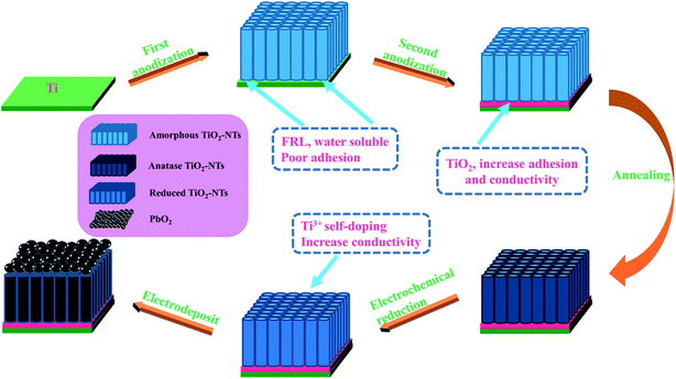
Lead nitrate medium is one of the most fashion media used for PbO2 electrodeposition. Besides that, lead acetate,39 lead methyl sulfonate,40 lead sulfamate,41 lead fluoroborate42 and other media have also been reported. In present research, TiO2-NTs may be used in Zn electrowinning anode for the first time. Titanium was selected as the substrate to fabricate TiO2-NTs in situ as the intermediate layer via anodization. Additional anodization, annealing and electrochemical reduction methods were used to enhance the conductivity of the nanotubes and adhesion. PbO2 was deposited on Ti/TiO2-NTs through galvanostatic deposition in lead acetate (Pb(CH3COO)2) medium and lead nitrate (Pb(NO3)2) medium. A novel Ti/TiO2-NTs/PbO2 material with excellent OER performance and good corrosion resistance was successfully prepared in the Pb(CH3COO)2 medium. The physical structure was studied by XRD and FE-SEM, and the electrochemical performance were tested by LSV, CV, EIS and Tafel. And the mechanisms of TiO2-NTs enhancing OER performance and corrosion resistance were explored.
2 Experimental
2.1 Preparation of Ti/TiO2-NTs
Titanium sheet (20 mm × 10 mm × 1 mm) was used to fabricate TiO2-NTs via anodization. First, the titanium sheet was chemically polished in a mixed solution of HF, HNO3 and deionized water in a ratio of 1![[thin space (1/6-em)]](https://www.rsc.org/images/entities/char_2009.gif) :1:2 for 10 s. Then it was ultrasonic for 5 min in anhydrous ethanol, acetone and deionized water, respectively, following dried in the air for 20 min. After that, each titanium sheet was anodized 2 times, with titanium sheet as the anode and stainless steel as the cathode. Step 1: the anodization occurred in 100 ml ethylene glycol (EG) solution containing 0.3 wt% NH4F and 2 vol% deionized water, DC supply voltage 60 V, time 1 h. Step 2: it was transferred to 100 ml ethylene glycol solution containing 5 wt% H3PO4 and oxidized for 1 min so as to eliminate the influence of fluorine-rich layer (FRL) and increase the adhesion of nanotube layer and conductivity.43 Finally, it was annealed for 3 h at an air atmosphere of 450 °C with a heating rate of 3 °C min−1 so that amorphous TiO2-NTs was converted to anatase.
:1:2 for 10 s. Then it was ultrasonic for 5 min in anhydrous ethanol, acetone and deionized water, respectively, following dried in the air for 20 min. After that, each titanium sheet was anodized 2 times, with titanium sheet as the anode and stainless steel as the cathode. Step 1: the anodization occurred in 100 ml ethylene glycol (EG) solution containing 0.3 wt% NH4F and 2 vol% deionized water, DC supply voltage 60 V, time 1 h. Step 2: it was transferred to 100 ml ethylene glycol solution containing 5 wt% H3PO4 and oxidized for 1 min so as to eliminate the influence of fluorine-rich layer (FRL) and increase the adhesion of nanotube layer and conductivity.43 Finally, it was annealed for 3 h at an air atmosphere of 450 °C with a heating rate of 3 °C min−1 so that amorphous TiO2-NTs was converted to anatase.
2.2 Electrodeposition of PbO2
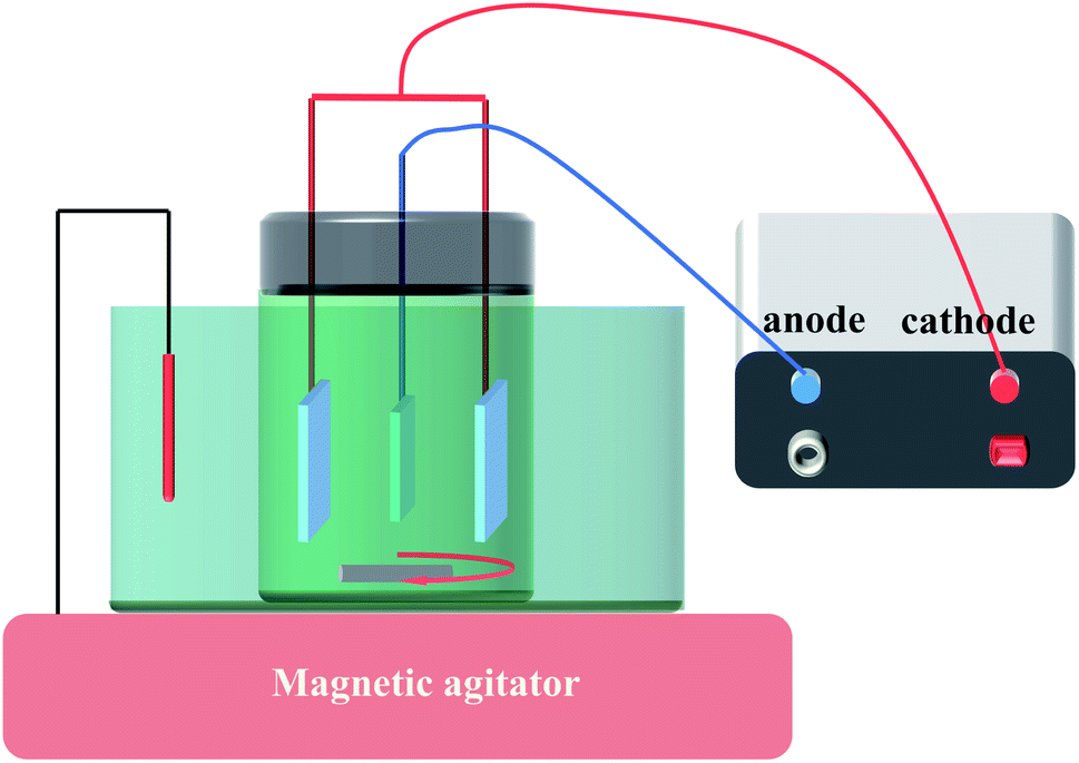
Before electrodeposition of PbO2, the electrochemical reduction of TiO2-NTs was conducted in 0.1 M H2SO4 solution for 5 min with the TiO2-NTs as the cathode and Pt sheet as the anode in order to improve the conductivity of TiO2-NTs as much as possible, current density 5 mA cm−2. Then, Ti sheet and Ti/TiO2-NTs were electrodeposited with PbO2 in lead acetate medium (I) containing 0.2 M Pb(CH3COO)2 and 0.2 M Na(CH3COO), respectively, and marked as Ti/PbO2 (I) and Ti/TiO2-NTs/PbO2 (I). In addition, PbO2 was deposited on Ti/TiO2-NTs in lead nitrate medium (II) containing 0.1 M HNO3 and 0.2 M Pb(NO3)2, and marked as Ti/TiO2-NTs/PbO2 (II). Ti sheet and Ti/TiO2-NTs are the working electrode and stainless steel is the counter electrode, current density 20 mA cm−2, temperature 40 °C, magnetic stirring speed 300 rpm, and electrodeposition time 1 h. The general experimental procedures are shown in Fig. 1 and the experimental installation are shown in Fig. 2.
 |
| | Fig. 1 The general experimental procedures of the work. | |
 |
| | Fig. 2 Experimental installation. | |
2.3 Characterization of materials
The phase structure and surface morphology of the materials were characterized by D/max2200 X-ray diffractometer (XRD, Cu Kα radiation) and a Nova Nano-SEM450 field emission scanning electron microscope (FE-SEM) respectively. Linear Sweep Voltammetry (LSV), cyclic voltammetry (CV), electrochemical impedance spectroscopy (EIS) and Tafel plots were tested by electrochemical workstation (CHI760E) under the three electrodes system. The electrolyte is Zn electrowinning simulation solution containing 50 g L−1 Zn2+ and 150 g L−1 H2SO4 at 35 °C.The composite materials were the working electrodes and only 1 cm2 was left as the working area. Mercuric Sulfate Electrode (MSE) was the reference electrode, and stainless steel was the counter electrode.
2.4 Stability
After Ti/TiO2-NTs/PbO2 (I) was prepared, the i–t curve was tested by chronoamperometry at an anodic potential of 2 V (vs. MSE) and the time of 27 h. Then, its XRD pattern and SEM image were collected in order to deeply analyze the microscopic changes of the material during use. In addition, a 5000-cycle CV scan was adopted, the voltage range was 0–2 V, and the scan rate was 0.05 V s−1, after that, the anodic polarization curve of the material was tested and compared with fresh Ti/TiO2-NTs/PbO2 (I).
3 Results and discussion
3.1 The phase structure and surface morphology
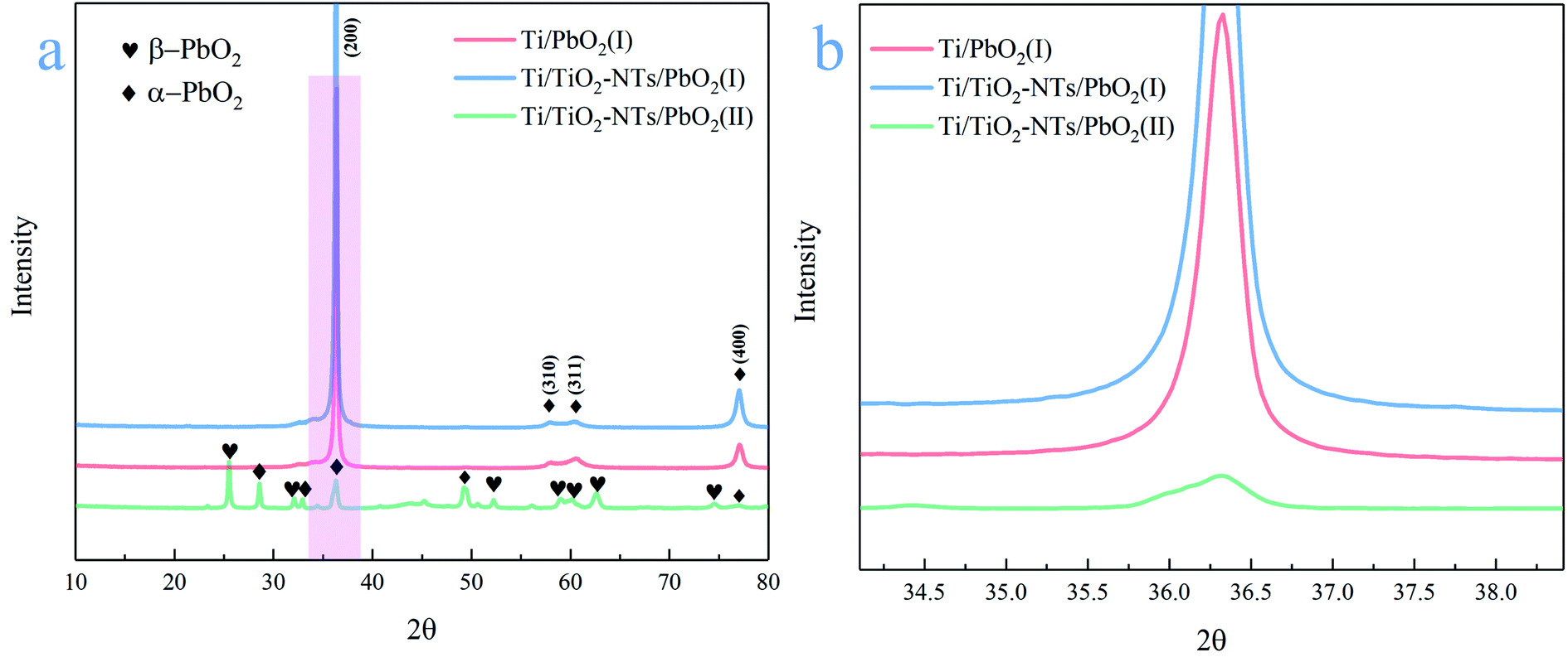
The phase composition of the active coating corresponding to Ti/PbO2 (I), Ti/TiO2-NTs/PbO2 (I) and Ti/TiO2-NTs/PbO2 (II) materials are shown in Fig. 3. As displayed in the Fig. 3a, The main diffraction peaks of Ti/PbO2 (I) and Ti/TiO2-NTs/PbO2 (I) appear in 36.37°, 58.12°, 60.74° and 77.23°and the corresponding crystal planes are (200), (310), (311) and (400), indicating that the phase only consists of α-PbO2 (PDF 72-2400), and preferential growth at (200) crystal planes can be seen obviously. The crystal planes (200) and (400) of Ti/TiO2-NTs/PbO2 (I) are stronger compared with Ti/PbO2 (I), suggesting that the introduction of TiO2-NTs is beneficial to the formation of PbO2 crystals. When the medium is changed into Pb(NO3)2, the phases of Ti/TiO2-NTs/PbO2 (II) consist of α-PbO2 and β-PbO2 (PDF 41-1492). The α-PbO2 that appears in 28.57°, 32.62°, 34.31°and 49.64° isn't found in Ti/PbO2 (I) and Ti/TiO2-NTs/PbO2 (I). This may also be because the (200) crystal plane preferentially grows obviously in the Pb(CH3COO)2 medium, which leads to the inconspicuous peaks of those angles. Besides that, in Fig. 3b, it can be obtained that the FWHM of Ti/PbO2 (I) (0.290 rad) is smaller than that of Ti/TiO2-NTs/PbO2 (I) (0.320 rad) in the (200) crystal plane by XRD analysis, revealing that TiO2-NTs promotes the formation of smaller PbO2 grains.
 |
| | Fig. 3 (a) XRD pattern of different PbO2 materials; (b) a partial enlarged view of the XRD pattern. | |
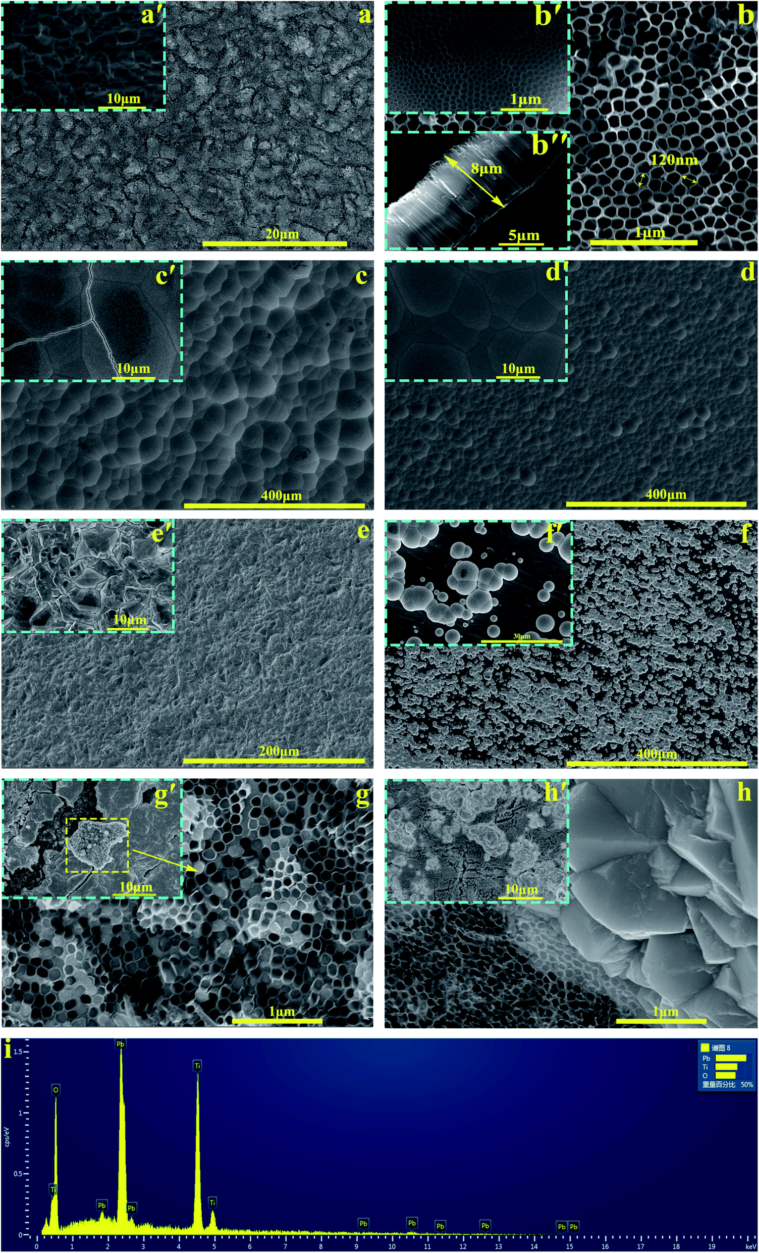
The SEM images of all samples are exhibited in the Fig. 4. The Ti sheet shows a rough surface after chemical polish (Fig. 4a′), which is conducive to the formation of TiO2-NTs since the surface electric field on flat surface is so scattered that it is easy to form irregular nanopores.44 Fig. 4a presents the surface after anodization, and some obvious change can be seen. Specifically, the detail can be observed in high magnification image (Fig. 4b, b'and b′′). A self-organized high aspect ratio TiO2-NTs layer is formed onto the surface of Ti sheet with a diameter of ∼120 nm, length of ∼8 μm and a closed bottom.
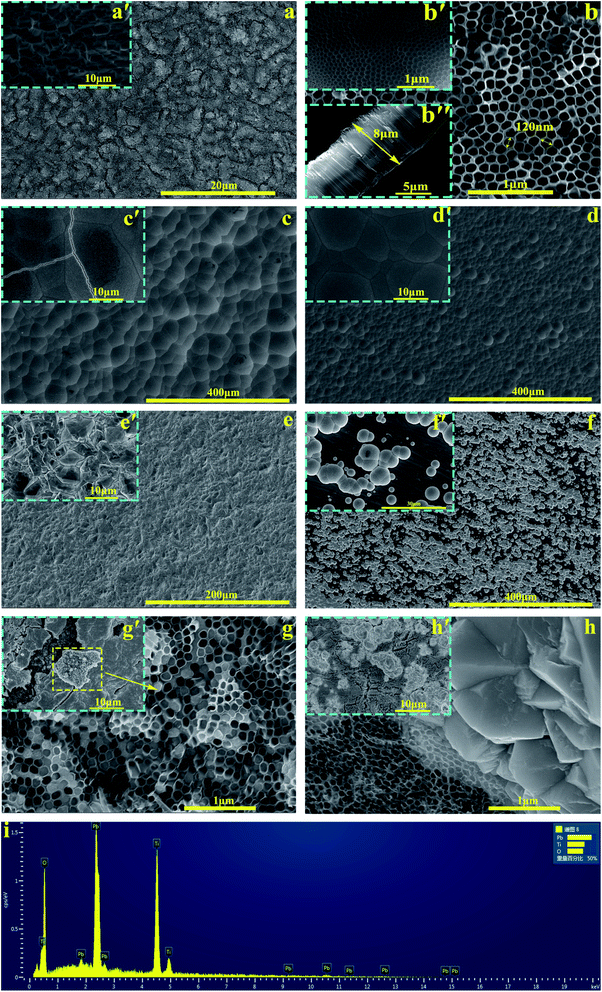 |
| | Fig. 4 SEM of different materials: (a) TiO2-NTs middle layer at low magnification and (a′) Ti sheet after chemical polishing; (b) TiO2-NTs at high magnification, (b′ and b′′) bottom and side of TiO2-NTs; (c–e) Ti/PbO2 (I), Ti/TiO2-NTs/PbO2 (I) and Ti/TiO2-NTs/PbO2 (II), deposition time 1 h; (f–h) Ti/PbO2 (I), Ti/TiO2-NTs/PbO2 (I) and Ti/TiO2-NTs/PbO2 (II), deposition time 3 min; (i) EDS of Ti/TiO2-NTs/PbO2 (I), deposition time 3 min. | |
The Fig. 4c and d represent the PbO2 deposited onto titanium without/with TiO2-NTs in the Pb(CH3COO)2 medium respectively. Comparing two images, it can be observed that the introduction of TiO2-NTs eliminates the cracks and refines the PbO2 crystal. In addition, the PbO2 coating presents a circle shape which is consistent with α-PbO2. The result agrees with the XRD pattern. The Fig. 4e is the morphology of PbO2 deposited onto Ti/TiO2-NTs in the Pb(NO3)2 medium. It can be seen that the PbO2 shows a pyramid shape of β-PbO2, which is totally different from that in the Pb(CH3COO)2 medium.
In order to better understand the behaviors of PbO2 deposition, the SEM images were captured while fixed deposition time was 3 min and shown in Fig. 4f–h. In the Fig. 4f (Ti/PbO2, Pb(CH3COO)2), there are only a small amount of PbO2 on Ti substrate. But it can be seen from Fig. 4g′ (Ti/TiO2-NTs/PbO2, Pb(CH3COO)2) that the Ti/TiO2-NTs surface is covered with a layer of PbO2, which demonstrates TiO2-NTs promotes the formation of PbO2. Moreover, the cross section of the nanotube was collected and shown in Fig. 4g (Ti/TiO2-NTs/PbO2, Pb(CH3COO)2). A great amount of nanotube channel is filled with PbO2, which has been confirmed in EDS results (Fig. 4i). However, in Fig. 4h (Ti/TiO2-NTs/PbO2, Pb(NO3)2) that is the deposition in the Pb(NO3)2 medium for 3 min, the PbO2 isn't found at the nanotube orifice, while it exists outside the nanotube. It suggests that PbO2 may preferentially grow outside the nanotube resulting in a low filling rate of PbO2 in the nanotube channel. In addition, in the Fig. 4h′, PbO2 does not completely cover Ti/TiO2-NTs surface, comparing with Fig. 4g′, which means that the deposition rate of PbO2 in the Pb(NO3)2 medium is slower than in the Pb(CH3COO)2 medium.
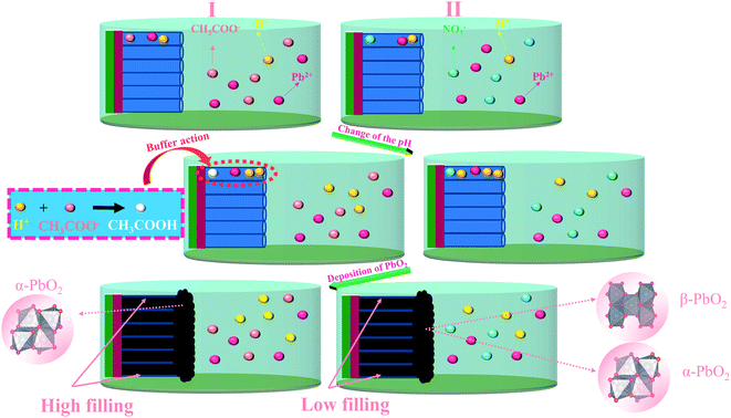
In general, the deposition behavior of PbO2 can be summarized. First of all, TiO2-NTs may be able to provide a larger surface area and more nucleation sites, resulting in an increase in nucleation rate and a decrease in PbO2 grain size. Moreover, it can eliminate the surface crack and increase the adhesion of PbO2 coating, Secondly, the deposition behavior of PbO2 in nanotube channel is different in the two media. According to a literature reported by Velichenko,45 the electrodeposition mechanism of PbO2 can be described as following:
| | |
H2O → OHads + H+ + e−
| (1) |
| | |
Pb2+ + OHads → Pb(OH)2+
| (2) |
| | |
Pb(OH)2+ + H2O → Pb(OH)22+ + H+ + e−
| (3) |
| | |
Pb(OH)22+ → PbO2 + 2H+
| (4) |
According to reactions (1–4), as the electrodeposition of PbO2 goes on, more H+ will produce, and the formation of PbO2 can be inhibited due to decrease of pH. When PbO2 is electrodeposited onto TiO2-NTs, the ion exchange is not timely due to the small diameter of the nanotube. The pH in the nanotube channel will decrease with the development of electrodeposition so that the continuous generation of PbO2 in the nanotube channel is inhibited. However, in the Pb(CH3COO)2 medium, the CH3COO− can play the role of buffer to effectively hinder the pH reduction. The PbO2 can be deposited gradually in channel, as shown in the Fig. 5. The nanotube channel has a high filling rate, which can cause the PbO2 coating and TiO2-NTs have a good combination.
 |
| | Fig. 5 Schematic diagram of the influence of deposition medium on PbO2 materials. | |
3.2 Oxygen evolution activity of the materials
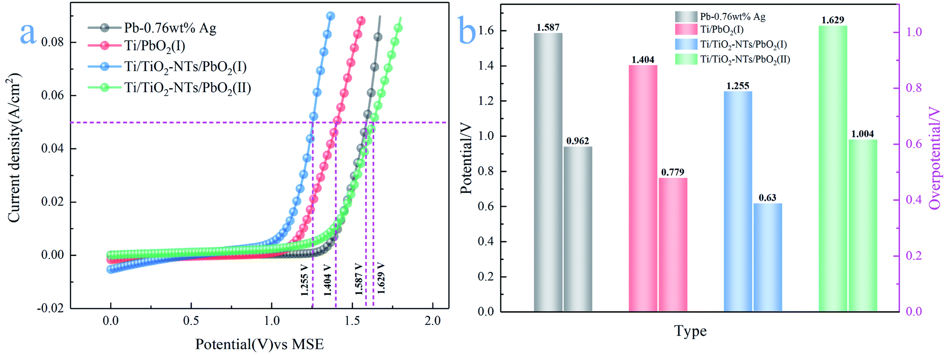
3.2.1 LSV curve analysis. In oxygen evolution kinetics, oxygen evolution overpotential oxygen evolution overpotential is, the easier it is to produce oxygen. In order to study the η parameters of these materials, LSV technology was adopted in simulated Zn electrowinning solution (50 g L−1 Zn2+, 150 g L−1 H2SO4), scanning rate 0.05 V s−1, temperature 35 °C. In addition, the LSV curve of Pb-0.76 wt% Ag was also tested in order to compare with it. The measured LSV curves and η value are shown in Fig. 6.
 |
| | Fig. 6 (a) Anode polarization curve of different PbO2 materials; (b) oxygen evolution potential and overpotential of different PbO2 materials. | |
Their OER catalytic activity can be visually compared from Fig. 6a. The catalytic activity from low to high is Ti/TiO2-NTs/PbO2 (II), Pb-0.76wt%Ag, Ti/PbO2 (I) and Ti/TiO2-NTs/PbO2 (I). It can be seen from Fig. 6b that the η of Pb-0.76 wt% Ag is 962 mV. The high η is one of the main reasons for high energy consumption in Zn electrowinning. The η of Ti/PbO2 (I) is 779 mV, although it is lower than Pb-0.76 wt% Ag, the PbO2 coating has a lot of cracks and poor adhesion, which is not an ideal electrode. However, Ti/TiO2-NTs/PbO2 (I) has the best oxygen evolution performance (η = 630 mV). Its η is 149 mV lower than that of Ti/PbO2 (I) and 332 mV lower than that of Pb-0.76 wt% Ag, indicating that the introduction of TiO2-NTs enhances the OER catalytic activity. Moreover, it is worth noting that the η of Ti/TiO2-NTs/PbO2 (II) (η = 1004 mV) has a significant increase compared with Ti/TiO2-NTs/PbO2 (I), which shows that Pb(CH3COO)2 medium may be more suitable for electrodeposition of PbO2 on TiO2-NTs in order to improve OER catalytic activity.
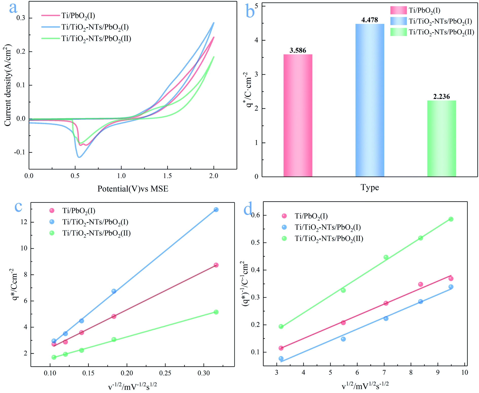
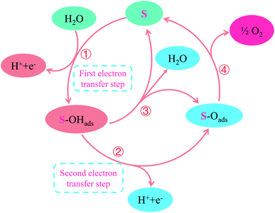
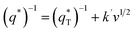
3.2.2 CV curves analysis. So far, OER mechanisms have been fully studied through dynamics and density functional theory (DFT), and one of the accepted mechanisms is shown in the Fig. 7.46–49 S represents the active sites on the oxide electrode, while OHads and Oads stand for the adsorbable hydroxyl and oxygen-group species, respectively. The S plays a crucial role in the whole reaction path. In the oxide electrode, only active sites can chemically adsorb and desorb intermediate products (OHads and Oads), thereby providing places for chemical reactions. Therefore, the larger the specific surface area, the more active sites, the stronger the oxygen evolution capacity. The specific surface areas can be qualitatively compared by obtaining the voltammetry charge (q*) from the integral CV curves, the larger the q*, the larger the specific surface area, at the same scanning rate (v).21
 |
| | Fig. 7 The oxygen evolution mechanism of PbO2 materials in acidic solution. | |
In this work, scan rates 0.01 V s−1, 0.03 V s−1, 0.05 V s−1, 0.07 V s−1 and 0.09 V s−1 were adopted, and the measured CV curves at 0.05 V s−1 are shown in the Fig. 8a. The following relations exist between q* and v:
| |
 | (5) |
| |
 | (6) |
| |
 | (7) |
The
k and
k′ are constants for the slope,

is the real charge on the surface of the electrode which consists of the outercharge

and the innercharge

The relationships of
q*
versus v−1/2 and (
q*)
−1 versus v1/2 is shown in
Fig. 8c and d.
 |
| | Fig. 8 (a) CV curves of different PbO2 materials; (b) voltammetry charge of different materials at 0.05 V s; (c) relationship of q* versus v−1/2; (d) relationship of (q*)−1 versus v1/2. | |
In the Fig. 8a, the CV curve of Ti/PbO2 (I) is smaller than Ti/TiO2-NTs/PbO2 (I), and Ti/TiO2-NTs/PbO2 (II) has the smallest CV curve. The calculated q* at 0.05 V s−1 is shown in the Fig. 8b. The q* of Ti/PbO2 (I) is 3.586 C cm−2, after the introduction of TiO2-NTs, the q* of Ti/TiO2-NTs/PbO2 (I) increased to 4.478 C cm−2, which means that TiO2-NTs promote the formation of a larger specific surface area PbO2 coating. This may because TiO2-NTs can provide a large surface area for PbO2 nucleation, and the increase in nucleation rate leads to an increase in electrode surface area. However, the q* of Ti/TiO2-NTs/PbO2 (II) is the smallest. The result shows that the specific surface area of PbO2 electrodeposited in the Pb(CH3COO)2 medium are larger than those in the Pb(NO3)2 medium. It may due to PbO2 with a smaller grain size can be obtained in the Pb(CH3COO)2 medium, resulting in a larger specific surface area. The similar laws about specific surface area at different scan rates also can be found in Fig. 8c and d. These corresponds to LSV curves characteristics in the previous section.
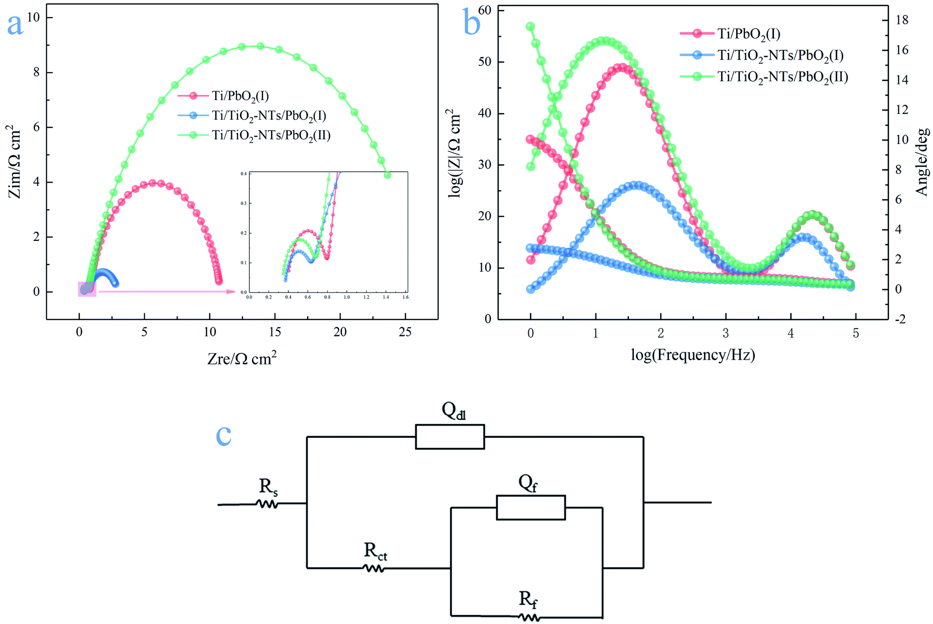
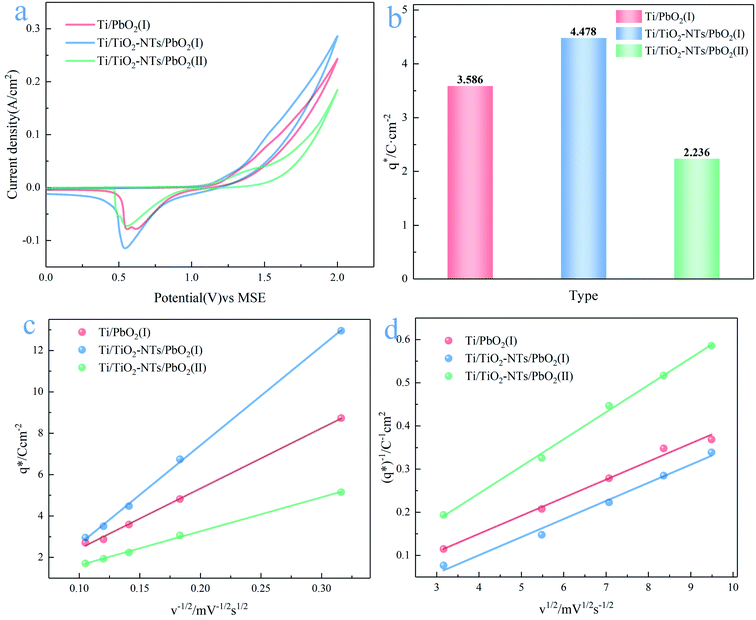
3.2.3 EIS analysis. According to the OER mechanism in the Fig. 7, OER begins with the transfer of the first charge and generates OHads, then the second charge transfers and generates Oads.46 It is worth mentioning that the first charge transfer step is the rate-determining step (RDS) of OER, which has been confirmed by many researchers and is called primary water discharge.50 The conductivity of the electrode material determines the rate of charge transfer and affects the rate of OER. Therefore, in order to further study the factors affecting the catalytic activity of OER, EIS technology was adopted at an anodic potential of 1.4 V (vs. MSE). The measured EIS curves are shown in the Fig. 9.
 |
| | Fig. 9 (a) Nyquist plots of different PbO2 materials; (b) Bode plots of different PbO2 materials; (c) equivalent circuit of OER on the PbO2 materials in the simulated solution (50 g L−1 Zn2+, 150 g L−1 H2SO4) at 35 °C. | |
There are two semicircles in the Nyquist plots (Fig. 9a) and two peaks in the Bode plots (Fig. 9b), indicating the existence of two time-constant. The phenomenon exists in the following cases, such as the generation of solid electrolyte interface (SEI) membranes in lithium ion batteries, the occurrence of side reactions in metal corrosion, intermediates adsorption and desorption in the reaction process and so on. Electrochemical impedance spectroscopy usually consists of three parts: the high frequency semicircle is mainly the capacitive behavior due to the above situations, the middle frequency semicircle represents the impedance behavior due to charge transfer, and the straight line at low frequency is the Warburg impedance.51 The Nyquist plots are calculated using the R(Q(R(QR))) equivalent circuit,52 as shown in the Fig. 9c. Rf, Rct and Rs represent adsorption impedance of OHads and Oads, charge transfer resistance and solution resistance, respectively. Qf and Qdl are constant phase elements (CPE), because the surface of electrode materials is not an ideal plane, and the electrochemical properties of the electrode surface vary from place to place, resulting in the dispersion of resistance and capacitance. The characteristic values of capacitance can be calculated by the following formulas:53
| | |
C = Q1/n(RS−1 + Rct−1)(n−1)/n
| (8) |
When
Rct »
Rs
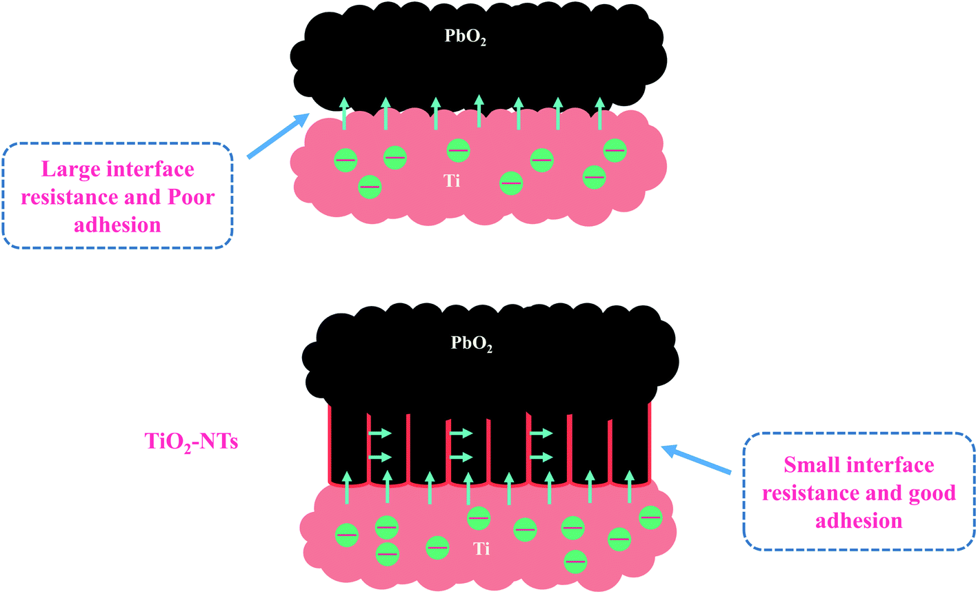
The simulation results of each parameter in the equivalent circuit are listed in the Table 1. The Rs maintaining around 0.33–0.39 (Ω cm2) indicates the stability of the test solution, and Rf maintains 0.269–0.415(Ω cm2). Some interesting phenomena are found about Rct. First, by comparing Ti/PbO2 (I) and Ti/TiO2-NTs/PbO2 (I), it can be found that TiO2-NTs as an intermediate layer reduces Rct (10.01 Ω cm2 to 2.337 Ω cm2). This probably due to TiO2-NTs can provide a large contact area with PbO2 coating, which reduces the interface resistance, as shown in the Fig. 10. Subsequently, when the electrodeposition medium is changed from Pb(CH3COO)2 to Pb(NO3)2, the Rct shows a significant increase (2.337 Ω cm2 to 25.4 Ω cm2). It may be because the PbO2 deposited in the Pb(NO3)2 medium can't fill the nanotube channel well, which isn't conducive to electron transport, as shown in the Fig. 5 in the SEM discussion.
Table 1 Parameter values of different PbO2 materials obtained by equivalent circuit simulation
| Type |
Rs/Ω cm2 |
Rf/Ω cm2 |
Qf/mΩ−1 sn cm−2 |
Cl/mF cm−2 |
Rct/Ω cm2 |
Qdl/mΩ−1 sn cm−2 |
Cdl/mF cm−2 |
| Ti/PbO2 (I) |
0.389 |
0.415 |
0.025 (n = 1) |
0.025 |
10.01 |
4.98 (n = 0.853) |
5.581 |
| Ti/TiO2-NTs/PbO2 (I) |
0.363 |
0.269 |
0.046 (n = 1) |
0.046 |
2.337 |
18.63 (n = 0.705) |
41.454 |
| Ti/TiO2-NTs/PbO2 (II) |
0.334 |
0.353 |
0.029 (n = 1) |
0.029 |
25.4 |
7.592 (n = 0.782) |
9.838 |
 |
| | Fig. 10 Schematic diagram of the influence of TiO2-NTs on materials. | |
The electrocatalytic activity of Ti/TiO2-NTs/PbO2 is compared with some reported materials. As shown in Table 2 and Fig. 11.
Table 2 Comparison of related materials for OER electrocatalytic activity
| Electrodes |
Concentration of H2SO4 |
η/mV (vs. NHE, 50 mA cm−2) |
Reference |
| Ti/Sb–SnO2/Bi–PbO2 |
0.5 M |
1046 |
54 |
| Al/Pb–PANI–WC |
1.53 M |
941 |
8 |
| Pure Pb |
1.8 M |
936 |
55 |
| PbO2–Co3O4 |
1.63 M |
858 |
56 |
| PANI/CeO2/WC |
1.53 M |
856 |
57 |
| Pb–CeO2 |
1.63 M |
826 |
58 |
| Pb–Co3O4 |
1.53 M |
792 |
56 |
| 3D-Pb–Ag/F–PbO2 |
1.53 M |
772 |
59 |
| Pb–MnO2 |
1.63 M |
765 |
60 |
| 3D-Ti/PbO2 |
1.53 M |
758 |
14 |
| PbO2–MnO2 |
1.63 M |
719 |
61 |
| Ti/PbO2–CeO2–graphite |
1.53 M |
648 |
19 |
| Ti/TiO2-NTs/PbO2 |
1.53 M |
630 |
This work |
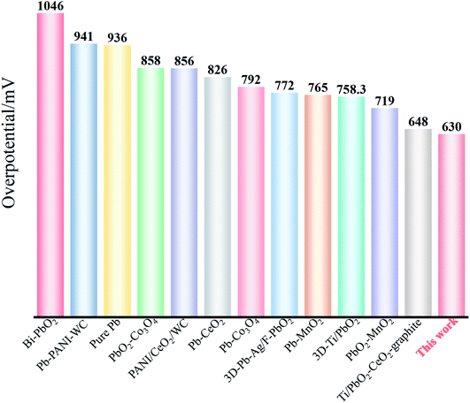 |
| | Fig. 11 Oxygen evolution overpotentials of different composite materials at 50 mA cm−2. | |
It can be seen from Fig. 11 that Ti/TiO2-NTs/PbO2 (I) exhibits an excellent OER electrocatalytic activity, and its oxygen evolution overpotential is only 630 mV. This outstanding oxygen evolution performance is mainly attributed to the nanotube structure of TiO2-NTs and the choice of lead acetate medium. The nano-channel structure provides a large surface area for PbO2 electrodeposition, refines the PbO2 grains, and increases the specific surface area of the deposits. The choice of lead acetate medium can make the nanotube channel better filled, which greatly reduces the internal resistance of the material. Therefore, Ti/TiO2-NTs/PbO2 (I) composite material presents an excellent OER electrocatalytic activity.
3.3 Corrosion resistance
Long service life of the electrode is necessary, which is one of the effective ways to save cost. Tafel technology can measure the self-corrosion current (icorr) of different PbO2 electrode materials, which can be used as one of the criteria to evaluate the service life. The lower the self-corrosion current, the better the corrosion resistance of the electrode. The Tafel plots measured in the simulated solution are shown in Fig. 12a, the temperature is 35 °C, and the scanning rate is 0.001 V s−1. The self-corrosion current obtained by electrochemical workstation analysis is shown in Fig. 12b.
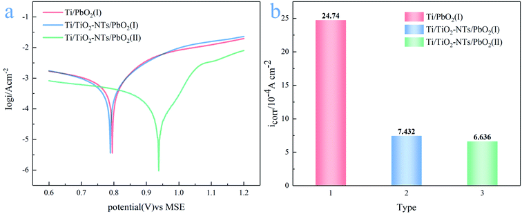 |
| | Fig. 12 (a) Tafel plots of different PbO2 materials at scan rate 0.001 V s; (b) self-corrosion current of different PbO2 materials in the simulated solution at 35 °C. | |
It can be seen from the Fig. 12b that the self-corrosion current of Ti/PbO2 (I), Ti/TiO2-NTs/PbO2 (I) and Ti/TiO2-NTs/PbO2 (II) are 2.474 × 10⁻³, 7.432 × 10⁻⁴ and 6.636 × 10⁻⁴(A cm−2) respectively. The self-corrosion current of Ti/TiO2-NTs/PbO2 (I) is smaller than that of Ti/PbO2 (I), which indicates that TiO2-NTs as an intermediate layer can increase corrosion resistance. It may be because TiO2-NTs can effectively prevent the electrolyte from contacting and corroding the Ti substrate, and it can also eliminate the surface cracks of the PbO2 coating. In addition, the icorr of Ti/TiO2-NTs/PbO2 (II) has slight decrease compared with Ti/TiO2-NTs/PbO2 (I), which may be associated with the different crystal structure of PbO2, but the too high oxygen evolution overpotential indicates that it is not an ideal anode for Zn electrowinning.
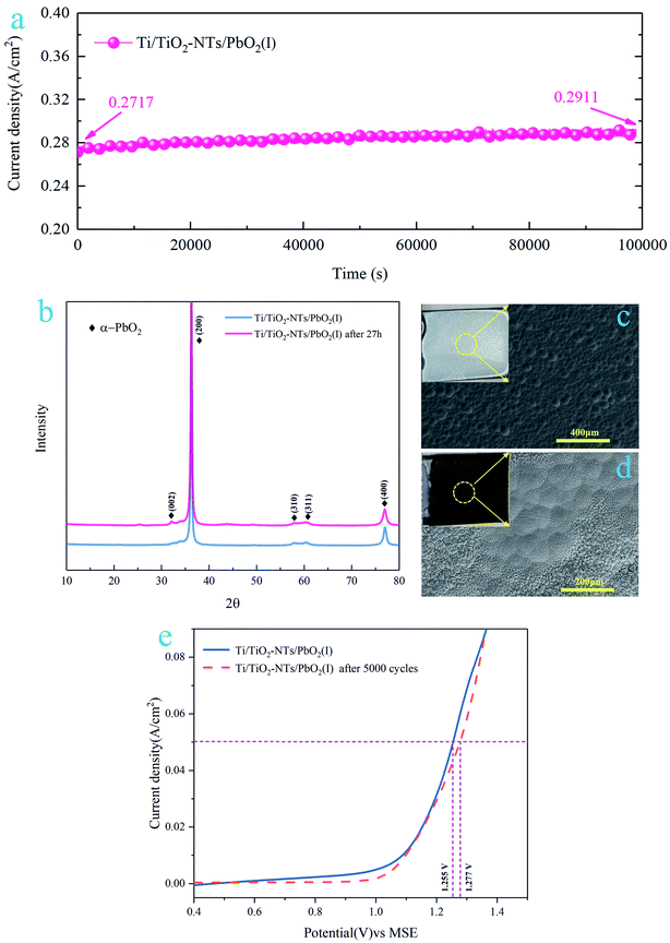
3.4 Stability of the Ti/TiO2-NTs/PbO2 (I)
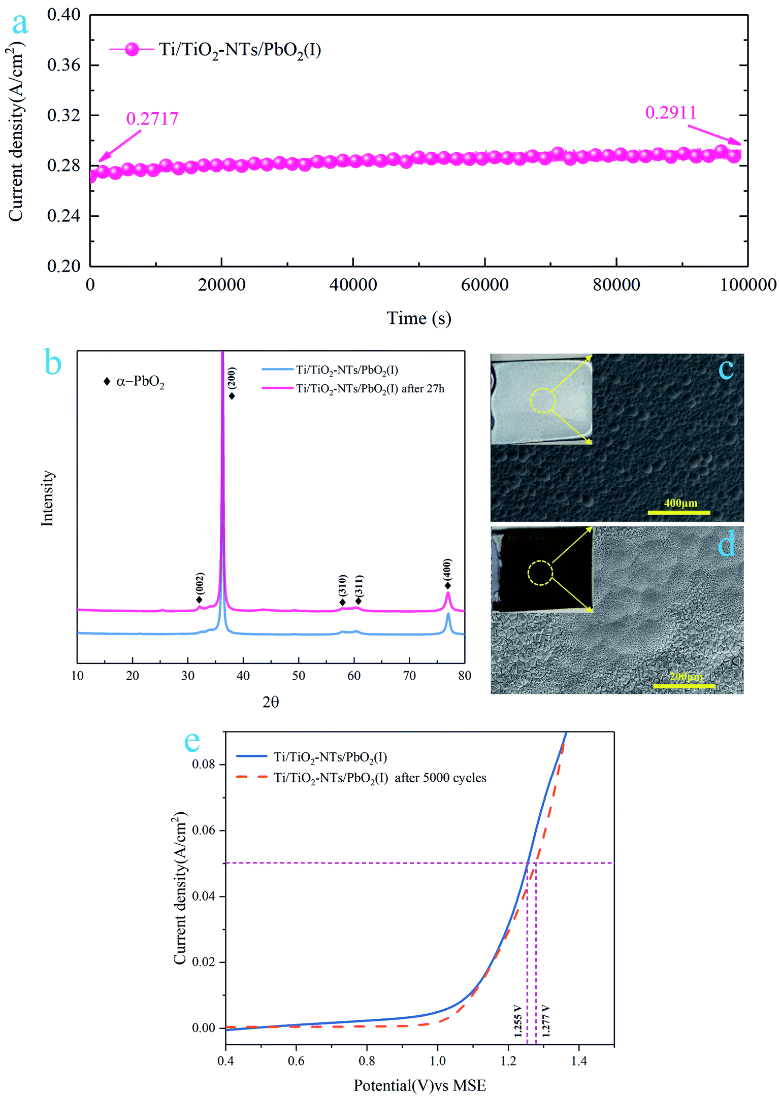
In order to test the stability of Ti/TiO2-NTs/PbO2 (I), a 27 h chronoamperometry was performed under a 2 V anodic potential, and the XRD pattern and SEM images were collected after the test. In addition, a 5000-cycle CV scan was adopted, the voltage was 0–2 V, and the scan rate was 0.05 V s−1, and then the LSV curve of Ti/TiO2-NTs/PbO2 (I) was measured. The results are shown in Fig. 13.
 |
| | Fig. 13 (a) Chronoamperometry curve of Ti/TiO2-NTs/PbO2 (I); (b) XRD pattern of Ti/TiO2-NTs/PbO2 (I) after 27 h chronoamperometry test; (c) SEM image of fresh Ti/TiO2-NTs/PbO2 (I); (d) SEM image of Ti/TiO2-NTs/PbO2 (I) after 27 h chronoamperometry test; (e) LSV curve of Ti/TiO2-NTs/PbO2 (I) after 5000 cycles of CV scan. | |
It can be seen from Fig. 13a that the current density increases slightly with time. After 27 h, it increases from 271.7 mA cm−2 to 291.1 mA cm−2, which indicates that the OER electrocatalytic activity of Ti/TiO2-NTs/PbO2 (I) is enhanced. After the 27 h chronoamperometry test, as shown in Fig. 13b, it can be observed that the XRD pattern of Ti/TiO2-NTs/PbO2 (I) only appears a new characteristic peak located at 32.62°. This corresponds to the (002) crystal plane of α-PbO2 (PDF 72-2400), which means that no new substance is generated. Interestingly, the surface becomes rougher and presents a cone shape similar to β-PbO2 (Fig. 13c and d), which is beneficial to the increase of the specific surface area to enhance the OER electrocatalytic activity. This conforms to the law presented in Fig. 13a. In addition, in Fig. 13e, Ti/TiO2-NTs/PbO2 (I) still exhibits a stable anodic polarization curve after 5000 cycles of CV scanning, and its oxygen evolution overpotential has only increased by 22 mV at 50 mA cm−2 compared with fresh Ti/TiO2-NTs/PbO2 (I). All these indicate that the composite material possesses an excellent stability and long-term application potential in acidic media.
4 Conclusion
On the whole, a novel Ti/TiO2-NTs/PbO2 composite material for Zn electrowinning was successfully synthesized in the Pb(CH3COO)2 medium. TiO2-NTs with a diameter of ∼120 nm, a length of ∼8 μm and uniform arrangement was obtained via anodization in ethylene glycol electrolyte containing 0.3wt%NH4F and 2% vol deionized water. In the Pb(CH3COO)2 medium, TiO2-NTs as an intermediate layer can make the PbO2 coating have small grains, few cracks, and large surface area (4.478 C cm−2 and 41.454 mF cm−2). Moreover, TiO2-NTs channel can be well filled by PbO2, which results in a low charge transfer resistance (2.337 Ω cm2). In addition, it can act as a barrier layer to increase the corrosion resistance (24.74 × 10⁻⁴ A cm−2 to 7.432 × 10⁻⁴ A cm−2). Therefore, the electrochemical performance is enhanced through the modification of TiO2-NTs. The oxygen evolution overpotential of Ti/TiO2-NTs/PbO2 (I) (η = 630 mV) is 332 mV lower than that of Pb-0.76 wt% Ag (η = 962 mV) under current density 50 mA cm−2 in the Zn electrowinning simulation solution (50 g L−1 Zn2+, 150 g L−1 H2SO4) at 35 °C and only increases 22 mV after 5000 cycles of CV scanning. These results indicate that Ti/TiO2-NTs/PbO2 prepared in Pb(CH3COO)2 medium may be an ideal Zn electrowinning anode material.
Conflicts of interest
There are no conflicts to declare.
Acknowledgements
The authors gratefully acknowledge the financial support of the National Natural Science Foundation of China (Project No. 51874154), the Key Project of Yunnan Province Science and Technology Plan of China (Project No. 2014FA024), the Specialized Research Fund for the Doctoral Program of the Ministry of Education of China (Project No. 20125314110011), and the Analysis and Measurement Fund (2019M20182102009) of Kunming University of Science and Technology.
References
- W. Wang, T. Yuan, R. Li, X. Zhu, H. Li, W. Lin, L. Li and D. Zheng, J. Electroanal. Chem., 2019, 847 Search PubMed.
- P. Li, Q. Cai and B. Wei, Eng. Failure Anal., 2006, 13, 876–885 CrossRef CAS.
- E. Abkhoshk, E. Jorjani, M. S. Al-Harahsheh, F. Rashchi and M. Naazeri, Hydrometallurgy, 2014, 149, 153–167 CrossRef CAS.
- Y. Haitao, C. Buming, L. Jianhua, G. Zhongcheng, Z. Yongchun and X. ruidong, Rare Met. Mater. Eng., 2014, 43, 2889–2892 CrossRef.
- W. Wang, R. Li, T. Yuan, X. Zhu, H. Li, W. Lin and L. Li, Hydrometallurgy, 2020, 192 CAS.
- W. Zhang and G. Houlachi, Hydrometallurgy, 2010, 104, 129–135 CrossRef CAS.
- N. Sorour, C. Su, E. Ghali and G. Houlachi, Electrochim. Acta, 2017, 258, 631–638 CrossRef CAS.
- R. D. Xu, L. P. Huang, J. F. Zhou, P. Zhan, Y. Y. Guan and Y. Kong, Hydrometallurgy, 2012, 125–126, 8–15 CrossRef CAS.
- Y. Li, L. X. Jiang, X. J. Lv, Y. Q. Lai, H. L. Zhang, J. Li and Y. X. Liu, Hydrometallurgy, 2011, 109, 252–257 CrossRef CAS.
- L. Yanqing, J. Liangxing, L. Jie, Z. Shuiping, L. Xiaojun, P. Hongjian and L. Yexiang, Hydrometallurgy, 2010, 102, 81–86 CrossRef.
- S. Chen, B. Chen, S. Wang, W. Yan, Y. He, Z. Guo and R. Xu, J. Alloys Compd., 2020, 815 Search PubMed.
- J. Yang, Q. Wang, J. Zhou, Q. Shen, L. Cao and J. Yang, Sep. Purif. Technol., 2020, 250 Search PubMed.
- Y. Zheng, W. Su, S. Chen, X. Wu and X. Chen, Chem. Eng. J., 2011, 174, 304–309 CrossRef CAS.
- X. Wang, R. Xu, S. Feng, B. Yu and B. Chen, RSC Adv., 2020, 10, 1351–1360 RSC.
- R. K. Karlsson and A. Cornell, Chem. Rev., 2016, 116, 2982–3028 CrossRef CAS.
- Y. Yao, G. Teng, Y. Yang, C. Huang, B. Liu and L. Guo, Sep. Purif. Technol., 2019, 211, 456–466 CrossRef CAS.
- M. Xu, Z. Wang, F. Wang, P. Hong, C. Wang, X. Ouyang, C. Zhu, Y. Wei, Y. Hun and W. Fang, Electrochim. Acta, 2016, 201, 240–250 CrossRef CAS.
- Q. Dai, Y. Xia and J. Chen, Electrochim. Acta, 2016, 188, 871–881 CrossRef CAS.
- C. Zhang, J. Liu and B. Chen, Ceram. Int., 2018, 44, 19735–19742 CrossRef CAS.
- C. Tang, Y. Lu, F. Wang, H. Niu, L. Yu and J. Xue, Electrochim. Acta, 2020, 331 Search PubMed.
- W. Zhao, J. Xing, D. Chen, Z. Bai and Y. Xia, RSC Adv., 2015, 5, 26530–26539 RSC.
- L. Chang, Y. Zhou, X. Duan, W. Liu and D. Xu, J. Taiwan Inst. Chem. Eng., 2014, 45, 1338–1346 CrossRef CAS.
- J. Bao, N. Lin, J. Guo, W. Gao, Z. Liu and H. Lin, J. Colloid Interface Sci., 2020, 574, 377–384 CrossRef CAS.
- A. B. Velichenko, V. A. Knysh, T. V. Luk'yanenko, Y. A. Velichenko and D. Devilliers, Mater. Chem. Phys., 2012, 131, 686–693 CrossRef CAS.
- Y. Li, L. Jiang, F. Liu, J. Li and Y. Liu, RSC Adv., 2014, 4, 24020–24028 RSC.
- S. lijima, Nature, 1991, 354, 56–58 CrossRef.
- V. Zwilling, E. Darque-Ceretti, A. Boutry-Forveille, D. David, M. Y. Perrin and M. Aucouturier, Surface and Interface Analysis, 1999 Search PubMed.
- S. P. Albu, A. Ghicov, J. M. Macak and P. Schmuki, Phys. Status Solidi RRL, 2007, 1, R65–R67 CrossRef CAS.
- I. Paramasivam, J. M. Macak, T. Selvam and P. Schmuki, Electrochim. Acta, 2008, 54, 643–648 CrossRef CAS.
- D. Wang, B. Yu, C. Wang, F. Zhou and W. Liu, Adv. Mater., 2009, 21, 1964–1967 CrossRef CAS.
- R. Beranek, H. Hildebrand and P. Schmuki, J. Electrochem. Soc., 2003, 6, B12–B14 CAS.
- J. M. Macak, S. P. Albu and P. Schmuki, Phys. Status Solidi RRL, 2007, 1, 181–183 CrossRef CAS.
- P. Roy, S. Berger and P. Schmuki, Angew. Chem., Int. Ed., 2011, 50, 2904–2939 CrossRef CAS.
- X. Chang, S. S. Thind and A. Chen, ACS Catal., 2014, 4, 2616–2622 CrossRef CAS.
- K. Aijo John, J. Naduvath, S. Mallick, T. Shripathi, M. Thankamoniamma and R. R. Philip, Nanoscale, 2015, 7, 20386–20390 RSC.
- G. Zhao, Y. Zhang, Y. Lei, B. Lv, J. Gao, Y. Zhang and D. Li, Environmaental Science & Techology, 2010 Search PubMed.
- J. Zhang, Y. Li, Y. Zhang, X. Qian, R. Niu, R. Hu, X. Zhu, X. Wang and J. Zhu, Nano Energy, 2018, 43, 91–102 CrossRef CAS.
- J. M. Macak, B. G. Gong, M. Hueppe and P. Schmuki, Adv. Mater., 2007, 19, 3027–3031 CrossRef CAS.
- R. Inguanta, F. Vergottini, G. Ferrara, S. Piazza and C. Sunseri, Electrochim. Acta, 2010, 55, 8556–8562 CrossRef CAS.
- I. Sirés, C. T. J. Low, C. Ponce-de-León and F. C. Walsh, Electrochim. Acta, 2010, 55, 2163–2172 CrossRef.
- H. Liu, S. Yu, T. Shen, S. Tong and C. Ma, Sep. Purif. Technol., 2014, 132, 27–32 CrossRef CAS.
- X. Zhong, F. Chen, H. Nie, R. Wang and Z. Xu, Hydrometallurgy, 2019, 190 Search PubMed.
- D. Yu, X. Zhu, Z. Xu, X. Zhong, Q. Gui, Y. Song, S. Zhang, X. Chen and D. Li, ACS Appl. Mater. Interfaces, 2014, 6, 8001–8005 CrossRef CAS.
- G. Z. Shiqi Li, D. Guo, L. Yu and W. Zhang, J. Phys. Chem. C, 2009, 113, 12759–12765 Search PubMed.
- A. B. Velichenko, R. Amadelli, E. V. Gruzdeva, T. V. Luk'yanenko and F. I. Danilov, J. Power Sources, 2009, 191, 103–110 CrossRef CAS.
- Q. Feng, Q. Wang, Z. Zhang, Y. Xiong, H. Li, Y. Yao, X.-Z. Yuan, M. C. Williams, M. Gu, H. Chen, H. Li and H. Wang, Appl. Catal., B, 2019, 244, 494–501 CrossRef CAS.
- J. Rossmeisl, A. Logadottir and J. K. Nørskov, Chem. Phys., 2005, 319, 178–184 CrossRef CAS.
- S. Laha, Y. Lee, F. Podjaski, D. Weber, V. Duppel, L. M. Schoop, F. Pielnhofer, C. Scheurer, K. Müller, U. Starke, K. Reuter and B. V. Lotsch, Adv. Energy Mater., 2019, 9, 1803795 CrossRef.
- H. Over, Chem. Rev., 2012, 112, 3356–3426 CrossRef CAS.
- F. R. Costa, D. V. Franco and L. M. Da Silva, Electrochim. Acta, 2013, 90, 332–343 CrossRef CAS.
- Y. Chen, Y. Zhang, B. Chen, Z. Wang and C. Lu, J. Power Sources, 2014, 256, 20–27 CrossRef CAS.
- S. Li, F. Wang, M. Xu, Y. Wang, W. Fang and Y. Hu, J. Electrochem. Soc., 2013, 160, E44–E48 CrossRef CAS.
- B. Hirschorn, M. E. Orazem, B. Tribollet, V. Vivier, I. Frateur and M. Musiani, Electrochim. Acta, 2010, 55, 6218–6227 CrossRef CAS.
- W. Yang, W. Yang and X. Lin, Appl. Surf. Sci., 2012, 258, 5716–5722 CrossRef CAS.
- Y. S. I. Ivanov and Z. Noncheva, Hydrometallurgy, 2000, 57, 125–139 CrossRef.
- J. Zhang, R. Xu, B. Yu, Y. He, Y. Li and Z. Qin, RSC Adv., 2017, 7, 49166–49176 RSC.
- L. Jin, H. Huang, Y. Fei, H. Yang, H. Zhang and Z. Guo, Hydrometallurgy, 2018, 176, 201–207 CrossRef CAS.
- Z. W. Wenjun Wang and D. Zheng, Hydrometallurgy, 2019, 183, 221–229 CrossRef.
- B. Chen, W. Yan, Y. He, H. Huang, H. Leng, Z. Guo and J. Liu, J. Electrochem. Soc., 2019, 166, E119–E128 CrossRef CAS.
- R. Ma, S. Cheng, X. Zhang, S. Li, Z. Liu and X. Li, Hydrometallurgy, 2016, 159, 6–11 CrossRef CAS.
- R. X. Jiong Wang, Materials Reports, 2017, 8, 35–40 CrossRef.
|
| This journal is © The Royal Society of Chemistry 2021 |
Click here to see how this site uses Cookies. View our privacy policy here. 
 Open Access Article
 This Open Access Article is licensed under a Creative Commons Attribution-Non Commercial 3.0 Unported Licence
 a,
Xuanbing Wang
a,
Xuanbing Wang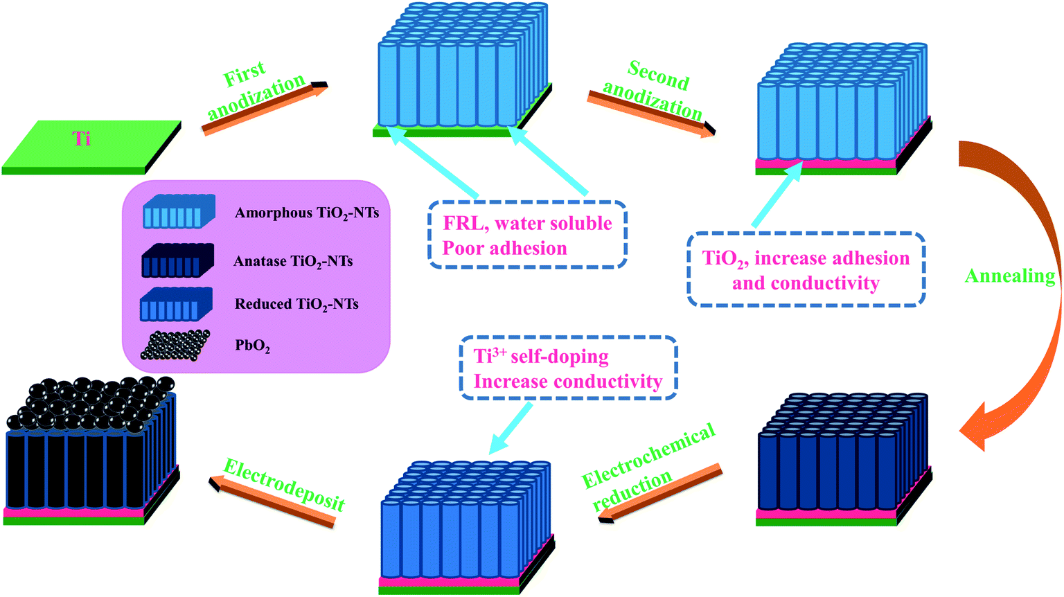


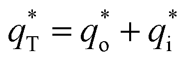
 is the real charge on the surface of the electrode which consists of the outercharge
  and the innercharge
  The relationships of q* versus v−1/2 and (q*)−1 versus v1/2 is shown in Fig. 8c and d.