 Open Access Article
SiOx-based graphite composite anode and efficient binders: practical applications in lithium-ion batteries†
Yonglian Xiong *,
Houchao Xing,
Yongsheng Fan
 ,
Ying Wei,
Jin Shang,
Yuwei Chen and
Jun Yan
College of Automotive Engineering, Yancheng Institute of Technology, Yancheng, Jiangsu 224051, China. E-mail: serena77@126.com
First published on 17th February 2021
Abstract
In recent years, graphite containing some proportion of SiOx-based materials for lithium-ion batteries has been investigated widely owing to its high specific capacity. An efficient binder is critical to maintain both the electronic and mechanical integrity of the SiOx-based graphite composite anode electrodes. In this study, we present a discussion on the water-soluble binders of styrene butadiene rubber (SBR) and poly acrylic acid (PAA) in a 15% SiOx–graphite composite anode with half cell (coin) and high voltage pouch battery. The peeling strength of the anode electrode using two binders was measured. The first coulombic efficiency and discharge specific capacity of SiOx–graphite was 83.6% and 626.5 mA h g−1 using the SBR as binder, while 81.2% and 636.1 mA h g−1 using the PAA binder, respectively. Based on the results from EIS, rate performance and the mechanism of the SBR emulsion binder, SBR binder is more conducive to the transfer of electrons and ions on the electrodes. In practical applications (high voltage pouch battery), the batteries with the PAA binder show better cycle performance and achieve lower swelling (7.49%) compared with those with the SBR binder (9.56%) at the 450th cycle in the range of 2.75–4.35 V.
1. Introduction
For boosting the increasing specific energy requirements for future electric equipment, the development of high capacity density materials is crucial.1–5 Silicon (Si) has received intensive attention as a promising anode material for lithium-ion batteries (LIBs) owing to its high specific capacity of 4200 mA h g−1 in the recent years. Nevertheless, the Si-based anode electrode suffers from around 300% of volume expansion during the charge and discharge process, which leads to the subsequent pulverization of the Si anode electrode and causes poor electrochemical performance and hinders its wide commercialization in LIBs.6,7 Silicon oxide (SiOx) is regarded as another promising anode material for LIBs due to its high specific capacity and improved cycling performance, particularly less expansion compared with the Si-based material during lithiation. SiOx has been widely concerned because of its high capacity of 1000–2000 mA h g−1, improved electrochemical performance and around 50% volume expansion of ∼1000 mA h g−1.8 However, the formation of lithium oxide during the lithiation process consumes lots of lithium ions, resulting in low 1st coulombic efficiency, which is generally lower than 80%.9 Combined with the application of materials and overcoming the above-mentioned shortcomings, an effective binder is crucial to keep the electrical contact between the particles, conductive agent and current collector and improve the electrochemical performance.10,11It is well known that water-soluble polymer binders are often used for Si-based and SiOx-based electrodes including polysaccharides, poly acrylic acid (PAA), polyacrylonitrile (PAN), polyimide (PI) and their derivatives.12–20 Recently, new type of binders are being explored for the Si-based anodes, such as self-healing polymer binders,21,22 and conductive binders.23–25 Magasinski et al. reported good electrochemical performance and low swelling obtained in the carbonate electrolyte with a PAA binder for Si-based anode.16 Song et al. reported an interpenetrated gel polymer binder, which was created via the in situ cross-linking of PAA and polyvinyl alcohol (PVA) precursors. It can effectively accommodate the large volume change during the charge and discharge processes. Excellent cycle performance and high coulombic efficiency were achieved even at a high current density.26 Xu et al. synthesized poly(acrylic acid)–poly(2-hydroxyethyl acrylate-co-dopamine) methacrylate as a binder for a silicon micro-particle anode, which showed special self-healing capability in situ formed during the electrode preparation. The cycle stability and rate performance remarkably improved due to the strong mechanical support and buffering of the strain caused by the volume expansion.22 In view of the above-mentioned binders, they usually contain special functional groups such as hydrophilic or multiple network formed structures.13–17 For example, PAA has a high density of carboxylic acid functional groups and forms strong hydrogen bonds on the Si-based or the SiOx-based anode surface. Polysaccharides and PVA contain hydroxyl groups, which form hydrogen bonds or ester bonds with –OH on the surface of the silicon oxide layer to interact with each other.27–29 A cross-linked polymeric binder with a 3D interconnected network of PAA and CMC inhibits the mechanical fracture during cycling and exhibits high reversible capacity.14 It was found that the Si-based or SiOx-based composite electrode using the above binders with high elastic modulus showed good electrochemical performance due to the high concentration of polar functional groups.
However, in addition to the electrochemical performance, the processing and manufacturing performance are also crucial for the bulk engineering applications. In the current practical applications, a commonly used binder, SBR combined with dispersant CMC, which mainly plays the role in the thickening and dispersal of the slurry, was used as the anode electrode. It is known that CMC shows some adhesion capacity, but it is only used on the thin electrode, the low press density or no need to press because of its brittleness. For the requirement of energy density, the electrodes often require high coating and press densities. In this case, CMC cannot be used as the binder and often used as a dispersant in the practical applications.
Compared with graphite, pure Si-based and SiOx-based anodes, the huge volume expansion during the lithiation process hinders the wide commercialization in LIBs. The forefront in research and development to address the above-mentioned challenges suggests the state of the art anode using graphite containing a small portion of SiOx-based materials in the practical applications. The state of the art anode in the enterprise application is often composed of graphite with a small proportion of Si-based or SiOx-based materials depending on its volume expansion during the lithiation and delithiation processes. Herein, in this study, two different binders, namely SBR and PPA, were chosen to investigate the application on a commercial graphite containing 15% SiOx anode material electrode. The electrochemical performance and processing capacity of the binders on the properties of the SiOx–graphite composite anode were explored and evaluated in coin cells and high voltage pouch cells.
2. Experimental section
Graphite (Hitachi Chemical Co. Ltd), SiOx (Shin-Etsu Chemical Co. Ltd), SBR (48%, JSR Corporation), CMC (Daicel Chemical Industries, Ltd), PAA (Mw: 400![[thin space (1/6-em)]](https://www.rsc.org/images/entities/char_2009.gif) 000, Sigma-Aldrich), lithium cobalt oxide (LCO, d50 23 μm, Umicore), conductive agent carbon black SP (TIMCAL) and carbon nanofiber VGCF (Showa Denko KK), polyvinylidene fluoride (PVDF, Kureha) were used as received.
000, Sigma-Aldrich), lithium cobalt oxide (LCO, d50 23 μm, Umicore), conductive agent carbon black SP (TIMCAL) and carbon nanofiber VGCF (Showa Denko KK), polyvinylidene fluoride (PVDF, Kureha) were used as received.
2.1. Electrode fabrication
The anode electrode was assembled by the mixture of SiOx–graphite (15![[thin space (1/6-em)]](https://www.rsc.org/images/entities/char_2009.gif) :
:![[thin space (1/6-em)]](https://www.rsc.org/images/entities/char_2009.gif) 85)
85)![[thin space (1/6-em)]](https://www.rsc.org/images/entities/char_2009.gif) :
:![[thin space (1/6-em)]](https://www.rsc.org/images/entities/char_2009.gif) VGCF
VGCF![[thin space (1/6-em)]](https://www.rsc.org/images/entities/char_2009.gif) :
:![[thin space (1/6-em)]](https://www.rsc.org/images/entities/char_2009.gif) CMC
CMC![[thin space (1/6-em)]](https://www.rsc.org/images/entities/char_2009.gif) :
:![[thin space (1/6-em)]](https://www.rsc.org/images/entities/char_2009.gif) SBR (PAA) with a weight ratio of 95
SBR (PAA) with a weight ratio of 95![[thin space (1/6-em)]](https://www.rsc.org/images/entities/char_2009.gif) :
:![[thin space (1/6-em)]](https://www.rsc.org/images/entities/char_2009.gif) 2
2![[thin space (1/6-em)]](https://www.rsc.org/images/entities/char_2009.gif) :
:![[thin space (1/6-em)]](https://www.rsc.org/images/entities/char_2009.gif) 1.5
1.5![[thin space (1/6-em)]](https://www.rsc.org/images/entities/char_2009.gif) :
:![[thin space (1/6-em)]](https://www.rsc.org/images/entities/char_2009.gif) 1.5. The cathode electrode was prepared by 96% LCO with 2% SP and 2% binder PVDF. An appropriate amount of deionized water for the anode and NMP for the cathode as solvents were added to obtain slurry, which was coated on the 8 μm Cu and 13 μm Al current collector. The loading density of the anode and cathode was about 13.2 and 43 mg cm−2 for the pouch cell, respectively, and the mean loading density of the anode for the coin cell was about 6.1 mg cm−2. The obtained anode and cathode electrodes were dried in a vacuum oven at 100 °C and 140 °C, respectively, until the moisture content was lower than 200 ppm with a Karl Fischer (KF) coulometric titrator (Mettler Toledo C30).
1.5. The cathode electrode was prepared by 96% LCO with 2% SP and 2% binder PVDF. An appropriate amount of deionized water for the anode and NMP for the cathode as solvents were added to obtain slurry, which was coated on the 8 μm Cu and 13 μm Al current collector. The loading density of the anode and cathode was about 13.2 and 43 mg cm−2 for the pouch cell, respectively, and the mean loading density of the anode for the coin cell was about 6.1 mg cm−2. The obtained anode and cathode electrodes were dried in a vacuum oven at 100 °C and 140 °C, respectively, until the moisture content was lower than 200 ppm with a Karl Fischer (KF) coulometric titrator (Mettler Toledo C30).
2.2. Battery preparation and electrochemical measurement
The materials and battery performance were investigated on a CR2430 coin cell and 423480 pouch cell, which was designed as high voltage system battery. 1.0 M LiPF6 was dissolved in a 6![[thin space (1/6-em)]](https://www.rsc.org/images/entities/char_2009.gif) :
:![[thin space (1/6-em)]](https://www.rsc.org/images/entities/char_2009.gif) 4 vol% mixture of diethylene carbonate (DEC) and ethylene carbonate (EC) with 15 wt% fluoroethylene carbonate (FEC) and 1 wt% additive vinylene carbonate (VC) as the electrolyte. Moreover, Toran polyethylene (PE) 16 μm was used as the separator. All the coin cells were tested at a current rate of 0.05C for the first two charge and discharge processes. The cycle performance and the rate performance were measured at room temperature in the range of 5–1500 mV on battery testing systems (Land CT2001A, Wuhan LAND Electronic Co. Ltd). Cyclic voltammetry (CV) was performed at a scan rate of 0.5 mV s−1 from 2 to 0 V on an electrochemical work station (CHI660E, CHI-Instrument, China). Moreover, electrochemical impedance spectra (EIS) from 100 mHz to 105 Hz were also measured on the CHI660E at an open-circuit voltage and the first Li lithiation (discharged) state with an amplitude of 5 mV. The cycle performance of the pouch cell was performed on an Arbin Battery Test Equipment (Arbin (5 A/5 V), America) in the voltage range of 2.75–4.35 V at room temperature. The thickness of the cell was measured every 50 cycles using a micrometer.
4 vol% mixture of diethylene carbonate (DEC) and ethylene carbonate (EC) with 15 wt% fluoroethylene carbonate (FEC) and 1 wt% additive vinylene carbonate (VC) as the electrolyte. Moreover, Toran polyethylene (PE) 16 μm was used as the separator. All the coin cells were tested at a current rate of 0.05C for the first two charge and discharge processes. The cycle performance and the rate performance were measured at room temperature in the range of 5–1500 mV on battery testing systems (Land CT2001A, Wuhan LAND Electronic Co. Ltd). Cyclic voltammetry (CV) was performed at a scan rate of 0.5 mV s−1 from 2 to 0 V on an electrochemical work station (CHI660E, CHI-Instrument, China). Moreover, electrochemical impedance spectra (EIS) from 100 mHz to 105 Hz were also measured on the CHI660E at an open-circuit voltage and the first Li lithiation (discharged) state with an amplitude of 5 mV. The cycle performance of the pouch cell was performed on an Arbin Battery Test Equipment (Arbin (5 A/5 V), America) in the voltage range of 2.75–4.35 V at room temperature. The thickness of the cell was measured every 50 cycles using a micrometer.
2.3. Characterization
Chemical compositions and crystalline structure of SiOx, graphite were investigated via X-ray diffraction (XRD) with Cu Kα radiation (λ = 1.54056 Å) (Rigaku D/max2500PC). The surface morphologies of the samples were tested via field-emission scanning electron microscopy (JSM-6360LV, Japan Electronics Co., Ltd Tokyo, Japan). The adhesion of the composite electrode was measured on a mechanical testing machine (Instron 2300) according to the 180 °C peel test. The tested electrode was made rectangular having the size of 270 × 44 mm, and then was pasted on the stainless steel testing plate with 3 M tape. The test speed was 300 mm min−1.3. Results and discussion
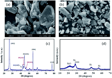
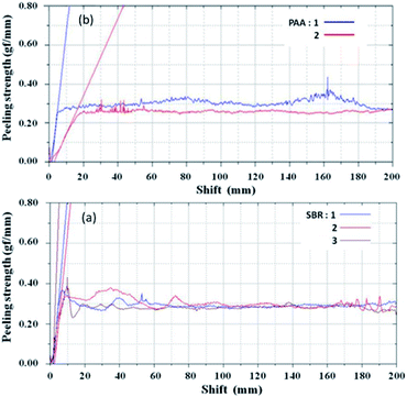
The morphologies of graphite and SiOx in this study are shown in Fig. 1a and b. The results indicate an average graphite particle size of 22 μm and polyhedral surface, which is beneficial for the contact of point-line-surface between the particles. The SiOx material was observed in the sheet shape and the particle size was of around 5 μm, which is conductive to the manufacturing process. It is known that the nanoparticles usually undergo dispersion agglomeration and have lower press density, which hinders their rapid commercial applications. Fig. 1c shows the typical characteristic peaks of graphite containing hexagonal and rhombohedral (3R) crystal structures in which the peaks at 43.5° and 46° are corresponding to the 3R (101) and (102) planes, respectively. Flandrois reported that the existence of the rhombohedral phase was beneficial to reduce the initial capacity loss at the first cycle.30 No sharp diffraction characteristic peak of SiOx is observed in Fig. 1d, which illustrates that the crystallinity of the SiOx material is low. The diffraction peaks of Si and a broad SiO peak are detected that are similar to that reported by Si and Yang et al.31,32 The first charge and discharge curves of the SiOx material in the range of 0–2 V are presented in Fig. S1.† Also, the first efficiency was 78.7% for which discharge and charge capacities were 1999.1 and 1574 mA h g−1, respectively.Fig. 2 shows the adhesion of two the anode electrodes (peeling strength) by the mechanical testing machine. When the PAA binder was used in the electrode, the results in terms of adhesion were found to be similar to those obtained when SBR was used as the binder. Also, the adhesion was enough and no active materials were sticking onto the roller in the process of rolling. The morphologies of anode electrodes after rolling are presented in Fig. S2.† Two anode electrodes showed good dispersion and no agglomeration. It can be seen that the conductive agent VGCF can maintain good electronic contact among the active material particles.
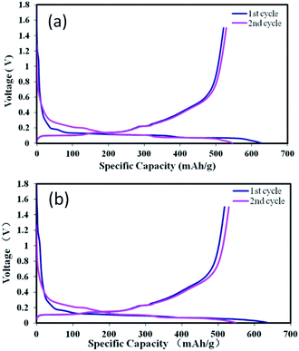
Coin cells were applied to investigate the influence of two binders upon the electrochemical performance. The galvanostatic charge and discharge curves of the anodes prepared from the two binders are shown in Fig. 3. The charge and discharge curves appear to be similar. There is a plateau around 1.05 V in the first discharge process, which is ascribed to the formation of the SEI film. It can be easily recognized by comparing with the cyclic voltammetry (CV) curve (Fig. 5a). As shown, the plateau with the PPA binder is obviously longer than that with the SBR binder, demonstrating the larger lithium consumption and irreversible capacity loss. Two electrodes presented a plateau from 0.4 V to 0.2 V in the first discharge process, which corresponds to the formation of Li2O and inactive lithium silicates (mainly Li4SiO4).9,31,33 The plateau around 0.4 V is referred to the delithiation process of lithium silicide. The first charge–discharge curves show that the anode material has a high irreversible capacity loss. The results from the first two cycles are shown in Table 1. The first coulombic efficiency and discharge specific capacity of SiOx–graphite were 83.6% and 626.5 mA h g−1 using SBR as the binder, while 81.2% and 636.1 mA h g−1 when using PAA as the binder, suggesting that the results of two parallel experiments were similar. Compared with the SBR binder, the carboxylic acid functional groups of the PAA binder has strong hydrophilicity. According to the literature,34,35 the carboxylic acid functional groups of PAA are reactive towards the electrolyte, causing the decomposition of LiPF6 and dissolution of SiOx during the electrode wetting process and leading to the larger lithium consumption and higher irreversible capacity loss (assigned to the formation of the SEI film). The improved 2nd charge capacity is speculated due to the formation of Li2O increasing the electron conductivity to improve the lithium insertion and extraction. Another reason is the formation of the stable SEI film and the irreversible reaction being substantially less than that of the 1st discharge and charge process.
| 1 dis. (mA h g−1) | 1 charge (mA h g−1) | 1st CE (%) | 2 dis. (mA h g−1) | 2 charge (mA h g−1) | |
|---|---|---|---|---|---|
| SBR-1 | 624.9 | 523.7 | 83.8 | 543.9 | 526.0 |
| SBR-2 | 626.5 | 523.9 | 83.6 | 546.4 | 529.1 |
| PAA-1 | 636.1 | 516.3 | 81.2 | 547.2 | 528.7 |
| PAA-2 | 639.4 | 517.1 | 80.8 | 544.2 | 524.9 |
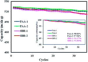
In order to demonstrate the difference in effectiveness between the two binders, the above composite electrodes were cycled at a current rate of 0.2C, and the long term cyclability is shown in Fig. 4. The SiOx–graphite electrode with the PAA binder exhibited much better cycle performance with a specific capacity of ∼523 mA h g−1 after the 36th cycle, which was higher than that of the composite electrode with the SBR binder (∼512 mA h g−1). The cells using the PAA binder retained ∼98% of the initial specific capacity, compared to ∼96% for that with the SBR binder. Furthermore, it was found that the capacity loss of the cells with the SBR binder significantly increased after the 28th cycle.
The cyclic voltammograms of coin cells at a scan rate of 0.5 mV s−1 are presented in Fig. 5a. The two batteries showed the peak around 1.05 V, which disappeared in the following two cycles, corresponding to the formation of the SEI film associated with the decomposition of the electrolyte additive FEC and VC.36–38 It was also verified by the first charge and discharge curves (Fig. 3). The weak peak from 0.5 V to 0.2 V mainly corresponds to the lithiation of SiOx into Li2O and electrochemically inactive lithium silicates, primarily Li4SiO4.9,39–42 Although the scan rate of 0.5 mV s−1 was very fast (the scan rate of 0.1–0.2 mV s−1 is often used by numerous researchers20,36), the peak position was similar and almost no obvious deviation was observed in the first three cycles. It may be ascribed to the 2% VGCF in the anode electrode to enhance the electronic connectivity of particles. The EIS spectra of the two composite electrodes at pristine and first Li lithiated (discharge) state are shown in Fig. 5b. As known, from the high frequency to the medium frequency, one or two semicircles are assigned to the electrolyte–electrode interface resistance (RSEI) and charge transfer resistance (Rct). It was seen that all of the Ohm resistance was almost the similar in the ultra-high frequency. However, the total of RSEI + Rct with the PPA binder is larger than that with the SBR binder at pristine and full lithiated states. Also, it was also obvious that the resistance change with the PAA binder from pristine to the lithiated state was significantly larger than that with the SBR binder.
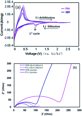 | ||
| Fig. 5 (a) CV and (b) EIS of the SiOx–graphite anode coin cells with SBR and PAA binders at pristine and first lithiated states. | ||
The rate performance of the anode electrodes in half cells with SBR and PAA binders is exhibited in Fig. 6a. The similar specific capacities of the two cells were achieved at small current (0.1–0.5C). After the current shifted to 1C, however, the cell using the SBR binder obtained higher capacity. As known, SBR is a type of an emulsion binder, which is dotted on the active material surface (Fig. 6b). Compared with the solution binder PAA, the SBR binder can form more Li+ transport channels for ionic conduction due to the low degree of coating on the surface of the active material. Based on the results from EIS, rate performance and the mechanism of the SBR emulsion binder, the SBR binder exhibited to be more conducive to the transfer of electrons and ions on the electrodes.
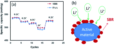 | ||
| Fig. 6 (a) Rate performance of coin cells with SBR and PAA binders. The current rates at 0.1–1C (b) action mechanism of the SBR binder. | ||
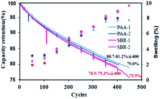
To further investigate the influence of SBR and PAA binders on the performance of the full battery, 423480 pouch cells with the LCO cathode and the SiOx–graphite anode were assembled to evaluate the battery cycle and swelling and electrode manufacturing performance. The cycle performance and cell swelling are presented at rate of 0.7C charge and 0.5C discharge in the range of 2.75–4.35 V in Fig. 7. The ratio of swelling was calculated as follows: (Tn: the thickness after nth cycling, T0: the thickness before cycling).
The results indicate that the trend of cycle performance using SBR and PAA was similar at the beginning of the cycle. However, the use of the PPA binder showed much better cyclic stability and lower volume swelling during the cycling. After 400 cycles, the capacity retentions of the cells using SBR and PAA binders were ∼79% and ∼81%, respectively. The swelling of cells with the SBR binder was ∼8.5%, while it was ∼7.5% with the PAA binder. With ongoing cycling, the cycle performance with the SBR binder decreased rapidly to 75.9% at the 450th cycle. Also, the swelling with SBR increased rapidly to ∼9.6%, while the capacity retentions and swelling of the cell using the PPA binder were 79.0% and ∼7.5%, respectively. From dissection batteries (SBR-1 and PAA-2) after 400 cycles, more dead zone was found (the part marked in red circle) on the anode electrode surface using SBR as the binder (Fig. 8a). Fig. 8b–d present the surface morphology of the electrode dead zone. The cracks of 1–2 μm are observed clearly after cycling (Fig. 8b and d). Fig. 8c shows the lithium deposition on the dead zone to block the electrode surface, which explains their relatively rapid capacity fading. It is inferred that the excessive volume expansion during the cycles caused a chain of side reactions, leading to the unstable SEI and the poor cycle performance. Table S2† lists the changes of the internal resistance (IR) and anode electrode thickness before and after the cycling. As shown, the IR and swelling of the electrode of the batteries using the PAA binder were lower than those using the SBR binder after cycling.
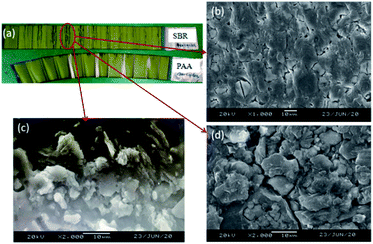 | ||
| Fig. 8 (a) Anode electrode morphologies after 400th cycles; (b–d) SEM images of the part marked in the red circle of electrode using the SBR binder. | ||
However, during the electrode manufacturing process, it was found the electrode using PAA as the binder is brittle22 and easy to crack (Fig. S3†). One of the possible reasons is the high glass transition temperature (Tg) (106 °C). Tg is the lowest temperature, which the molecular chain of the polymer can move. The higher the Tg, the less the flexibility of the molecular chain. The other possible reason is attributed to the carboxyl groups, which can form strong hydrogen bonds to obtain undesirable flexibility.43
4. Conclusions and prospects
In this study, we investigated the influence of two binders on the performances of the 15% SiOx–graphite composite anode with half cells (coin) and high voltage pouch battery (423480 type pouch cells). The results showed the similar adhesion of the two anode electrodes using the PAA and SBR binders under the same conditions. The 1st coulombic efficiency and 1st charge specific capacity of the composite electrode using the SBR binder were higher than those of the electrode using the PAA binder. The SBR binder showed to be more conducive to the transfer of electrons and ions on the electrodes and obtained better capacity at 1C current. In practical applications (high voltage pouch battery), the batteries with the PAA binder show better cycle performance and lower swelling.Nevertheless, when using PPA as the binder, the electrode was found relatively brittle to crack, which hinders subsequent mass manufacturing ability. For boosting the electrode manufacturing capacity and improved electrochemical performance using PAA as the binder in the mass production, we will further investigate how to improve the 1st coulombic efficiency, electrode flexibility and electrochemical performance.
Conflicts of interest
There are no conflicts to declare.Acknowledgements
All the authors are grateful to Tianjin Lishen Company for assembling the electrode and pouch cell. This research was supported by the National Natural Science Foundation of China (51806186).Notes and references
- J. B. Goodenough and K. Park, J. Am. Chem. Soc., 2013, 135, 1167–1176 CrossRef CAS.
- K. Amine, R. Kanno and Y. Tzeng, MRS Bull., 2014, 39, 395–401 CrossRef CAS.
- Y. Xia, G. Wang, X. Zhang, B. Wang and H. Wang, Electrochim. Acta, 2016, 220, 643–653 CrossRef CAS.
- S. J. Kim, S. H. Moon, M. C. Kim, J. Y. So, S. B. Han, D. H. Kwak, W. G. Bae and K. W. Park, J. Appl. Electrochem., 2018, 48, 1057–1068 CrossRef CAS.
- T. Wang, X. T. Guo, H. Y. Duan, C. Y. Chen and H. Pang, Chin. Chem. Lett., 2020, 31, 654–666 CrossRef CAS.
- B. Liang, Y. Liu and Y. Xu, J. Power Sources, 2014, 267, 469–490 CrossRef CAS.
- M. N. Obrovac and L. Christensen, Electrochem. Solid-State Lett., 2004, 7, A93–A96 CrossRef CAS.
- Z. H. Liu, Q. Yu, Y. L. Zhao, R. H. He, M. Xu, S. H. Feng, S. D. Li, L. Zhou and L. Q. Mai, Chem. Soc. Rev., 2019, 48, 285–309 RSC.
- T. Chen, J. Wu, Q. L. Zhang and X. Su, J. Power Sources, 2017, 363, 126–144 CrossRef CAS.
- U. Farooq, J. H. Choi, S. A. Pervez, A. Yaqub, D. H. Kim, Y. J. Lee, M. Saleem and C. H. Doh, Mater. Lett., 2014, 136, 254–257 CrossRef CAS.
- S. Komaba, N. Yabuuchi, T. Ozeki, Z. J. Han, K. Shimomura, H. Yui, Y. Katayamma and T. Miura, J. Phys. Chem. C, 2012, 116, 1380–1389 CrossRef CAS.
- H. Buqa, M. Holzapfel, F. Krumeich, C. Veit and P. Novak, J. Power Sources, 2006, 161, 617–622 CrossRef CAS.
- C. Chen, S. H. Lee, M. Cho, J. Kim and Y. Lee, ACS Appl. Mater. Interfaces, 2016, 8, 2658–2665 CrossRef CAS.
- B. Koo, H. Kim, Y. Cho, K. T. Lee, N. S. Choi and J. Cho, Angew. Chem., Int. Ed., 2012, 51, 8762–8767 CrossRef CAS.
- X. H. Yu, H. Y. Yang, H. W. Meng, Y. L. Sun, J. Zheng, D. Q. Ma and X. H. Xu, ACS Appl. Mater. Interfaces, 2015, 7, 15961–15967 CrossRef CAS.
- A. Magasinski, B. Zdyrko, I. Kovalenko, B. Hertzberg, R. Burtovyy, C. F. Huebner, T. F. Fuller, I. Luzinov and G. Yushin, ACS Appl. Mater. Interfaces, 2010, 2, 3004–3010 CrossRef CAS.
- L. Y. Shen, L. Shen, Z. X. Wang and L. Q. Chen, ChemSusChem, 2014, 7, 1951–1956 CrossRef CAS.
- J. S. Kim, W. Choi, K. Y. Cho, D. Byun, J. Lim and J. K. Lee, J. Power Sources, 2013, 244, 521–526 CrossRef CAS.
- X. J. Feng, J. Yang, X. L. Yu, J. L. Wang and Y. N. Nuli, J. Solid State Electrochem., 2013, 17, 2461–2469 CrossRef CAS.
- T. L. Zhao, Y. Meng, H. S. Yin, K. J. Guo, R. X. Ji, G. L. Zhang and Y. X. Zhang, Chem. Phys. Lett., 2020, 742, 137145 CrossRef CAS.
- Y. M. Sun, J. Lopez, H. W. Lee, N. Liu, G. Y. Zheng, C. L. Wu, J. Sun, W. Liu, J. W. Chung, Z. N. Bao and Y. Cui, Adv. Mater., 2016, 28, 2455–2461 CrossRef CAS.
- Z. X. Xu, J. Yang, T. Zhang, Y. N. Nuli, J. l. Wang and S. I. Hirano, Joule, 2018, 2, 950–961 CrossRef CAS.
- H. Zhao, A. L. Du, M. Ling, V. Battaglia and G. Liu, Electrochim. Acta, 2016, 209, 159–162 CrossRef CAS.
- P. Chen, W. L. Huang, H. T. Liu, Z. J. Cao, Y. Yu, Y. S. Liu and Z. Q. Shan, J. Mater. Sci., 2019, 54, 8941–8954 CrossRef CAS.
- K. Lee and T. H. Kim, Electrochim. Acta, 2018, 283, 260–268 CrossRef CAS.
- J. Song, M. Zhou, R. Yi, T. Xu, M. L. Gordin, D. Tang, Z. Yu, M. Regula and D. Wang, Adv. Funct. Mater., 2014, 24, 5904–5910 CrossRef CAS.
- H. K. Park, B. S. Kong and E. S. Oh, Electrochem. Commun., 2011, 13, 1051–1053 CrossRef CAS.
- Z. Y. Wu, L. Deng, J. T. Li, Q. S. Huang, Y. Q. Lu, J. Liu, T. Zhang, L. Huang and S. G. Sun, Electrochim. Acta, 2017, 245, 371–378 CrossRef CAS.
- J. S. Bridel, T. Azaïs, M. Morcrette, J. M. Tarascon and D. Larcher, Chem. Mater., 2010, 22(3), 1229–1241 CrossRef CAS.
- S. Flandrois, A. Fevrier, P. Biensan and B. Simon, US 5554462, 1996 Search PubMed.
- Q. Si, K. Hanai, T. Ichikawa, M. B. Phillipps, A. Hirano, N. Imanishi, O. Yamamoto and Y. Takeda, J. Power Sources, 2011, 196, 9774–9779 CrossRef CAS.
- J. Yang, Y. Takeda, N. Imanishi, C. Capiglia, J. X. Xie and O. Yamamoto, Solid State Ionics, 2002, 152–153, 125–129 CrossRef CAS.
- Y. Yamada, Y. Iriyama, T. Abe and Z. Ogumi, J. Electrochem. Soc., 2010, 157(1), A26–A30 CrossRef CAS.
- C. C. Nguyen, T. Yoon, D. M. Seo, P. Guduru and B. L. Lucht, ACS Appl. Mater. Interfaces, 2016, 8(19), 12211–12220 CrossRef CAS.
- T. Wohrle, P. R. Raimann, M. Winter, C. Wurm, N. S. Hochgatterer, S. Koller and M. R. Schweiger, Electrochem. Solid-State Lett., 2008, 11(5), A76–A80 CrossRef.
- T. Chen, J. Z. Hu, L. Zhang, J. Pan, Y. Y. Liu and Y. T. Cheng, J. Power Sources, 2017, 362, 236–242 CrossRef CAS.
- H. Ota, Y. Sakata, A. Inoue and S. Yamaguchi, J. Electrochem. Soc., 2004, 151(10), A1659–A1669 CrossRef CAS.
- D. Aurbach, K. Gamolsky, B. Markovsky, Y. Gofer and U. Heider, Electrochim. Acta, 2002, 47, 1423–1439 CrossRef CAS.
- M. Miyachi, H. Yamamoto, H. Kawai, T. Ohta and M. Shirakata, J. Electrochem. Soc., 2005, 152, A2089–A2091 CrossRef CAS.
- Y. Nagao, H. Sakaguchi, H. Honda, T. Fukunaga and T. Esaka, J. Electrochem. Soc., 2004, 151, A1572–A1575 CrossRef CAS.
- Y. Yamada, Y. Iriyama, T. Abe and Z. Ogumi, J. Electrochem. Soc., 2010, 157(1), A26–A30 CrossRef CAS.
- M. Miyachi, H. Yamamoto and H. Kawai, J. Electrochem. Soc., 2007, 154, A376–A380 CrossRef CAS.
- K. Feng, M. Li, W. W. Liu, A. G. Kashkooli, X. C. Xiao, M. Cai and Z. W. Chen, Small, 2018, 14, 1702737 CrossRef.
Footnote |
| † Electronic supplementary information (ESI) available: Including Tables S1 and S2 and Fig. S1–S3. See DOI: 10.1039/d0ra10283k |
| This journal is © The Royal Society of Chemistry 2021 |

