 Open Access Article
Piezoelectric property comparison of two-dimensional ZnO nanostructures for energy harvesting devices
Ang Yang a,
Yu Qiu
 *ac,
Dechao Yangb,
Kehong Lina and
Shiying Guoa
aSchool of Physics, Dalian University of Technology, Dalian 116024, People's Republic of China. E-mail: yuqiu@dlut.edu.cn
bSchool of Intelligence and Electronic Engineering, Dalian Neusoft University of Information, Dalian, 116024, People's Republic of China
cThe Key Laboratory for Micro/Nano Technology and System of Liaoning Province, Dalian University of Technology, Dalian 116024, China
First published on 18th January 2021
Abstract
In this paper, experimental and theoretical studies of the piezoelectric effect of two-dimensional ZnO nanostructures, including straight nanosheets (SNSs) and curved nanosheets (CNSs) are conducted. The results show that the CNSs have a great advantage in piezoelectric property over the SNSs; the maximum output current of the NG based on CNSs was measured to be about 260 nA, much higher than that generated by SNSs. For comparatively analyzing the working mechanics of both NGs, the piezopotential distribution of both CNS and SNS structures was studied using the finite element method. The simulation result that the piezopotential generated by CNSs is always much larger than that generated by SNSs in the case of lateral bending, has more advantages for piezoelectric NGs than the SNSs. This work may provide guidance for structural optimization of piezoelectric nanogenerators and designing high-performance self-powered strain sensors.
1. Introduction
With the rapid development of science and technology, more and more electronic devices are moving towards miniaturization and portability.1 Nowadays, multiple types of micro/nano robots and detectors which allow in situ, real-time safety monitoring and precise measurement, have been widely applied in many fields including national defense, energy, chemical engineering and electrical power, and the medical industry.2,3 While such micro/nano devices still need an external power source, at present, there exists a lot of inconvenience in charging or changing batteries for electronic devices, owing to their short battery life, environmental pollution problems and so on. Therefore, providing continuous and self-powered electric energy has become a new target for scientists. As we all know, there is a lot of green renewable energy available in the environment including solar energy, wind energy, nuclear energy, heat energy, and mechanical energy.4–6 Among them, mechanical energy is one of the most abundant and accessible energy resources in our daily life,7 for example body movement, vibrations, acoustic/ultrasonic waves and so on.Since Wang and Song's pioneering work on the first nanogenerator (NG) prototype using ZnO piezoelectric nanowires (NWs) for converting mechanical energy into electricity,8 NGs based on piezoelectric effect have emerged as one of the most promising approach to harvest ambient mechanical energies.9–12 Among other piezoelectric materials,11,13–16 ZnO with the direct wide band gap of 3.37 eV and large exciton binding energy of 60 meV, has aroused extensive research interests because of its excellent piezoelectric property as well as excellent electron transport property.17–19 Recently, various approaches have been explored to manufacture piezoelectric NGs based on various ZnO nanostructures, such as ZnO nanowires, and nanotubes, nanosheets, nanotrees, and so on.8,20–22 Especially, the emerging 2D nanostructures have many attractive properties such as high surface-to-volume ratio and good mechanical durability for applications in energy conversion and storage devices, etc.23–26 In recent years, our group have presented DC power generation based on 2D ZnO nanosheets by a two-step low temperature growth method, and different 2D nanosheets (such as nanosheets, nanowalls, and ultra-thin nanosheets) were also compared and analyzed.24 Our study shows that the appropriately tuning the morphology of the ZnO nanosheets is an effective way to increase the piezoelectric output performance.
Inspired by this work, in this paper we have developed a low-temperature method to grow ZnO nanogrids on aluminum foil substrate which comprises the curved nanosheets (CNSs), and furthermore, comparative research between common straight nanosheets (SNSs) and the CNSs are also conducted in our experiment experimentally and theoretically.
2. Experimental procedure
2.1 Hydrothermal growth of ZnO CNSs
We used a two-step hydrothermal method to grow the SNSs on ITO substrate, which have been demonstrated in our previous report.24 Here, we mainly focus on the one-step hydrothermal method of ZnO CNSs grown on aluminum foil substrate. The experiment steps are as follows: first of all, the aluminum substrate (0.8 × 0.8 cm2) was cleaned by acetone, ethanol and deionized water in turn. Then a 15–20 nm thick ZnO seed layer was deposited on the aluminum substrate by radio frequency magnetron sputtering, which was carried out in an argon atmosphere of 3.5 Pa at room temperature. The precursor solution containing 30 mmol L−1 1![[thin space (1/6-em)]](https://www.rsc.org/images/entities/char_2009.gif) :
:![[thin space (1/6-em)]](https://www.rsc.org/images/entities/char_2009.gif) 1 ratio of zinc acetate dehydrates [Zn(AC)2] and hexamethylenetetramine (HMTA) was prepared for ZnO CNSs, which were grown by soaking the seeded substrate in the solution at 95 °C for 3 hours. When the reaction was completed, the as-grown substrate was removed, rinsed with deionized water and dried.
1 ratio of zinc acetate dehydrates [Zn(AC)2] and hexamethylenetetramine (HMTA) was prepared for ZnO CNSs, which were grown by soaking the seeded substrate in the solution at 95 °C for 3 hours. When the reaction was completed, the as-grown substrate was removed, rinsed with deionized water and dried.
2.2 Fabrication of ZnO nanogenerators device based on CNSs
We deposited a 100 nm thick Au layer on another aluminum foil substrate as the top electrode by using a thermal evaporator. After covering the surface of CNSs coated aluminum foil substrate by using the top electrode, two flexible copper wires were connected to them by silver paste for electrical testing. At last, the whole devices were packaged with a thin layer of poly-(dimethylsiloxane) (PDMS), then the piezoelectric CNSs based NG was formed. For comparison, we also fabricated a SNS based NG with the similar fabrication process.242.3 Characterization and measurement
The surface morphologies of as-prepared ZnO CNSs and SNSs were both characterized by Scanning Electron Microscopy (SEM; FEI Nova NanoSEM). We utilized energy-dispersive spectroscopy (EDS) to confirm the content of the CNSs. The crystal structures were analyzed by using X-ray diffraction (XRD). And the piezoelectric output currents generated from the CNSs-based NG were studied using a Keithley 4200 semiconductor characterization system.3. Results and discussion
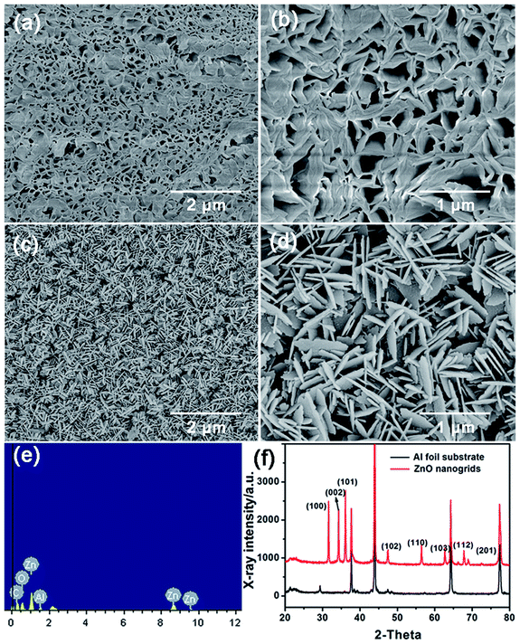
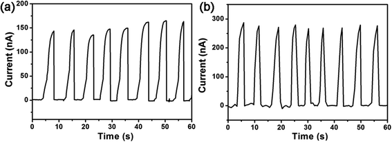
Fig. 1(a–d) demonstrates the SEM images of as-prepared CNSs and SNSs under different magnifications. We can see it clearly that CNSs look like nanogrids consisting of many curved nanosheets while SNSs are straight and interwoven. And they were both densely grown on the substrates. The arc length and thickness for the CNSs are about 1–2 μm and 50–100 nm in size. The average length of SNSs is 0.5–1 μm with a thickness in the range of 50–80 nm. The energy-dispersive spectrum (EDS) was also characterized for CNSs, as shown in Fig. 1(e), from which we can find that only four elements: Zn, Al, O and C can be observed from the spectrum. To characterize the crystal structure of CNSs, XRD pattern of the CNSs on Al foil substrate was investigated in Fig. 1(f). From Fig. 1(f), we can see that the intensity of (100) and (101) peak are higher than that of (002) peak, indicating that not all ZnO grew along the c-axis, which is related to the formation of the 2D lamellar structure. This result is in good agreement with the previous analysis.27For measuring the electric output performance generated from both NGs based on SNSs and CNSs, a manually applied pressure was periodically introduced to deform the device with a specially designed measuring setup,28 so that the NGs could experience a cycling pressing-releasing process. The measuring setup is consisted of a fixation, a platform, and a screw to apply a certain amount vertical force along the z-axis on a thin nanofilm. When the devices were pressed and released repeatedly, the DC-type current outputs were observed. Fig. 2 illustrate the current output signal of the as-fabricated NGs, when we press and release the NGs by rotating the screw at half circle (∼1 kgf) and releasing the screw. We can discover that both NGs generated DC type current signals. And the amplitude of signal fluctuates were about 150 and 260 nA, respectively. Since both of our nanofilms have an area of 0.8 × 0.8 cm2, so here the comparison of current is reasonable when approximately considering the same density of the two nanosheets. The time intervals of recovery time artificially controlled are relatively short, which means that both NGs have high sensitivity.
4. Numerically calculation
For better understanding the working mechanics of the as-fabricated NGs, the numerical calculation was carried out by the finite element method (FEM, COMSOL) for comparatively analyzing the piezopotential distribution of both CNS and SNS structures. The piezopotential of a fully coupled electro-mechanical system of nanostructure is calculated from the piezo-electric coupled equations.17,22 For simplicity of the calculation, the CNSs are assumed to be intrinsic, which stand vertically on the substrate and the bottom of each CNSs is fixed and electrically grounded. The CNSs are laterally bent or vertically compressed by a force which is uniformly applied at the entire top surface. The magnitude of the force is 1 × 10⁻⁶ N and the piezopotential is calculated along the vertical axis (c-axis) at the top of the CNSs. Except for the degree of bending, the SNSs are the same as the CNSs in every respect. The material's constants of ZnO are the elastic constants: c11 = 209.7 GPa, c12 = 121.1 GPa, c13 = 105.4 GPa, c33 = 211.2 GPa, c44 = 42.4 GPa, c55 = 42.4 GPa; piezoelectric constants e15 = −0.48 C m−2, e31 = −0.57 C m−2, e33 = 1.32 C m−2; relative dielectric constants k⊥ = 8.54, k‖ = 10.2, respectively.4.1 Vertical compression
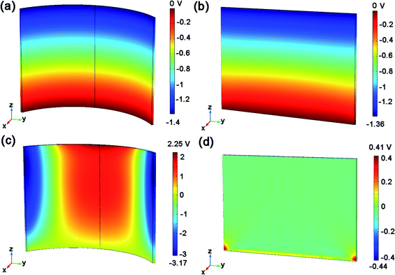
The calculated piezopotential distributions in the compressed CNSs and SNSs are revealed in Fig. 3(a) and (b). When a force is applied along −z axis on the top surface of CNSs and SNSs, the negative potential and positive potential are created along the top and bottom sides of both NSs, respectively. The maximum piezopotential of the CNSs (−1.4 V) is almost the same as that of the SNSs (−1.36 V). It is not hard to understand that both CNSs and SNSs can be regarded as the permutation and combination of nanowires in case of vertical compression. Thus, the piezopotentials generated from both nanostructures with the same size are almost the same.4.2 Lateral bending
In our model, we define the arc length of the CNSs as its length and the height is along the z-axis. The length, height, thickness for the CNSs as well as the SNSs, equals to 3 μm × 2 μm × 50 nm in size. Besides, the arc length of the CNSs corresponds to a central angle θ of 108 degrees, which represents how much the CNSs bends. The above parameters are the initial parameters of the model, and all subsequent curves are plotted by changing one variable while keeping the others constant. Φ is the angle between the direction of transverse force and the positive x axis. Fig. 3(c) and (d) illustrate the electric potential distributions of the CNSs and the SNSs when the force is along x axis, respectively. For case of lateral bending, the CNSs will have a negative piezoelectric potential on both sides and a positive piezoelectric potential in the middle which will result in a piezoelectric potential and form an electric current in the external circuit when the top electrode contacts negative potential. Because the structure of the CNSs is symmetrical on both sides, the potential on both sides is also symmetrical. It is not difficult to imagine that when a lateral force is applied to the upper surface of the CNSs, both sides of the CNSs are compressed and the middle tends to be stretched because of the unique curved structure, which leads to the special potential distribution. However, for the SNSs, we can see that the piezoelectric potential presents a similar point-like distribution as shown in Fig. 3(d). The extreme value of negative piezopotential of SNSs (−0.44 V) is much smaller than that (−3.17 V) of CNSs.In order to further study the effect of various factors on the piezoelectric potential distribution, the dependence of piezoelectric potential on the thickness, length, height, the magnitude and orientation of force, and bending degree are, respectively, calculated.
4.3 Effect of geometric size on piezopotential
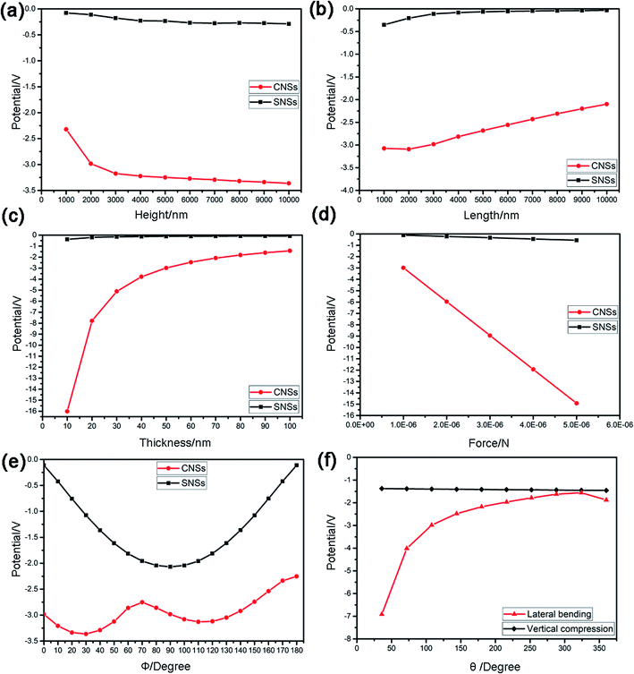
Fig. 4 shows the piezopotentials on the upper surface of CNSs and SNSs in case of vertical compression as the functions of their height, length, and thickness, respectively. As described earlier, the effect of geometric size on the piezopotentials generated from both nanostructures is almost the same. From Fig. 4(a) we can see that the piezopotentials increase almost linearly with the increasing of the height, which satisfies the standard formula V = Fg33L/A of piezopotential generated from vertically compressed nanorods in previous report.29 While the piezopotential decreases nonlinearly with the increasing of the thickness and length shown in Fig. 4(b) and (c). It could be understood that as the thickness and length increase, the vertical force per unit area of the upper surface decreases, contributing to the decreased piezopotential. This is consistent with the previous interpretation that nanosheet can be regarded as the permutation and combination of nanowires in case of vertical compression.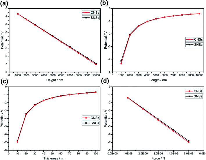 | ||
| Fig. 4 Piezopotentials as a function of height (a), length (b), thickness (c) and force (d) on the upper surface of CNSs and SNSs in case of vertical compression. | ||
Fig. 5(a–c) shows the piezopotential on the upper surface of CNSs and SNSs in case of lateral bending as the functions of their height, length and thickness. Because the piezopotential of SNSs in case of lateral bending is too small and the variation trend of the piezopotential is very gentle compared with that of CNSs, thus we pay more attention to the CNSs. The piezopotential of CNSs decreases nonlinearly with the increasing of the thickness and length and increases nonlinearly with the increasing of the height shown in Fig. 5(a–c). And when the thickness is very small, the piezopotential generated by the CNSs is very large. As mentioned above, due to the special curved structure, the lateral bending of CNSs results in strong local deformation rather than that of SNSs. It is reasonable that the greater the thickness and length, the more difficult it is for the CNSs to bend locally, while the greater the height, the greater the downward bending space on both sides of the CNSs. This implies that we can improve the piezopotential properties of CNSs by increasing the aspect ratio of it. In summary, there is little difference between the piezoelectric properties of the two nanostructures in vertical compression, while in case of lateral bending, the piezoelectric properties of the CNSs have a great advantage, which is conducive to the manufacture of high-performance piezoelectric nanogenerators.
4.4 Effect of magnitude of force on piezopotential
The piezopotential versus the magnitude of force is plotted in Fig. 4(d) and 5(d). It is obvious that under both vertical compression and lateral bending, the piezopotentials of both nanostructures are proportional to the magnitude of force and increase linearly as the force increases. This comes down to the following reasons: the force deforms the nanostructure and the greater the force, the greater the degree of deformation increase, resulting in the more severe the polarization degree and the higher the piezopotential. Most importantly, in case of lateral bending, the slope of the potential-force curve of CNSs is much larger than that of SNSs, which means that the CNSs is much more responsive to force than the SNSs. This will facilitate the manufacture of highly sensitive nanogenerators.4.5 Effect of force direction on piezopotential
Because the nanosheets are not isotropic, the direction of force would exert great influence on the magnitude and distribution of the piezopotential. To understand the anisotropic electricity generation based on the CNSs and SNSs, the piezopotential distributions in the bent CNSs and bent SNSs were calculated under a lateral force with different orientations. Φ is the angle between the direction of transverse force and the positive x axis. The piezopotential versus Φ is plotted in Fig. 5(e), from which, we can see that for CNSs, the potential–Φ curve exhibits a periodic oscillation and the piezopotential has two maxima, corresponding Φ of 30 degrees and 120 degrees. And the potential reaches its maximum when Φ is 30 degrees. While for the SNSs, the curve has only one peak, which is the maximum, corresponding Φ of 90 degrees. The curve may oscillates for the following reasons: on one hand, the anisotropic atom arrangement leads to anisotropic parameters such as elastic stiffness constant and dielectric constants; on the other hand, the geometric structure results in the different degree of deformation caused by different directions of force. It is obvious that even the minimum piezopotential of CNSs is greater than the maximum piezopotential of SNSs. This means that using CNSs will significantly enhance the capacity of electricity generation, compared with SNSs.4.6 Effect of bending degree on piezopotential
The CNSs grown in our experiments were of various shapes. Thus, the piezopotentials of CNSs with different bending degree in case of lateral bending and vertical compression are calculated in Fig. 5(f). θ is the central angle corresponding to the arc length of the CNSs. In case of vertical compression, θ has no influence on piezopotential. Just as mentioned earlier, CNSs can be regard as the permutation and combination of nanowires in case of vertical compression, so as long as the upper surface area is constant, the piezopotential is almost constant. From Fig. 5(f) we can see that, the piezopotential always decreases nonlinearly as θ increases in case of lateral bending until θ is 360 degrees, which means that the CNSs becomes a nanotube. However, strictly speaking, nanotubes were not present in our experiments. In other words, the piezopotential keeps decreasing before θ reaches exactly 360 degrees. Thus, the CNSs with low bending degree have higher piezoelectric properties, which may be because local deformation is more likely to occur under low bending degree. However, when θ is 0 degree, in which case it becomes a straight SNS, its piezopotential is minimal in case of lateral bending. Therefore, the unique curved structure of the CNSs greatly improves its piezoelectric properties in case of lateral bending.5. Conclusions
In summary, we have successfully grown straight nanosheets (SNSs) and curved nanosheets (CNSs) by a simply hydrothermal method. The electrical output signals of the NGs based on both structures were tested. The result shows that the maximum output current of the NG based on CNSs was measured to be about 260 nA, higher than that of NG based on SNSs (150 nA), which was sufficient to drive some micro/nano electronic devices. In order to explain the difference of output current caused by different structures, we used COMSOL software to simulate the piezopotential and displacement distribution of two nanosheets under the same conditions. The result shows that, in case of vertical compression, the piezopotentials generated by the two nanosheets have little difference in magnitude and distribution, while in the case of lateral bending, the piezopotential generated by CNSs is always much larger than that generated by SNSs. It can be seen from the displacement diagram that CNSs are prone to local strong deformation due to its unique curved structure in case of lateral bending. By comparing the same size CNSs and SNSs, we suggest that the CNSs have more advantage for designing high-performance piezo-nano/micro-devices. This investigation plays an important role in guiding the development of high-performance piezoelectric NGs and self-powered strain sensors.Conflicts of interest
There are no conflicts to declare.Acknowledgements
This work was supported by the Fundamental Research Funds for the Central Universities (DUT19LK28), National College Student Innovation and Entrepreneurship Training Program Support Project (No. 2020101411100011037), Natural Science Foundation of Liaoning Province (No. 2020-MS-316) and the NSFC (Project No. 61504018).References
- Z. L. Wang, G. Zhu, Y. Yang, S. Wang and C. Pan, Progress in nanogenerators for portable electronics, Mater. Today, 2012, 15(12), 532–543 CrossRef CAS.
- Y. Lin, P. Deng, Y. Nie, Y. Hu and X. Xue, Room-temperature self-powered ethanol sensing of a Pd/ZnO nanoarray nanogenerator driven by human finger movement, Nanoscale, 2014, 6(9), 4604–4610 RSC.
- W. Li, D. Torres, R. Díaz, Z. Wang, C. Wu, C. Wang, Z. L. Wang and N. Sepúlveda, Nanogenerator-based dual-functional and self-powered thin patch loudspeaker or microphone for flexible electronics, Nat. Commun., 2017, 8, 15310 CrossRef CAS.
- H. Sharon and K. S. Reddy, A review of solar energy driven desalination technologies, Renewable Sustainable Energy Rev., 2015, 41, 1080–1118 CrossRef CAS.
- B. Sahu Kumar, Wind energy developments and policies in China: a short review, Renewable Sustainable Energy Rev., 2018, 81(1), 1393–1405 CrossRef.
- S. R. Lichter and S. Rothman, Scientists' attitudes towards nuclear energy, Nature, 1983, 305(5930), 91–94 CrossRef.
- D. Yang, Y. Qiu, T. Wang, W. Song, Z. Wang, J. Xu, Q. Feng, Y. Zong and X. Sun, Growth of 3D branched ZnO nanowire for DC-type piezoelectric nanogenerators, J. Mater. Sci.: Mater. Electron., 2016, 27(7), 6708–6712 CrossRef CAS.
- L. Z. Wang, Piezoelectric Nanogenerators Based on Zinc Oxide Nanowire Arrays, Science, 2006, 312(5771), 242–246 CrossRef.
- M.-P. Lu, J. Song, M.-Y. Lu, M.-T. Chen, Y. Gao, L.-J. Chen and Z. L. Wang, Piezoelectric Nanogenerator Using p-Type ZnO Nanowire Arrays, Nano Lett., 2009, 9(3), 1223 CrossRef CAS.
- Y. Hu, L. Lin, Y. Zhang and Z. L. Wang, Replacing a Battery by a Nanogenerator with 20 V Output, Adv. Mater., 2012, 24(1), 110–114 CrossRef CAS.
- M. Riaz, J. Song, O. Nur, L. W. Zhong and M. Willander, Fiber/Fabric-Based Piezoelectric and Triboelectric Nanogenerators for Flexible/Stretchable and Wearable Electronics and Artificial Intelligence, Nano Energy, 2020, 56(4), 628–633 Search PubMed.
- C. Chang, V. H. Tran, J. Wang, Y.-K. Fuh and L. Lin, Direct-Write Piezoelectric Polymeric Nanogenerator with High Energy Conversion Efficiency, Nano Lett., 2010, 10(2), 726 CrossRef CAS.
- Y. F. Lin, J. Song, Y. Ding, S.-Y. Lu and Z. L. Wang, Piezoelectric nanogenerator using CdS nanowires, Appl. Phys. Lett., 2008, 92(2), 242 Search PubMed.
- J. H. Jung, M. Lee, J. I. Hong, Y. Ding, C. Y. Chen, L. J. Chou and Z. L. Wang, Lead-Free NaNbO3 Nanowires for a High Output Piezoelectric Nanogenerator, ACS Nano, 2011, 5(12), 10041–10046 CrossRef CAS.
- K. I. Park, S. Xu, Y. Liu, G. T. Hwang and K. J. Lee, Piezoelectric BaTiO3 Thin Film Nanogenerator on Plastic Substrates, Nano Lett., 2010, 10(12), 4939–4943 CrossRef CAS.
- K. I. Park, J. H. Son, G. T. Hwang, C. K. Jeong, J. Ryu, M. Koo, I. Choi, S. H. Lee, M. Byun and Z. L. Wang, Highly-efficient, flexible piezoelectric PZT thin film nanogenerator on plastic substrates, Adv. Mater., 2014, 26(16), 2450 CrossRef.
- B. Yin, Y. Qiu, H. Zhang, J. Lei, J. Ji, L. Li and L. Hu, Piezoelectric effect of one-dimensional gear-shaped ZnO microwires, Appl. Surf. Sci., 2014, 311, 621–625 CrossRef CAS.
- C. L. Hsu and K. C. Chen, Improving Piezoelectric Nanogenerator Comprises ZnO Nanowires by Bending the Flexible PET Substrate at Low Vibration Frequency, J. Phys. Chem. C, 2012, 116(16), 9351–9355 CrossRef CAS.
- J. Zhou, Y. Gu, P. Fei, W. Mai, Y. Gao, R. Yang, G. Bao and Z. L. Wang, Flexible Piezotronic Strain Sensor, Nano Lett., 2008, 8(9), 3035–3040 CrossRef CAS.
- Y. Lee, S. Kim, D. Kim, C. Lee and J. H. Lee, Direct-current flexible piezoelectric nanogenerators based on two-dimensional ZnO nanosheet, Appl. Surf. Sci., 2020, 509, 145328 CrossRef CAS.
- S. Stassi, V. Cauda, C. Ottone, A. Chiodoni, C. F. Pirri and G. Canavese, Flexible piezoelectric energy nanogenerator based on ZnO nanotubes hosted in a polycarbonate membrane, Nano Energy, 2015, 13, 474–481 CrossRef CAS.
- B. Yin, Y. Qiu, H. Zhang, J. Lei, Y. Chang, J. Ji, Y. Luo, Y. Zhao and L. Hu, Piezoelectric effect of 3-D ZnO nanotetrapods, RSC Adv., 2015, 5(15), 11469–11474 RSC.
- B. Kumar, K. Y. Lee, H. K. Park, S. J. Chae and S. W. Kim, Controlled growth of semiconducting nanowire, nanowall, and hybrid nanostructures on graphene for piezoelectric nanogenerators, ACS Nano, 2011, 5(5), 4197 CrossRef CAS.
- Q. Wang, D. Yang, Y. Qiu, X. Zhang, W. Song and L. Hu, Two-dimensional ZnO nanosheets grown on flexible ITO-PET substrate for self-powered energy-harvesting nanodevices, Appl. Phys. Lett., 2018, 112(6), 063906.1–063906.5 Search PubMed.
- M. K. Gupta, J. H. Lee, K. Y. Lee and S. W. Kim, Two-Dimensional Vanadium-Doped ZnO Nanosheet-Based Flexible Direct Current Nanogenerator, ACS Nano, 2013, 7(10), 8932–8939 CrossRef CAS.
- K. H. Kim, B. Kumar, K. Y. Lee, H. K. Park, J. H. Lee, H. H. Lee, H. Jun, D. Lee and S. W. Kim, Piezoelectric two-dimensional nanosheets/anionic layer heterojunction for efficient direct current power generation, Sci. Rep., 2013, 3, 2017 CrossRef.
- J. Chen, Y. Qiu, D. Yang, J. She and Z. Wang, Improved piezoelectric performance of two-dimensional ZnO nanodisks-based flexible nanogengerators via ZnO/Spiro-MeOTAD PN junction, J. Mater. Sci.: Mater. Electron., 2020, 31(9), 5584–5590 CrossRef CAS.
- J. Lei, B. Yin, Y. Qiu, H. Zhang, Y. Chang, Y. Luo, Y. Zhao, J. Ji and L. Hu, Flexible piezoelectric nanogenerator based on Cu2O–ZnO p–n junction for energy harvesting, RSC Adv., 2015, 5(73), 59458–59462 RSC.
- M.-Y. Choi, D. Choi, M.-J. Jin, I. Kim and S.-H. Kim, Mechanically Powered Transparent Flexible Charge-Generating Nanodevices with Piezoelectric ZnO Nanorods, Adv. Mater., 2009, 21(21), 2185–2189 CrossRef CAS.
| This journal is © The Royal Society of Chemistry 2021 |

