DOI:
10.1039/D0RA09753E
(Paper)
RSC Adv., 2021,
11, 3371-3379
Synthesis of Mn-MOFs loaded zinc phosphate composite for water-based acrylic coatings with durable anticorrosion performance on mild steel†
Received
17th November 2020
, Accepted 8th January 2021
First published on 15th January 2021
Abstract
A new metal–organic framework (MOF) compound [Mn2(2,2′-bca)2(H2O)2]n (Mn-MOFs) was successfully synthesized by solvothermal method, and Mn-MOFs@Zn material was prepared by loading zinc phosphate onto Mn-MOFs by ball milling, then Mn-MOFs@Zn was added to the water-based acrylic paint to prepare Mn-MOFs@Zn@acrylic coating. The AC impedance test results showed Mn-MOFs@Zn@acrylic coating has higher corrosion inhibition performance and stability to mild steel when compared with blank coating. The impedance modulus of the blank coating in the low frequency region decreased by 90%, and the Rct showed a trend of first increasing and then decreasing over time, the maximum Rct was only 303.8 Ω, which was only Mn-MOFs@Zn@acrylic coating one-seventh of the Rct value. The artificial scratch experiment showed that the Mn-MOFs@Zn@acrylic coating only slightly corrodes at the scratches, because Mn-MOFs@Zn material made the coating a self-repairing function and improved the durable anticorrosion performance of the acrylic coating.
1 Introduction
Organic coatings have been widely used for corrosion protection of metal substrates due to the barrier effect of organic coatings.1–5 However, the deterioration of the coating during its use leads to a decrease in its barrier properties. Adding various types of fillers and pigments to the coating is an important method to extend its service life.6–9 Zinc phosphate is a commonly used anti-corrosion pigment/filler used to improve the protective performance of organic coatings. A. C. Bastos added zinc phosphate as a pigment to the epoxy primer. Experiments proved that epoxy coatings with zinc phosphate added have better corrosion inhibition performance than pure epoxy coatings.10 A. Sakhri introduced zinc phosphate as a pigment into chlorinated rubber coatings. The experimental results showed that the introduction of zinc phosphate pigment significantly improved the corrosion inhibition performance of chlorinated rubber coatings on mild steel in salt solutions.11 However, the release of zinc ions and phosphate ions in the aqueous solution is insufficient due to the poor water solubility of zinc phosphate, and the damaged part of the coating cannot be effectively protected.12–15
Self-healing smart coatings are a new method to solve corrosion problems, which can provide appropriate responses to mechanical and chemical damage.16 The self-healing ability of polymer coatings is a way to make them smart, which can provide effective corrosion protection for metals without manual intervention. Changes in the external micro-environment (such as pH, magnetic field, electric field, temperature, etc.) or mechanical damage to the coating cause the micro-containers or nano-containers that store the corrosion inhibitor or self-healing agent to release the corrosion inhibitor or self-healing agent.17,18 When cracks appear in the coating, the corrosive medium spreads to the coating matrix along with the cracks. At this time, the container responds to environmental stimuli and releases corrosion inhibitors to repair the damaged area.19–22
Metal–organic framework materials (MOFs) are a class of inorganic–organic hybrid crystalline materials constructed by inorganic metal ions and organic ligands through coordination bonds, intermolecular forces, or hydrogen bonds. They have structural diversity, high porosity, high specific surface area, etc., so MOFs can be used as load materials.23,24 K. Y. Cao synthesized the cerium metal–organic framework (Ce-MOF) and used it as a nano container, added benzotriazole (BTA) with anti-corrosion properties, and finally wrapped Ce-MOF with tetraethyl orthosilicate (TEOS) to develop self-healing paint. Ce-MOF@TEOS composites show excellent dispersibility in epoxy coatings. More importantly, the resulting polymer coating exhibits effective self-healing function.25 H. W. Tian synthesized the corrosion inhibitor ATT, and combined the inhibitor with MOFs material ZIF-8. The experimental results proved that ATT@ZIF-8 showed better corrosion inhibition performance than simply adding ATT inhibitors.26 It can be seen that the MOFs material has good compatibility with the coating. Therefore, the zinc phosphate is loaded into the MOFs material and the composite material is used as the pigment of the coating, on the one hand, the solubility of the zinc phosphate in the coating can be improved, thereby improving the corrosion inhibition performance of zinc phosphate, and on the other hand, the zinc phosphate molecules are gradually released to realize the self-repairing performance of the coating.
In this paper, a quinoline dicarboxylic acid nano metal–organic frameworks [Mn2(2,2′-bca)2(H2O)2]n (Mn-MOFs) powder materials were prepared by solvothermal method, and then Mn-MOFs@Zn material was prepared by loading zinc phosphate onto Mn-MOFs by ball milling; finally Mn-MOFs@Zn was added to the water-based acrylic paint to prepare Mn-MOFs@Zn@acrylic coating, scanning electron microscopy and pH release test were used to study the morphology of Mn-MOFs@Zn material and the release process of zinc phosphate in Mn-MOFs@Zn material, and the corrosion resistance of Mn-MOFs@Zn@acrylic coating to mild steel was studied by electrochemical testing methods.
2 Experimental section
2.1 Materials
The composition of the mild steel specimens (weight%) was C 0.160%, Mn 0.530%, Si 0.300%, S 0.045%, P 0.015% and Fe 98.950%. 2,2′-Diquinoline-4,4′-dicarboxylic acid was purchased from Haohong Biomedical Technology Co., Ltd. (Shanghai, China), zinc phosphate, manganese acetate tetrahydrate, triethylamine, N,N-dimethyl formamide (DMF), sodium hydroxide, sodium chloride, zinc reagent, hydrochloric acid, zinc standard solution were purchased from Aladdin (China, Shanghai), absolute ethanol, acetone were purchased from Xilong Chemical Co., Ltd. (China, Guangdong), water-based acrylic was purchased from Yoshida Chemical Co., Ltd. (China, Guangdong).
2.2 Preparation of Mn-MOFs
Scheme 1 shows the synthetic route of Mn-MOFs material. 3 mmol (1.0350 g) 2,2′-bisquinoline-4,4′-dicarboxylic acid was dissolved in 10 mL DMF solution, placed in a 50 mL beaker, 20 mL of distilled water containing 6 mmol (1.4761 g) Mn(CH3COO)2·4H2O was added to the beaker, the solution was magnetically stirred at room temperature for 10 min, adjusted to pH = 6 with triethylamine, and continued stirred for 30 min; the mixed solution was transferred to a 50 mL reaction kettle with a polytetrafluoroethylene bottle, and heated to 120 °C in an oven for 6 h. After 6 h, the oven was closed and slowly cooled to room temperature, a large amount of yellow-brown powder was generated. The mixed solution was centrifuged, and then the solids were washed alternately with absolute ethanol and acetone, and dried in vacuum at 50 °C for 6 h to obtain 2.3761 g of powdered Mn-MOFs. The yield was 80.49% (based on Mn). The crystal structure of Mn-MOFs is shown in Fig. 1.
 |
| | Scheme 1 Synthetic route of Mn-MOFs. | |
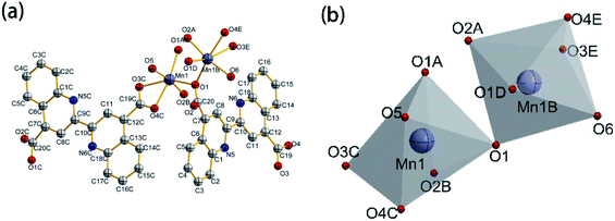 |
| | Fig. 1 Crystal structure of Mn-MOFs: (a) molecular structure ellipsoid; (b) coordination polyhedron (50% probability, the H atom in the figure has been ignored). | |
2.3 Preparation of Mn-MOFs@Zn
3.0 g of Mn-MOFs and 9.0 g of zinc phosphate were placed in a 50 mL beaker, then 45 g of distilled water and 4.5 g of SN-5040 dispersant were added in sequence, and magnetically stirred at room temperature for 1 h; the mixed solution was transferred to a ball mill for 400 rpm grinding speed for 1 h. After grinding, the mixed slurry was centrifuged, washed with absolute ethanol three times, and dried in a vacuum drying oven at 50 °C for 6 h to obtain Mn-MOFs@Zn.
2.4 Preparation of Mn-MOFs@Zn@acrylic coating
Scheme 2 shows the preparation route of Mn-MOFs@Zn@acrylic coating. 0.1035 g (0.5 wt%) Mn-MOFs@Zn were placed in 2 mL of distilled water, stirred and dispersed with a glass rod for 5 min, and then added to 20 mL of E0512 water-based acrylic varnish, ultrasonically dispersed for 15 min; the organic coating was applied to the pretreated mild steel surface with a brush, and the coating was cured at room temperature for 7 days, and manually scratched with a utility knife. The thickness of the coating is 50 μm.
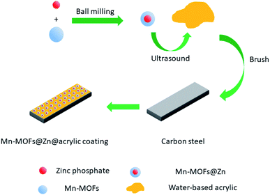 |
| | Scheme 2 Preparation route of Mn-MOFs@Zn@acrylic coating. | |
2.5 Characterization of materials
X'Pert3 Powder type multifunctional X-ray diffractometer (Cu target, λ = 1.54056 Å) was used to collect X-ray diffraction data of Mn-MOFs; field emission scanning electron microscope (Zeiss Sigma 300) was used to characterize the microstructure of Mn-MOFs and Mn-MOFs@Zn; the field emission scanning electron microscope (SU 5000) was used to observe the surface morphology of the coating and the dispersion of the Mn-MOFs@Zn in the coating.
2.6 pH-Responsiveness and its corrosion inhibitor release tracking test
Appropriate amount of Mn-MOFs@Zn was dispersed in 4 mL 3.5% NaCl solution with pH = 2, 5, 7, 9, 12, and sonicated for 2 min at room temperature, and the state of the suspension after sonication was recorded by a digital camera. This data was used to explore the pH responsiveness of Mn-MOFs@Zn. The content of zinc ions in the solution was tested by the method specified in the Chinese national standard GB/T 10656-2008. The specific content of the method was to use zinc reagent spectrophotometry under the conditions of pH 8.0 and 9.5(by measuring the absorbance A value corresponding to different zinc content m to establish a calibration curve, the linear equation is A = 7.6114m + 0.2338, R = 0.987) to determine the content of zinc ions in the solution at different times; draw a pH-responsive controllable release curve to track the release of zinc phosphate. The following formula was used to calculate the release rate (Q) of zinc phosphate:where, m1 and m2 are the total zinc phosphate loading in Mn-MOFs@Zn (mg) and the release amount of zinc phosphate in Mn-MOFs@Zn (mg), respectively.
2.7 Electrochemical testing of coatings
CHI760-E electrochemical workstation was used for electrochemical measurement. In this paper, a time gradient experiment was carried out. Since the polarization test would destroy the sample, it was not appropriate to conduct the polarization test. Instead, the AC impedance method was used to conduct the electrochemical test. A three-electrode system is adopted, in which the low carbon steel plate coated with Mn-MOFs@Zn@acrylic coating (with artificial scratches) is the working electrode (WE), the platinum wire electrode (with an area of 1 cm2) is the auxiliary electrode (CE), and the saturated calomel electrode (SCE) is the reference electrode (RE). WE was immersed in 3.5% NaCl corrosion solution for 2400 s until the system reached a steady state and the open circuit potential (EOCP) value was measured. After the equilibrium state EOCP is established, electrochemical impedance spectroscopy (EIS) measurements are performed. For electrochemical impedance spectroscopy (EIS) test, the initial potential is set to open circuit potential, the high frequency of the AC impedance spectroscopy test is set to 100![[thin space (1/6-em)]](https://www.rsc.org/images/entities/char_2009.gif) 000 Hz, the low frequency is set to 0.01 Hz, the amplitude is set to 0.005 V, and the sensitivity is set to automatically adjust the sensitivity. The electrochemical parameters of AC impedance spectroscopy are fitted by ZView impedance fitting software.
000 Hz, the low frequency is set to 0.01 Hz, the amplitude is set to 0.005 V, and the sensitivity is set to automatically adjust the sensitivity. The electrochemical parameters of AC impedance spectroscopy are fitted by ZView impedance fitting software.
3 Results and discussion
3.1 XRD analysis of Mn-MOFs
Fig. 2 is the PXRD pattern of Mn-MOFs. As shown in Fig. 2, line a is the diffraction peak tested in the experiment, and line b is the diffraction peak simulated by the mercury software. By comparing the experimentally tested diffraction peaks of polycrystalline powder samples with the simulated diffraction peaks of a single crystal, it can be seen that the positions of the peaks are basically the same, indicating that the powdered Mn-MOFs had been successfully synthesized. At the same time, the average grain size of the sample was calculated 48.8 nm by Jade 5.6 software, indicated that the solvothermal method can prepare nanomaterials with uniform particles.
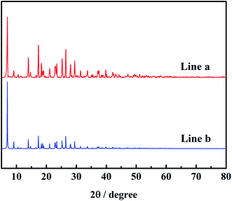 |
| | Fig. 2 The powder X-ray diffraction patterns of as-synthesized Mn-MOFs (a) and simulated Mn-MOFs (b). | |
3.2 Analysis of surface topography
Fig. 3 is the micro-topography of the material. As shown in Fig. 3(a), Mn-MOFs have a tubular structure, the nozzles are neat and not rough, and the lengths are different. The average diameter and length of Mn-MOFs calculated by ImageJ software are 98 nm and 113 nm, respectively; it can be seen from Fig. 3(b) that the Mn-MOFs@Zn have a needle-like structure, and the image shows that the needle-like particles of Mn-MOF loaded with zinc phosphate are stacked together to form a block structure. For materials with needle-like structures, it can be better cross-stacked to form a denser structure, which can better play the function of fillers and effectively fill the gaps formed by the acrylic coating during the curing process.
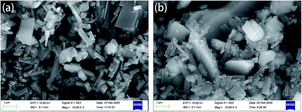 |
| | Fig. 3 Scanning electron micrograph of materials: (a) Mn-MOFs; (b) Mn-MOFs@Zn. | |
Fig. 4 is a scanning electron micrograph of the coating. From Fig. 4(a), it can be seen that the surface of the pure water-based acrylic coating without any fillers is flat and uniform; the surface of the Mn-MOFs@Zn@acrylic coating in Fig. 4(b) is flat, and Mn-MOFs@Zn is evenly distributed on the coating. In the layer, no agglomeration and micro-defects were observed, which indicates that Mn-MOFs@Zn has good compatibility with water-based acrylic resin at 0.5 (wt%) addition.
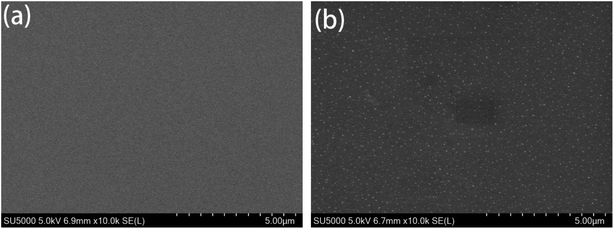 |
| | Fig. 4 Scanning electron micrograph of coatings: (a) pure water-based acrylic coating; (b) Mn-MOFs@Zn@acrylic coating. | |
3.3 Analysis of pH-responsiveness and its corrosion inhibitor release tracking
Fig. 5 and 6 are the suspension state diagram of Mn-MOFs@Zn at different pH and the controlled release curve diagram of zinc phosphate, respectively. It can be seen from Fig. 5 that at pH 2 and 12, the suspension solution is relatively clear, indicating that the Mn-MOFs@Zn disintegrates rapidly under strong acid or alkali conditions; the suspension is relatively turbid at pH 5 and 9, which indicates that Mn-MOFs@Zn is relatively stable under weak acid and weak alkali conditions, and the disintegration rate is relatively slow. It can be seen from Fig. 6 that under the conditions of pH = 8.5 and 9, the release rate of Mn-MOFs@Zn to zinc phosphate has basically the same trend as a whole. After 570 min, 38.6% of zinc phosphate was released from Mn-MOFs@Zn at pH = 8.5, and 42.1% of zinc phosphate was released from Mn-MOFs@Zn at pH = 9. All in all, Mn-MOFs@Zn can slowly release zinc phosphate in a weakly alkaline environment. Since the pH of actual seawater is weakly alkaline, this indicates that Mn-MOFs@Zn has great potential in inhibiting seawater corrosion.
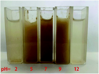 |
| | Fig. 5 State diagrams of suspensions of Mn-MOFs@Zn at different pH values (from left to right pH = 2, 5, 7, 9, 12). | |
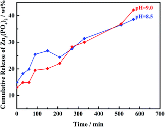 |
| | Fig. 6 Controlled release profiles of Mn-MOFs@Zn at different pH values. | |
3.4 Analysis of anti-corrosion performance of Mn-MOFs@Zn@acrylic coating
Fig. 7–9 are the Nyquist diagram, Bode diagram and phase angle diagram of the pure water-based acrylic coating and the Mn-MOFs@Zn@acrylic coating in 3.5% NaCl under different immersion times. In the AC impedance spectroscopy test, it is generally believed that the larger the radius of the capacitive reactance arc, the larger the impedance value of the sample, which can prevent charge transfer more effectively, and the corrosion resistance is stronger;27 the impedance mode at low frequency (0.01 Hz) can be used to explain the ability of the coating to inhibit the flow of the circuit between the anode and the cathode. The larger the impedance modulus is, the better the anti-corrosion performance of the coating will be.28 It can be seen from Fig. 7 that the capacitive arc radius of the pure water-based acrylic coating decreased sharply after being immersed for 24 h, and the capacitive arc radius of the Mn-MOFs@acrylic coating decreased slowly after being immersed for 48 h. The capacitive arc radius of the Mn-MOFs@Zn@acrylic coating increased with the increase of the immersion time, indicating that the zinc phosphate was successfully released and a new protective film had been formed on the scratches, which delays the further corrosion of mild steel.
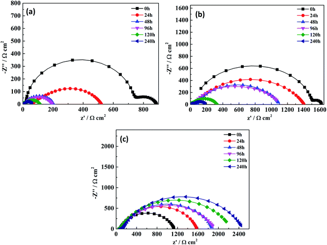 |
| | Fig. 7 Nyquist plots of two coatings at different immersion times: (a) the pure water-based acrylic coating; (b) the Mn-MOFs@acrylic coating; (c) the Mn-MOFs@Zn@acrylic coating. | |
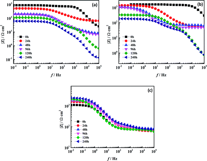 |
| | Fig. 8 Bode plots of two coatings at different immersion times: (a) the pure water-based acrylic coating; (b) the Mn-MOFs@acrylic coating; (c) the Mn-MOFs@Zn@acrylic coating. | |
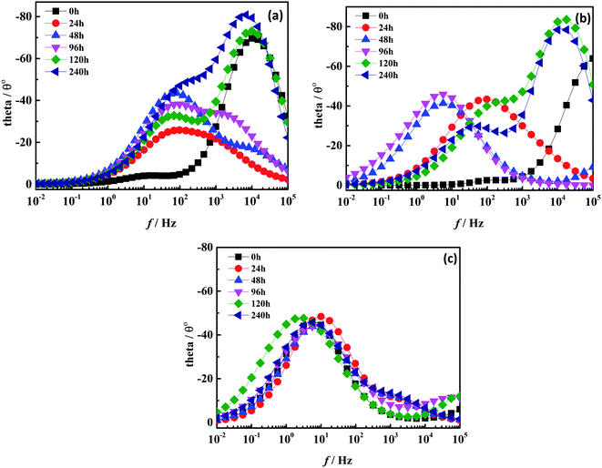 |
| | Fig. 9 Phase angle diagram of two coatings under different soaking times: (a) the pure water-based acrylic coating; (b) the Mn-MOFs@acrylic coating; (c) the Mn-MOFs@Zn@acrylic coating. | |
As shown in Fig. 8, after 240 h of immersion, the impedance modulus value of the pure water-based acrylic coating and Mn-MOFs@acrylic coating in the low frequency region decreased from 103 Ω cm2 to 102 Ω cm2, while the impedance modulus value of the Mn-MOFs@Zn@acrylic coating in the low frequency region still remained above 103 Ω cm2, indicating that the presence of zinc phosphate improves the corrosion resistance of the coating. It can be seen from Fig. 8 that in all immersion times, the curve has two time constants. The low-frequency time constant should be attributed to the corrosion process at the metal/coating interface, while the high-frequency time constant is attributed to the coating.29 Fig. 9(a) and (b) shows that as the immersion time increases, the time constant shifts to low frequency, which indicates that the protective performance of the coating on the low carbon steel is gradually lost, and the coating and the metal interface gradually occur corrosion. Fig. 9(c) shows that the time constant is concentrated in the mid-frequency region, indicating that the Mn-MOFs@Zn@acrylic coating has better corrosion protection performance than pure water-based acrylic coating. This is because the micro-domain pH change caused by corrosion triggers the release of zinc phosphate from the Mn-MOFs@Zn material, and the released zinc phosphate can be adsorbed on the corroded area and form a protective film to prevent corrosion.
The equivalent circuit diagram (Fig. 10) was used to fit the ac impedance spectrum test data to obtain electrochemical parameters, including coating resistance (Rc), charge transfer resistance (Rct), double layer capacitance response parameter Ccoat (Y1, n1) on electrolyte/mild steel substrate interface, and charge transfer capacitance response parameter Cdl (Y2, n2), the fitting data are listed in Table 1. In the equivalent circuit diagram, Rs is the solution resistance, Rc is the coating resistance, and Rct is the charge transfer resistance. Since the interface between the metal and the solution is not an ideal capacitor, constant phase components Ccoat and Cdl are introduced.
 |
| | Fig. 10 Equivalent circuit diagram for two coatings under different soaking times. | |
Table 1 EIS parameters for two coatings under different soaking times
| |
Time (h) |
Rc (Ω cm2) |
Ccoat |
Rct (Ω cm2) |
Cdl |
| Y1 (×10−6 Sn Ω−1 cm−2) |
n1 |
Y2 (×10−6 Sn Ω−1 cm−2) |
n2 |
| Pure water-based acrylic coating |
0 |
715.8 |
0.13 |
0.99 |
149.2 |
255.15 |
0.78 |
| 24 |
153.9 |
33.70 |
0.69 |
303.8 |
76.89 |
0.70 |
| 48 |
10.68 |
51.53 |
0.73 |
185.8 |
145.19 |
0.77 |
| 96 |
33.34 |
72.12 |
0.73 |
153.8 |
155.54 |
0.74 |
| 120 |
20.72 |
3.90 |
0.99 |
91.69 |
340.95 |
0.74 |
| 240 |
6.24 |
10.81 |
0.98 |
55.51 |
467.50 |
0.74 |
| Mn-MOFs@acrylic coating |
0 |
1475 |
0.02 |
0.91 |
106.1 |
11.98 |
0.99 |
| 24 |
102.9 |
20.08 |
0.72 |
1254 |
21.19 |
0.70 |
| 48 |
18.52 |
0.028 |
0.99 |
1035 |
287.91 |
0.72 |
| 96 |
709.6 |
346.72 |
0.78 |
355.4 |
2421.40 |
0.64 |
| 120 |
35.1 |
0.88 |
0.99 |
293.9 |
95.29 |
0.71 |
| 240 |
31.83 |
1.48 |
0.97 |
152.9 |
348.19 |
0.69 |
| Mn-MOFs@Zn@acrylic coating |
0 |
48.87 |
0.57 |
0.67 |
1061 |
207.69 |
0.80 |
| 24 |
40.35 |
21.16 |
0.79 |
1477 |
84.75 |
0.80 |
| 48 |
69.11 |
32.46 |
0.72 |
1741 |
94.53 |
0.77 |
| 96 |
48.8 |
9.18 |
0.62 |
1836 |
172.94 |
0.71 |
| 120 |
26.45 |
0.12 |
0.97 |
2181 |
338.15 |
0.72 |
| 240 |
75.88 |
33.98 |
0.70 |
2330 |
101.49 |
0.76 |
It can be seen from Table 1 that as the immersion time increases, the total polarization resistance Rt (Rt = Rc + Rct) of the pure water-based acrylic coating and the Mn-MOFs@acrylic coating decreases, while the Rt value of the Mn-MOFs@Zn@acrylic coating increases with it increases with the increase of time, which indicates that Mn-MOFs@Zn have fast pH-response characteristics and can repair the damaged parts of the metal in time to extend the protective effect of the coating on the mild steel.
Fig. 11 shows the surface morphology of the two coatings after being immersed in 3.5% NaCl for 240 h in the artificial scratch experiment. It can be seen from the figure that the scratched area of the pure water-based acrylic coating has obvious corrosion, and a large amount of reddish brown rust accumulates in the scratched area. The Mn-MOFs@Zn@acrylic coating has also been corroded to a certain extent after long-term immersion, but compared to the pure water-based acrylic coating, the Mn-MOFs@Zn@acrylic coating has a lower degree of corrosion, indicating that the Mn-MOFs@Zn@acrylic coating has good self-repairing performance. It can effectively protect mild steel and extend its service life.
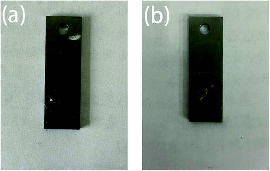 |
| | Fig. 11 Corrosion comparison chart of two coatings after being soaked in 3.5% NaCl for 240 h: (a) pure water-based acrylic coating; (b) Mn-MOFs@Zn@acrylic coating. | |
4 Conclusions
The Mn-MOFs was successfully prepared and zinc phosphate was loaded into the material which had excellent pH response performance. When the pH of the system changes, the Mn-MOFs@Zn can quickly collapse and release zinc phosphate. The acrylic coating with self-healing function was successfully prepared by adding Mn-MOFs@Zn. The experimental results prove that the corrosion inhibition performance of the Mn-MOFs@Zn@acrylic coating was significantly improved compared with the pure water-based acrylic coating. When the Mn-MOFs@Zn@acrylic coating was damaged, it can quickly release zinc phosphate, and can repair the damaged parts of the metal in time to extend the protective effect of the coating on the mild steel. Therefore, Mn-MOFs@Zn@acrylic coating may be a potential candidate material for carbon steel protection.
Conflicts of interest
There are no conflicts to declare.
Acknowledgements
This work was supported by the National Nature Science Foundation of China (No. 61661014, 21266006 and 21661010), the Nature Science Foundation of Guangxi Province (No. 2018GXNSFAA294042, 2017GXNSFGA198005, 2018GXNSFBA281135, 2018GXNSFAA281198 and 2018GXNSFBA281114), Guangxi One Thousand Young and Middle-aged College and University Backbone Teachers Cultivation Program for the support.
References
- Y. Gonzalez-Garcia, S. Gonzalez and R. M. Souto, Corros. Sci., 2007, 49, 3514–3526 CrossRef CAS.
- B. Nikravesh, B. Ramezanzadeh, A. A. Sarabi and S. M. Kasiriha, Corros. Sci., 2011, 53, 1592–1603 CrossRef CAS.
- C. G. Oliveira and M. G. S. Ferreira, Corros. Sci., 2003, 45, 123–138 CrossRef.
- A. A. Javidparvar, R. Naderi and B. Ramezanzadeh, Colloids Surf., A, 2020, 602, 125061 CrossRef CAS.
- J. R. Xavier, Mater. Sci. Eng., B, 2020, 260, 114639 CrossRef CAS.
- T. P. Chou, C. Chandrasekaran, S. J. Limmer, S. Seraji, Y. Wu, M. J. Forbess, C. Nguyen and G. Z. Cao, J. Non-Cryst. Solids, 2001, 290, 153–162 CrossRef CAS.
- G. Grundmeier, W. Schmidt and M. Stratmann, Electrochim. Acta, 2000, 45, 2515–2533 CrossRef CAS.
- Y. K. Kang, X. H. Chen, S. Y. Song, L. G. Yu and P. Y. Zhang, Appl. Surf. Sci., 2012, 258, 6384–6390 CrossRef CAS.
- Y. J. Wan, L. C. Tang, L. X. Gong, D. Yan, Y. B. Li, L. B. Wu, J. X. Jiang and G. Q. Lai, Carbon, 2014, 69, 467–480 CrossRef CAS.
- A. C. Bastos, M. G. S. Ferreira and A. M. Simoes, Prog. Org. Coat., 2005, 52, 339–350 CrossRef CAS.
- A. Sakhri, F. X. Perrin, E. Aragon, S. Lamouric and A. Benaboura, Corros. Sci., 2010, 52, 901–909 CrossRef CAS.
- Z. Sanaei, G. Bahlakeh and B. Ramezanzadeh, J. Alloys Compd., 2017, 728, 1289–1304 CrossRef CAS.
- S. Asaldoust and B. Ramezanzadeh, J. Colloid Interface Sci., 2020, 564, 230–244 CrossRef CAS.
- Y. T. Wu, S. G. Wen, K. M. Chen, J. H. Wang, G. Y. Wang and K. Sun, Prog. Org. Coat., 2019, 132, 409–416 CrossRef CAS.
- E. Alibakhshi, A. Naeimi, M. Ramezanzadeh, B. Ramezanzadeh and M. Mahdavian, J. Alloys Compd., 2018, 762, 730–744 CrossRef CAS.
- K. X. Ye, Z. X. Bi, G. Cui, B. J. Zhang and Z. L. Li, Corrosion, 2020, 76, 279–298 CrossRef CAS.
- H. C. Qian, D. K. Xu, C. W. Du, D. W. Zhang, X. G. Li, L. Y. Huang, L. P. Deng, Y. C. Tu, J. M. C. Mol and H. A. Terryn, J. Mater. Chem. A, 2017, 5, 2355–2364 RSC.
- T. Wang, J. Du, S. Ye, L. H. Tan and J. J. Fu, ACS Appl. Mater. Interfaces, 2019, 11, 4425–4438 CrossRef CAS.
- S. An, M. W. Lee, A. L. Yarin and S. S. Yoon, Chem. Eng. J., 2018, 344, 206–220 CrossRef CAS.
- D. Crespy, K. Landfester, J. Fickert and M. Rohwerder, Adv. Polym. Sci., 2016, 273, 219–245 CrossRef CAS.
- M. Uebel, L. Exbrayat, M. Rabe, T. H. Tran, D. Crespy and M. Rohwerder, J. Electrochem. Soc., 2018, 165, C1017–C1027 CrossRef CAS.
- L. P. Lv, Y. Zhao, N. Vilbrandt, M. Gallei, A. Vimalanandan, M. Rohwerder, K. Landfester and D. Crespy, J. Am. Chem. Soc., 2013, 135, 14198–14205 CrossRef CAS.
- B. L. Zhang, W. Qiu, P. P. Wang, Y. L. Liu, J. Zou, L. Wang and J. Ma, Chem. Eng. J., 2020, 385, 123507 CrossRef CAS.
- Y. L. Li, L. P. Zheng, H. Nie, Y. F. Wang, J. H. Yao, J. Li, J. J. Li, X. L. Zhou, H. F. Wang and H. Y. Wang, J. Mol. Struct., 2020, 1204, 127427 CrossRef CAS.
- K. Y. Cao, Z. X. Yu and D. Yin, Prog. Org. Coat., 2019, 135, 613–621 CrossRef CAS.
- H. W. Tian, W. H. Li, A. Liu, X. Gao, P. Han, R. Ding, C. Z. Yang and D. P. Wang, Corros. Sci., 2018, 131, 1–16 CrossRef CAS.
- X. H. Ji, W. Wang, W. H. Li, X. Zhao, A. Liu, X. Wang, X. Y. Zhang, W. J. Fan, Y. N. Wang, Z. X. Lu, S. Liu and H. Shi, J. Taiwan Inst. Chem. Eng., 2019, 104, 227–239 CrossRef CAS.
- C. L. Zhou, Z. Li, J. Li, T. C. Yuan, B. Chen, X. Z. Ma, D. Jiang, X. H. Luo, D. C. Chen and Y. L. Liu, Chem. Eng. J., 2020, 385, 123835 CrossRef CAS.
- F. Ubaid, A. B. Radwan, N. Naeem, R. A. Shakoor, Z. Ahmad, M. F. Montemor, R. Kahraman, A. M. Abdullah and A. Soliman, Surf. Coat. Technol., 2019, 372, 121–133 CrossRef CAS.
Footnote |
| † Electronic supplementary information (ESI) available. CCDC 1981807. For ESI and crystallographic data in CIF or other electronic format see DOI: 10.1039/d0ra09753e |
|
| This journal is © The Royal Society of Chemistry 2021 |
Click here to see how this site uses Cookies. View our privacy policy here.  Open Access Article
 *c
*c

![[thin space (1/6-em)]](https://www.rsc.org/images/entities/char_2009.gif) 000 Hz, the low frequency is set to 0.01 Hz, the amplitude is set to 0.005 V, and the sensitivity is set to automatically adjust the sensitivity. The electrochemical parameters of AC impedance spectroscopy are fitted by ZView impedance fitting software.
000 Hz, the low frequency is set to 0.01 Hz, the amplitude is set to 0.005 V, and the sensitivity is set to automatically adjust the sensitivity. The electrochemical parameters of AC impedance spectroscopy are fitted by ZView impedance fitting software.


