 Open Access Article
Synthesis of g-C3N4/TiO2 nanostructures for enhanced photocatalytic reduction of U(VI) in water
Yuelin Liuab,
Shanshan Wuc,
Jun Liu d,
Shuibo Xie*ce and
Yingjiu Liuc
aKey Discipline Laboratory for National Defence for Biotechnology in Uranium Mining and Hydrometallurgy, University of South China, Hengyang 421001, China
bSchool of Civil Engineering, Hunan University of Technology, Zhuzhou 412007, China
cHunan Province Key Laboratory of Pollution Control and Resources Reuse Technology, University of South China, Hengyang 421001, China. E-mail: xiesbmr@263.net
dHunan Key Laboratory of Biomedical Nanomaterials and Devices, School of Life Science and Chemistry, Hunan University of Technology, Zhuzhou 412007, China
eSchool of Civil Engineering, University of South China, Hengyang 421001, China
First published on 25th January 2021
Abstract
Photocatalytic technology is a valid solution for the remediation of wastewater containing uranium. In this study, the synthesis of Z-scheme g-C3N4/TiO2 catalysts was made by a thermal synthetic approach for photocatalytic U(VI) reduction. The characterization results revealed the successful synthesis of g-C3N4/TiO2 nanostructures. The g-C3N4 surface was uniformly coated with TiO2 nanoparticles. The depletion of U(VI) in water evaluated the photocatalytic activity of g-C3N4/TiO2 under UV light irradiation. The photocatalytic tests showed that g-C3N4/TiO2 exhibited more effective photocatalytic activity than the raw materials (1.64 and 56.97 times higher than TiO2(P25) and g-C3N4, respectively). Besides, a pseudo-first-order model was followed by the experimental kinetic data for the photocatalytic process. Moreover, g-C3N4/TiO2 still presented high photocatalytic activity after four reacting cycles. Based on these experiment results, the improved photocatalytic activity could be attributed to the Z-scheme mechanism, which decreased the recombination of photo-produced electrons and holes. The synthesis of these g-C3N4/TiO2 nanomaterials provides a facile and inexpensive method for treating wastewater containing U(VI).
1. Introduction
As nuclear energy develops, uranium increasingly has entered the water environment, which seriously threatens human health.1 Therefore, the treatment of wastewater containing uranium has become a research focus. The primary idea to solve this problem is to convert soluble U(VI) into insoluble U(IV) to separate it from the water.2 Under light illumination, photocatalysts can produce electrons and holes for redox reactions. It has been proven to be an effective approach of treating wastewater containing U(VI). Compared with traditional treatment methods, photocatalysis has the advantages of simple operation, low energy consumption and no secondary pollution.3The photocatalyst is the main point in a photocatalytic reaction process. As the most classic photocatalyst, TiO2 has attracted the attention of researchers for its high activity and stability.4 TiO2 commodity P25 is the only photocatalyst used in commercials currently. However, the poor visible light responsiveness limits its further applications.5,6 Recently, various new photocatalysts have been developed such as graphitic carbon nitride (g-C3N4), iron oxide (α-Fe3O4), ZnO and noble metals.7–12 Among them, g-C3N4 has been a new focus issue in the photocatalytic field because of its narrow bandgap, which can increase the range of light absorption. Moreover, researchers have tried to improve the photocatalytic performance by modifying the photocatalysts. At present, there are three main modification methods for catalysts, such as morphology control, element doping and a variety of materials for composites.13,14 Among these modification methods, composite materials could avoid many disadvantages and limitations of a single semiconductor in a photocatalytic process. In many mechanisms of composite, the Z-scheme photocatalytic mechanism was proposed on a composite, whereby the photo-produced electrons (with less potential energy) of a semiconductor photocatalyst and the holes (with less potential energy) of another semiconductor were recombined through an interface connection, thus leaving the photo-produced electrons with higher potential energy and holes on their respective semiconductors to form active sites.15,16 It could efficiently separate photo-produced electrons and holes, thereby inhibiting their recombination.17,18 According to an authoritative report, there are no more than 40 studies about the photocatalytic reduction of U(VI).19 Among these reports are even fewer reports on the application of Z-scheme photocatalyst to reduce U(VI).20–23 However, there have been numerous reports about the application of Z-scheme photocatalysts to remove other pollutants in water.24,25 Therefore, the research on the application of Z-scheme photocatalysts for photocatalytic reduction of U(VI) is innovative. Moreover, the research on the mechanism of U(VI) reduction by the Z-scheme photocatalyst would help increase photocatalytic efficiency.
In this paper, g-C3N4/TiO2 composites were presented for photocatalytic U(VI) reduction application. TiO2 (P25) nanoparticles were coated on g-C3N4 to form a Z-scheme photocatalyst by a thermal synthetic method. The morphology and structure characterizations were presented subsequently. U(VI) reduction in aqueous was employed for evaluating the photocatalytic activities of this g-C3N4/TiO2. Moreover, the Z-scheme photocatalytic mechanism of g-C3N4/TiO2 was investigated, which could decrease the recombination of photo-produced electrons and holes.
2. Experimental
2.1 Preparation of material
Chemical reagents applied in this research were all at analytical grade without further purification. All the reagents were domestic. The TiO2 particle used in this study was P25, which was purchased from King Chemical. Standard U(VI) solution was prepared by dissolving U3O8(99%) with HCl and H2O2 under heating conditions. The porcelain crucible containing some urea was placed in a muffle furnace, and the temperature was raised from room temperature to 600 °C for 2 h, and then cooled down naturally. The ceramic crucible was removed, and its content was grounded into powder to obtain the yellow g-C3N4 photocatalyst. A certain amount of TiO2 and g-C3N4 were placed into three beakers. The surface-mass ratio of g-C3N4/TiO2 was maintained at 1![[thin space (1/6-em)]](https://www.rsc.org/images/entities/char_2009.gif) :
:![[thin space (1/6-em)]](https://www.rsc.org/images/entities/char_2009.gif) 1, 2
1, 2![[thin space (1/6-em)]](https://www.rsc.org/images/entities/char_2009.gif) :
:![[thin space (1/6-em)]](https://www.rsc.org/images/entities/char_2009.gif) 1 and 3
1 and 3![[thin space (1/6-em)]](https://www.rsc.org/images/entities/char_2009.gif) :
:![[thin space (1/6-em)]](https://www.rsc.org/images/entities/char_2009.gif) 1, marked as g-C3N4/TiO2-1, g-C3N4/TiO2-2 and g-C3N4/TiO2-3, respectively. The raw materials were then added into deionized water, stirred evenly, and ultrasonic mixed for 15 min until the powder had completely dispersed. The suspension was transferred into a ceramic crucible and heated to powder form at 80 °C for 5 h. Then, the ceramic crucible was calcined at 400 °C for 2 h in a muffle furnace. After being cooled to indoor temperature, the ceramic crucible was removed and its content grounded into powder to obtain the composite photocatalyst.
1, marked as g-C3N4/TiO2-1, g-C3N4/TiO2-2 and g-C3N4/TiO2-3, respectively. The raw materials were then added into deionized water, stirred evenly, and ultrasonic mixed for 15 min until the powder had completely dispersed. The suspension was transferred into a ceramic crucible and heated to powder form at 80 °C for 5 h. Then, the ceramic crucible was calcined at 400 °C for 2 h in a muffle furnace. After being cooled to indoor temperature, the ceramic crucible was removed and its content grounded into powder to obtain the composite photocatalyst.
2.2 Characterization
The characterization was performed on the g-C3N4/TiO2-1 sample. X-ray diffraction (XRD) characterized the crystal structure of the photocatalyst by applying a D/MAX-RB diffractometer (Bruker, D8 advance, Germany) and adopting Cu Ka radiation (ranging from 5° to 95°, Step length: 0.01°, each step 0.1 s). Scan electron microscopy (SEM), which was tested by a SUPRATM55 high-resolution field emission scanning electron microscope (operating voltage of 2 kV, standard aperture diaphragm of 30 μm, SE2 secondary electron detector imaging) (Zeiss, Germany), analyzed the surface morphology of the photocatalyst. X-ray photoelectron spectroscopy (XPS, Thermo Scientific, Escalab 250Xi, UK) was used to perform the surface elemental analysis of the photocatalyst by applying an ESCALAB II XPS system. UV-vis Diffuse Reflectance Spectra (DRS) was examined to obtain the optical absorption property of the photocatalyst (Shimadzu, UV-3600, Japan, equipped with an integrating sphere). The specific surface area was calculated by the Brunauer–Emmett–Teller (BET) method (Micromeritics ASAP 2460 instrument at 77 K with N2 as absorbate). A Xe lamp, as an excitation source, was used to record the PL spectra on a fluorescence spectrophotometer (FS5, Edinburgh Instruments Ltd., UK).2.3 Photocatalytic activities of photocatalysts
The photocatalytic reduction of U(VI) solution evaluated the photocatalytic activities of the photocatalysts prepared. In the photocatalytic process, 0.02 g of as-prepared photocatalysts was added into 50 mL of U(VI) solution (initial concentration of 10 mg L−1). Moreover, 2 mL of methanol was added into the suspension, which was used as the hole scavenger in the reaction. The mixture was ultrasonic oscillated for 30 min to disperse the photocatalysts. The pH of the suspension was adjusted to about 5.0 by hydrochloric acid and sodium hydroxide. For the elimination of the dissolved oxygen and realization of the adsorption–desorption equilibrium under anaerobic conditions, the suspension was bubbled with nitrogen (99.99%) for 30 min in the dark. Then, the mixture was illuminated by an ultraviolet light of 500 W. The photocatalytic process was carried out in the photocatalytic apparatus (GG-GHX-V, Shanghai Guigo Industrial Co. Ltd). Arsenazo III Spectrophotometric Method, used after centrifugation at regular intervals, determined the U(VI) concentration of the mixture. The following expression was used to calculate the removal ratios (RU(VI)) of U(VI):| RU(VI) = 1 − Ct/C0 = (A0 − At)/A0 × 100% |
3. Results and discussion
3.1 Structural characterization of g-C3N4/TiO2 nanostructures
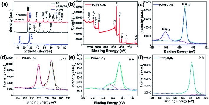
The characterization of the as-obtained g-C3N4, TiO2 (P25) and g-C3N4/TiO2 nanostructures were made by XRD and XPS techniques. The XRD patterns for these nanostructures are presented in Fig. 1a. In the XRD pattern of pure g-C3N4 (blue line), the significant diffraction peaks appeared at positions of 13.1° and 27.3°, and are indexed to (100) and (002) planes of g-C3N4. These are attributed to the planar, which repeats cell structure and sandwich stack reflection of g-C3N4.26,27 The average interlayer distances were 0.675 nm and 0.326 nm, respectively, calculated by the Scherrer equation. After compositing with TiO2 (P25), the significant peaks of g-C3N4 still had decreased peak intensity. The apparent diffraction peaks of anatase TiO2 and rutile TiO2 are shown in the g-C3N4/TiO2 nanostructures (red line), where most of these peaks displayed (101), (004), (200), (105), (211), (204), (116), (220) and (215) planes of anatase TiO2,28 while other peaks were attributed to (110), (101), (111) and (220) planes of rutile TiO2. These peaks are according to the XRD results of pure P25 (black line).Moreover, Fig. 1b–f show the XPS spectra of g-C3N4/TiO2 nanostructures. In Fig. 1b, the full XPS spectrum presented all the peaks (C 1s, N 1s, Ti 2p, O 1s) of g-C3N4 plus TiO2 nanomaterials. Fig. 1c–f showed high-resolution XPS spectra of Ti 2p, C 1s, N 1s and O 1s. After employing the XPS-peak-differentiation-imitating analysis method, Ti 2p1/2 and Ti 2p3/2 peaks appeared in Fig. 1c. C 1s and N 1s further confirmed the successful synthesis of g-C3N4 (Fig. 1d and e). The two C 1s that peaked at 284.8 and 288.0 eV, respectively, were caused by an aromatic carbon atom and C–N–C coordination (Fig. 1d). The O 1s identified that the TiO2 existed in these nanostructures (Fig. 1f). Thus, the generation of g-C3N4/TiO2 nanostructures can be confirmed by these structural characterizations.
3.2 Morphology of g-C3N4/TiO2 nanostructures
The SEM images of as-synthesized pure g-C3N4, TiO2 (P25) and g-C3N4/TiO2 nanostructures are presented in Fig. 2. The g-C3N4 polymer with a blocky structure was gathered by many irregularly shaped wrinkled sheets, as displayed in Fig. 2a. These blocky structures with holes of g-C3N4 polymers could be reported as per the magnified SEM image of g-C3N4 (Fig. 2b). These holes may give the g-C3N4 many active reaction sites for various applications. The SEM images of the pure TiO2 (P25) are shown in Fig. 2c and d. As shown in these images, the particle size of TiO2 (P25) was too small (less than 100 nm) compared with g-C3N4. It was more favorable for TiO2 to disperse on the surface of g-C3N4. After compositing TiO2 with g-C3N4, TiO2 nanoparticles uniformly adhered to g-C3N4 (Fig. 2e and f). This combination could promote the charge transfer between g-C3N4 and TiO2 by the Z-scheme route. However, as presented in Fig. 2e, there still certain parts of g-C3N4 that were uncovered due to the imprecise control of the hydrothermal method. This result further displays the successful synthesis of the g-C3N4/TiO2 nanostructures.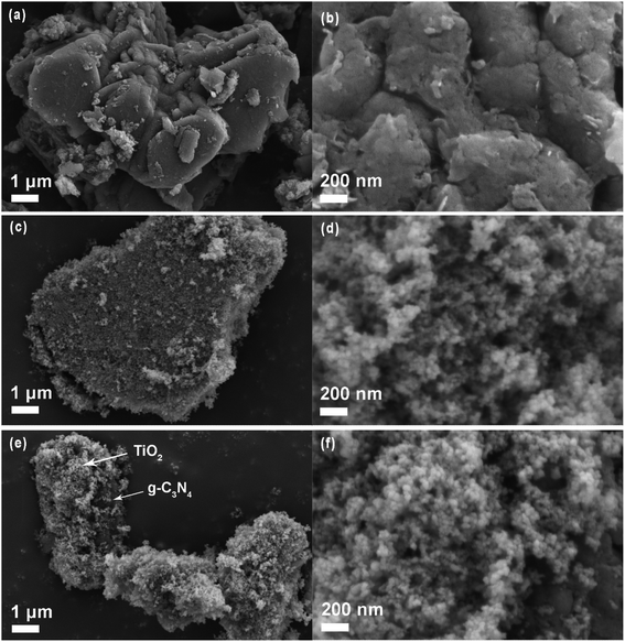 | ||
| Fig. 2 SEM images of pure g-C3N4 (a and b), TiO2 (P25, c and d) and g-C3N4/TiO2 nanostructures (e and f). | ||
3.3 Surface area of g-C3N4/TiO2 nanostructures
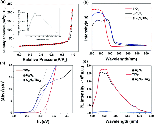
Adsorption and desorption experiments by N2 were carried out at 77 K, and N2 isotherms have been applied to calculate the specific surface area by the multi-point BET method. As shown in Fig. 3a, the shape of the isotherm with two capillary condensation steps is like a type IV isotherm according to the IUPAC classification, indicating the presence of mesopores. The shape of the hysteresis loop was of the type H3, and the hysteresis loop shifts at high relative pressures (P/P0) between 0.8 and 1.0, which suggests a mesoporous structure. Mesoporosity is typical of wrinkled, sheet-like particles, and this result is consistent with SEM images. This mesopore size distribution was confirmed by the pore size distributions shown in the inset in Fig. 3a. The average pore diameter of g-C3N4/TiO2 nanostructures is estimated as 37 Å, which suggests the existence of mesopores. The BET specific area of the g-C3N4/TiO2 nanostructures was 36.2 m2 g−1, which is between g-C3N4 (29.4 m2 g−1) and TiO2 (51.6 m2 g−1).3.4 Optical properties of g-C3N4/TiO2 nanostructures
Firstly, UV-vis diffuse reflectance spectroscopy (DRS) was used to investigate the optical properties of pure g-C3N4, TiO2 (P25) and g-C3N4/TiO2 nanostructures. As shown in Fig. 3b, the significant absorption peak of g-C3N4 was at ∼398 nm, the absorption end of g-C3N4 was ∼450 nm (black line). The pure TiO2 (P25) showed a high UV-light absorption, and the absorption edge was ∼400 nm (red line). After compositing TiO2 with g-C3N4, the absorption edge was located on the range between 400 and 450 nm, and the absorption intensity in the UV region was lower than pure TiO2 but higher than g-C3N4 (blue line), which reveals a successful synthesis of the g-C3N4/TiO2 nanostructures. According to the plot of (Ahv)2 versus (hv), as shown in Fig. 3c, the bandgap energies (Eg) of pure g-C3N4, TiO2 (P25) and g-C3N4/TiO2 have been estimated to be 2.7 eV, 3.2 eV and 2.75 eV, respectively. The calculation results show that the bandgap width of g-C3N4/TiO2 nanostructures was very close to that of g-C3N4, which is narrower than that of TiO2 (P25).PL spectra were the principal approach to test the efficiency of charge separation during the photocatalytic process.16 The release of energy in the form of PL emission was made while recombining electron–hole pairs. Therefore, greater PL intensity shows a greater recombination rate of charge carriers. Hence, the PL spectra of pure g-C3N4, TiO2 (P25) and g-C3N4/TiO2 nanostructures were performed in Fig. 3d. For pure g-C3N4 and TiO2 (P25), there is a relatively strong emission peak at ∼452 nm, which is displayed in the PL spectra (black line and red line), indicating that there are many photo-produced electrons combined with holes. A large amount of energy is released, which is detected by the PL spectra. For g-C3N4/TiO2, there is no prominent emission peak in PL spectra (blue line). This phenomenon indicates the decreased recombination efficiency of photo-produced electrons and holes, which enhanced the photocatalytic performance of g-C3N4/TiO2 because of its Z-scheme structure.29
3.5 Photocatalytic reduction of U(VI)
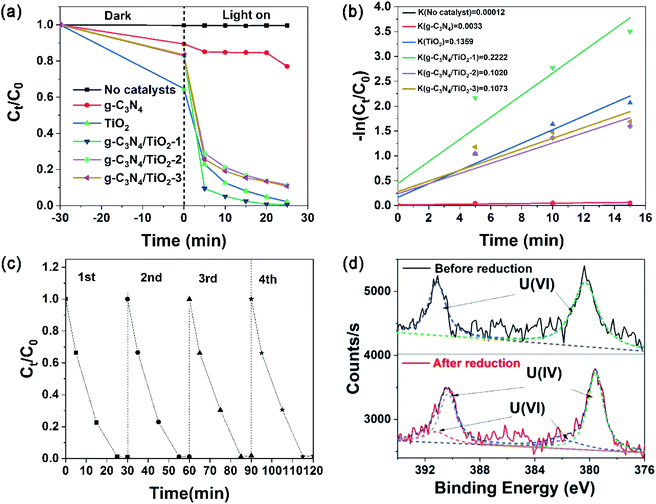
U(VI) reduction was used to evaluate the photocatalytic activity of the photocatalysts. Fig. 4a and b show the results. Without photocatalysts, there is no obvious change of U(VI) concentration, showing U(VI) stability under light and negligible self-photocatalysis process. Under the condition of adding photocatalyst, the U(VI) concentration reduces slightly after the dark reaction reaches adsorption equilibrium in the first 30 min. It is indicated that photocatalyst has a certain adsorption ability for U(VI). For pure g-C3N4, U(VI) concentration does not decline obviously after the light is turned on, which shows that the photocatalytic effect of pure g-C3N4 for U(VI) is greatly restricted. For TiO2, g-C3N4/TiO2-1, g-C3N4/TiO2-2 and g-C3N4/TiO2-3, the U(VI) concentration drop rapidly in the first 5 min after the light is turned on. The U(VI) concentration decreases gradually in the following 20 min. As the most active photocatalyst, g-C3N4/TiO2-1 removed >99% of U(VI) after illumination for 25 min. The reaction kinetics for the removal of U(VI) quantitatively was researched by pseudo-first-order kinetics model. As expressed in the formula −ln(C0/Ct) = kt, where k stands for the apparent reaction rate constant, C0 and Ct are the concentrations of aqueous U(VI) at reaction time t0 and t, respectively. As displayed in Fig. 4b, the apparent rate constants k for g-C3N4, TiO2, g-C3N4/TiO2-1, g-C3N4/TiO2-2 and g-C3N4/TiO2-3 were calculated to be 0.0033, 0.1359, 0.2222, 0.1020 and 0.1073 min−1, respectively. As the maximum in the series photocatalysts, the k values of g-C3N4/TiO2-1 was 1.64 times of TiO2 (the maximum of raw material), indicating that the photocatalytic performance has been significantly improved through the material composite.The long-time stability of a photocatalyst during the photocatalytic reaction is significant for practical use. Fig. 4c shows the recycling usability of four times for g-C3N4/TiO2-1 in the photocatalytic process. After each cycle, centrifugation collected and separated the photocatalysts from the suspension aqueous. Photocatalysts were ultrasonic oscillated to peel off surface sediments and then washed by deionized water. Subsequently, the drying of photocatalysts was carried out at 60 °C before the next recycle. As shown in Fig. 4c, the curves for each cycle were very similar. The final removal rate of every cycle was more than 99%, which indicates the stable photocatalytic activity of g-C3N4/TiO2 after several recycles.
XPS spectra of U element on g-C3N4/TiO2 nanostructures were performed for verification of the reduction process. Fig. 4d shows higher resolution XPS spectra of U 4f (after and pre-reduction). After the reduction of U(VI) into U(IV), the peak positions of U 4f5/2 and 4f7/2 were changed. In the bottom red curve, the peak-differentiating technique was used to obtain four peaks located at 379.6, 381.9, 390.4, and 391.3 eV. The two peaks at 381.9 and 391.3 eV originated from U(VI), these positions were matched well with that of U(VI) sample without reduction (up to black line), and peaks at 379.6 and 390.4 eV belong to U(IV). The above results showed that most of the U(VI) on the surface of g-C3N4/TiO2 nanostructures were reduced into U(IV).30
3.6 Reduction mechanisms of U(VI)
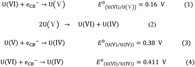
After the above results and discussion, Fig. 5 proposed the possible mechanism of g-C3N4/TiO2 photocatalytic reduction of U(VI). g-C3N4 and TiO2 formed their photo-produced electrons and holes, respectively, in their internal parts under light irradiation. According to the relative position of VB and CB in g-C3N4 and TiO2, the photo-produced electrons produced by TiO2 migrate to the interface of g-C3N4/TiO2 and integrate holes in the part of g-C3N4. The photo-produced electrons produced by g-C3N4 are used as a reduction site to reduce the U(VI) into U(IV). The holes in the VB of TiO2 oxidize methanol into CO2 and H2O as oxidation sites. In this way, the photo-produced electrons and holes involved in the redox reaction are reacted on their respective semiconductors. The recombination of photo-produced electrons and holes is effectively avoided, increasing photocatalytic efficiency.31 At present, there are two mainstream opinions about the reduction process of U(VI).19 In the first opinion, the reduction process of U(VI) consists of two steps,32 which is shown as eqn (1)–(3) in Scheme 1. U(VI) is reduced to U(V) by photo-produced electrons in the first step (eqn (1)). U(V) can spontaneously react to U(VI) and U(IV) (eqn (2)), which follows the principle of electronic equilibrium. Moreover, U(V) can be further reduced to U(IV) by photo-produced electrons (eqn (3)). Another opinion indicated that U(VI) could be reduced to U(IV) directly just as eqn (4) in Scheme 1.33 As displayed in Fig. 5, the reduction potential of CB on g-C3N4 (E0 = −1.3 eV) was more passive than the decreased potential for a series of reactions. Theoretically, the reduction reaction can proceed smoothly.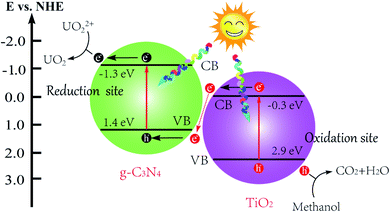 | ||
| Fig. 5 The diagram of the proposed mechanism of g-C3N4/TiO2 nanostructures under simulated sunlight irradiation. | ||
4. Conclusions
A thermal synthetic approach was proposed for the synthesis of Z-scheme catalyst g-C3N4/TiO2. According to the results of characterization, a successful synthesis of g-C3N4/TiO2 nanostructures was revealed. By comparing with raw materials, g-C3N4/TiO2 displayed much greater photocatalytic activities for the reduction of radioactive U(VI) under the condition of UV light illumination (1.64 times higher of TiO2 and 56.97 times of g-C3N4). More than 99% of U(VI) was removed by g-C3N4/TiO2 after illumination for 25 min. XPS analyses showed that most of the U(VI) on the surface of g-C3N4/TiO2 were reduced into U(IV). After the reaction kinetics analysis, the photocatalytic reaction follows pseudo-first-order kinetics. Moreover, the g-C3N4/TiO2 displayed good stability after four reused tests. Its Z-scheme structure, which decreased recombination efficiency of photo-produced electrons and holes, could cause the enhancement of the photocatalytic activities of g-C3N4/TiO2. In summary, the g-C3N4/TiO2 practically represent a suitable in U(VI) photocatalytic reduction.Author contributions
Yuelin Liu contributed to the conception and design of the study. Shanshan Wu contributed to the acquisition of data. Yuelin Liu and Jun Liu contributed to the analysis and interpretation of data. Yuelin Liu contributed to drafting the manuscript. Shuibo Xie and Jun Liu contributed to revising it critically for important intellectual content. Shuibo Xie and Yingjiu Liu contributed to the reagents/materials/analysis tools.Conflicts of interest
The authors declare no conflict of interest.Acknowledgements
The authors are grateful to the Laboratory of Pollution Control and Resource Technology and the Department of Municipal Engineering at the University of South China for providing the necessary facilities for the research. This research was funded by the National Natural Science Foundation of China (NO. 11475080). Natural Science Foundation of Hunan Province (No. 2019JJ50127).References
- M. J. Manos, et al., Layered Metal Sulfides Capture Uranium from Seawater, J. Am. Chem. Soc., 2012, 134, 16441–16446 CrossRef CAS.
- Y. Liu, et al., Removal of uranium(VI) from aqueous solutions by CMK-3 and its polymer composite, Appl. Surf. Sci., 2013, 285, 258–266 CrossRef CAS.
- H. Yu, et al., The synergistic effect of graphitic N and pyrrolic N for the enhanced photocatalytic performance of nitrogen-doped graphene/TiO2 nanocomposites, Appl. Catal., B, 2016, 810–817 Search PubMed.
- J. Yu, et al., Enhanced Photocatalytic CO2 Reduction Activity of Anatase TiO2 by Co exposed {001} and {101} Facets, J. Am. Chem. Soc., 2014, 136, 8839–8842 CrossRef CAS.
- N. Bao, et al., Self-Templated Synthesis of Nanoporous CdS Nanostructures for Highly Efficient Photocatalytic Hydrogen Production under Visible Light, Cheminform, 2008, 39, 110–117 Search PubMed.
- L. A. Silva, et al., Photocatalytic Hydrogen Production with Visible Light over Pt-Interlinked Hybrid Composites of Cubic-Phase and Hexagonal-Phase CdS, J. Phys. Chem. C, 2008, 112, 12069–12073 CrossRef CAS.
- J. Wen, et al., A review on g-C3N4-based photocatalysts, Appl. Surf. Sci., 2017, 391, 72–123 CrossRef CAS.
- Y. Guo, et al., Adsorption and photocatalytic reduction activity of uranium(VI) on zinc oxide/rectorite composite enhanced with methanol as sacrificial organics, J. Radioanal. Nucl. Chem., 2016, 883–890 CrossRef CAS.
- A. Lassoued, et al., Photocatalytic degradation of methylene blue dye by iron oxide (alpha-Fe2O3) nanoparticles under visible irradiation, J. Mater. Sci.: Mater. Electron., 2018, 29, 8142–8152 CrossRef CAS.
- Y. Guo, et al., Enhanced photocatalytic reduction activity of Uranium(VI) from aqueous solution using Fe2O3-Graphene oxide nanocomposite, Dalton Trans., 2017, 46, 14762–14770 RSC.
- J. Liu, et al., Recent progress on photocatalytic heterostructures with full solar spectral responses, Chem. Eng. J., 2020, 393, 124719 CrossRef CAS.
- J. Liu, et al., Catalytic Application and Mechanism Studies of Argentic Chloride Coupled Ag/Au Hollow Heterostructures: Considering the Interface Between Ag/Au Bimetals, Nanoscale Res. Lett., 2019, 14, 35 CrossRef.
- X. Wu, et al., Constructing effective photocatalytic purification system with P-introduced g-C3N4 for elimination of UO22+, Appl. Surf. Sci., 2017, 430, 371–379 CrossRef.
- W. Zhen, et al., Novel visible-light-driven Z-scheme Bi12GeO20/g-C3N4 photocatalyst: Oxygen-induced pathway of organic pollutants degradation and proton assisted electron transfer mechanism of Cr(VI) reduction, Appl. Catal., B, 2017, 207, 17–26 CrossRef.
- J. Tian, et al., Novel Z-Scheme g-C3N4/C@Bi2MoO6 composite with enhanced visible-light photocatalytic activity for beta-naphthol degradation, Separation and Purification Technology, 2017, 183, 54–65 CrossRef.
- J. Liu, et al., Synthesis and photocatalytic application of trinary structural g-C3N4/Ag/Ag3PO4 composite nanomaterials, J. Environ. Chem. Eng., 2017, 5, 5777–5785 CrossRef CAS.
- N. Tian, et al., Mediator-free direct Z-scheme photocatalytic system: BiVO4/g-C3N4 organic-inorganic hybrid photocatalyst with highly efficient visible-light-induced photocatalytic activity, Dalton Trans., 2015, 44, 4297–4307 RSC.
- M. Mao, et al., Designing all-solid-state Z-Scheme 2D g-C3N4/Bi2WO6 for improved photocatalysis and photocatalytic mechanism insight, Green Energy & Environment, 2018, 3, 229–238 Search PubMed.
- L. Ping, et al., An overview and recent progress in the heterogeneous photocatalytic reduction of U(vi), J. Photochem. Photobiol., C, 2019, 100320 Search PubMed.
- R. N. Tio, et al., Photocatalytic Reduction of Uranyl Ions over Anatase and Rutile Nanostructured TiO2, Chem. Lett., 2013, 42, 689–690 CrossRef.
- V. N. Salomone, et al., New insights in the heterogeneous photocatalytic removal of U(VI) in aqueous solution in the presence of 2-propanol, Chem. Eng. J., 2015, 261, 27–35 CrossRef CAS.
- J. Feng, et al., Photocatalytic reduction of Uranium(VI) under visible light with Sn-doped In2S3 microspheres, Chemosphere, 2018, 212, 114–123 CrossRef CAS.
- L. Hu, et al., Integration of adsorption and reduction for uranium uptake based on SrTiO3/TiO2 electrospun nanofibers, Appl. Surf. Sci., 2018, 428, 819–824 CrossRef CAS.
- C. Chen, et al., Z-scheme structure SnS2–Au–CdS with excellent photocatalytic performance for simultaneous removal of Cr(VI) and methyl orange, Res. Chem. Intermed., 2019, 45, 3513–3524 CrossRef CAS.
- C. Zhu, et al., Fabrication of Z-scheme Ag3PO4/MoS2 composites with enhanced photocatalytic activity and stability for organic pollutant degradation, Appl. Surf. Sci., 2016, 377, 99–108 CrossRef CAS.
- X. Zhang, et al., Enhanced Photoresponsive Ultrathin Graphitic-Phase C3N4 Nanosheets for Bioimaging, J. Am. Chem. Soc., 2012, 135, 18–21 CrossRef.
- S. Yang, et al., Exfoliated Graphitic Carbon Nitride Nanosheets as Efficient Catalysts for Hydrogen Evolution Under Visible Light, Adv. Mater., 2013, 25, 2452–2456 CrossRef CAS.
- J. Liu, et al., 3D flowerlike α-Fe2O3@ TiO2 core–shell nanostructures: general synthesis and enhanced photocatalytic performance, ACS Sustainable Chem. Eng., 2015, 3, 2975–2984 CrossRef CAS.
- X. She, et al., High Efficiency Photocatalytic Water Splitting Using 2D alpha-Fe2O3/g-C3N4 Z-Scheme Catalysts, Adv. Energy Mater., 2017, 7, 1700025 CrossRef.
- C. Lu, et al., Photocatalytic reduction elimination of UO22+ pollutant under visible light with metal-free sulfur doped g-C3N4 photocatalyst, Appl. Catal., B, 2017, 200, 378–385 CrossRef CAS.
- P. Zhou, et al., All-Solid-State Z-Scheme Photocatalytic Systems, Advanced Materials, 2014, 26, 4920–4935 CrossRef CAS.
- M. I. Litter, Last advances on TiO2 photocatalytic removal of chromium, uranium and arsenic, Current Opinion in Green and Sustainable Chemistry, 2017, 6, 150–158 CrossRef.
- C. Lu, et al., Boron doped g-C3N4 with enhanced photocatalytic UO22+ reduction performance, Appl. Surf. Sci., 2016, 360, 1016–1022 CrossRef CAS.
| This journal is © The Royal Society of Chemistry 2021 |

