 Open Access Article
The impact of the composition and solidification rate on the microstructure and the crystallographic orientations of Al2O3–YAG–ZrO2 eutectic solidified by the micro-pulling down technique
O. Benamara and
K. Lebbou *
*
Institut Lumière Matière, UMR5306, Université Lyon1-CNRS, Université de Lyon, Lyon 69622, Villeurbanne Cedex, France. E-mail: kheirreddine.lebbou@univ-lyon1.fr
First published on 13th April 2021
Abstract
Directional solidification experiments have been carried out in eutectic and off eutectic composition in Al2O3–YAG–ZrO2 system using the micro-pulling down (μ-PD) technique. The formation of different microstructures of stable phases, over a range of velocities studied, is discussed. During the solidification process, coupled growth microsctrucure can occur at off eutectic composition. Colonies and dendrites were analysed as a function of the composition and velocity. Increasing the solidification rate resulted in a smaller grain size and instability of the crystallization interface with respect to ZrO2 segregation at the solidification front. Increasing ZrO2 in the eutectic composition showed enhanced tendency for colony and dendrite formation. When the velocity was extended to the rapid solidification regime (>1.75 mm min−1), the geometrical pattern microstructure was found to grow and a change in the growth orientation of Al2O3 corresponding to c-axis (0 0 01) was observed. Whatever the pulling rate, during the eutectic solidification the Al2O3 and ZrO2:Y phases' growth competition was observed, and 〈100〉 YAG orientation was grown along the pulling direction.
1. Introduction
Despite the very different needs for particular materials, eutectic materials have shown remarkable consistency in large technological applications such as nanotechnology and electronics.1–7 Today, there is a clear need to produce performed materials more economically and with higher reproducibility and quantity than possible currently. Among the eutectic ceramic material family, the Al2O3–YAG–ZrO2 (ref. 8–10) ternary system is of great importance. Eutectic materials have a number of properties, which make them interesting as potential engineering materials.11–13 In addition to their utilization in gas turbine engines, they can be used in ships and eventually in aircraft turbines.14,15 The use of these materials in aeronautics will depend not only on superior engineering design, but also more importantly on the availability of the eutectic ceramic with a significant advantage in high-temperature morphology and microstructure over the presently available metals and alloys. With the melting temperature around 1750 °C, the system is stable and presents performed mechanical properties.16–19 Most of their physical and mechanical properties are heavily dependent on the microstructure and morphology.Various experimental works have been carried out on the solidification of eutectic oxide materials by different processes and varying results have been obtained. Viechnicki and Schmid20,21 studied eutectics using Bridgman furnace with molybdenum crucibles and a thermal gradient of approximately 200 °C cm−1. Non-uniform “Chinese script” microstructures were obtained. Waku et al.22 successfully grew eutectics with uniform microstructure using Bridgman furnace and molybdenum crucible. Borodin et al.23 and L. Carroz et al.24,25 investigated eutectics by the Edge-defined Film Growth (EFG) method. They suspected that the non-uniformities of microstructures were caused mainly by the instability of the plane crystallization front because of constitutional supercooling. Borodin et al.26 studied eutectics by the Verneuil growth method mainly used for sapphire crystal growth. However, homogeneous microstructures were never obtained. The floating zone crucible free method using laser or lamp as heating source27–32 has been used to solidify unidirectional eutectic materials. However, in the floating zone, microstructures are often influenced by grain size materials containing many grain boundaries, which are not thermodynamically stable, and at high temperatures the grain boundary area tends to be reduced by grain growth. This technique is mainly used to obtain samples for specific characterization. Solidification of eutectic materials can be done by lowering the temperature below the melting point, which is a versatile method for solidification.33 The micro pulling down (μ-PD) technique has been used to grow eutectic fibers, rods and plates to investigate the microstructure at very high growth rate (0.1–10 mm min−1).34–40 Melt convection is suppressed by the use of a narrow nozzle, due to the capillary effect. It is easy to control the eutectic shape and composition. By the μ-PD technique, the basic solidification parameters such as the growth kinetics and compositional stability can be made clear before undertaking the Bridgman and EFG growth techniques. Most cited papers describe the particular characteristics of oxide eutectics. It has been found to be difficult to control the microstructure of the Al2O3–YAG–ZrO2 eutectic system.
Numerous compositions around the 65 mol% Al2O3–16 mol% Y2O3–19 mol% ZrO2 eutectic point have been studied in order to identify the coupled growth zone.39–42 It has been shown that depending on the eutectic composition, the solidification process and the growth parameters, the resulting microstructure consists of two phases (YAG, Zr(Y)O2) distributed in sapphire (Al2O3) matrix. The experimental works carried out17,43–50 for eutectic compositions highlight the influence of solidification parameters: growth rate, chemical composition and thermal gradient. Depending on the pulling rate conditions, the microstructure will also undergo transitions linked to the destabilization of the interface.49,51,52
Despite the different studies, experimental data for the directional solidification of oxide eutectics (processing difficulties, microstructure instabilities) are still limited and often uncertain. A systematic study of the microstructure is strongly needed before eutectic ceramic oxides can be fully developed for application. Recently, more fundamental questions are being answered with key investigation in the directional solidification method where the processing parameters such as solidification rate and composition of the eutectic are individually controlled. There is a great need for continued effort in this direction. In this paper, as a function of the pulling rate, experimental results on Al2O3–YAG–ZrO2 ternary eutectic and off eutectic solidified by the micro pulling down technique are analyzed and discussed to ascertain the solidification parameters controlling the resultant microstructure and morphology.
2. Experimental procedure
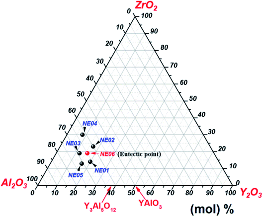
High-purity (>99.99%) Al2O3, Y2O3 and ZrO2 powders were mixed in an agate mortar according to the ternary eutectic composition 65 mol% Al2O3/16 mol% Y2O3/19 mol% ZrO2.23,31,41 The mixture was sintered at 1400 °C for 10 hours in air atmosphere. Eutectic ceramic materials were directionally solidified from the melt using the micro-pulling down technique in the same conditions presented in our previous work.39,40 In addition to the eutectic composition, we studied five different compositions around the eutectic mixture (Fig. 1). The detailed compositions are shown in Table 1.| Reference | Al2O3 (mol%) | Y2O3 (mol%) | ZrO2 (mol%) |
|---|---|---|---|
| NE01 | 66 | 20 | 14 |
| NE02 | 60 | 17 | 23 |
| NE03 | 69 | 12 | 19 |
| NE04 | 62 | 8 | 30 |
| NE05 | 71 | 16 | 13 |
| NE06 (eutectic) | 65 | 16 | 19 |
The room-temperature X-ray diffraction patterns were obtained using a Bruker D8 advanced diffractometer with Cu-Kα1 and Cu-Kα2 X-rays (λ = 0.15406 and 0.15444 nm). Scanning was done over a 2θ range from 10° to 100° in steps of 0.02° with a counting time of 16 s per step and continuous rotation (20 rpm) around the growth direction. SEM observations of the rods were performed with a Phenom desktop scanning electron microscope (FEI) at 5 kV. The composition of the solidified samples was evaluated by the inductively coupled plasma (ICP) emission and energy-dispersive X-ray spectroscopy (EDX) techniques. The TEM experiment and electronic diffraction pattern investigation were carried out using a CM20-FEG transmission electron microscope.
3. Results
3.1. Eutectic solidification and microstructure
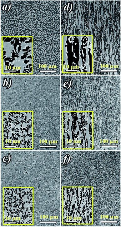
Fig. 2a shows ceramic the eutectic 5 mm diameter rods (65 mol% Al2O3/16 mol% Y2O3/19 mol% ZrO2) (NE06) and Fig. 2b shows the (NE01 → NE05) rods solidified in the vicinity of the eutectic composition. A ceramic eutectic seed 3 mm in diameter was used to initiate the growth process. In the case of the eutectic composition (NE06), whatever the pulling rate, the solidified eutectic rods exhibit a white colour with smooth surface without any visible macroscopic defects such as cracks and bubbles.Fig. 3a–c show the SEM images of the transverse sections solidified at 0.1, 0.5 and 1 mm min−1 cut from the middle region of the eutectic composition rods. Most part of the zirconia precipitates (white) are completely imbedded in the alumina (black)/YAG (light) interfaces and some of them are localized on the sapphire host. In the longitudinal section (Fig. 3d–f) the alumina host and YAG phase exhibit a broken-lamellar morphology aligned along the growth direction. For the three solidification rates, a homogeneous morphology exempt of voids and a lamellar microstructure are observed. The morphology architecture is Chinese script, which is in good agreement with ref. 40, 41 and 43 The use of high pulling rate (1 mm min−1) has led to an extensive area of apparent heterogeneities in which a Chinese script microstructure with colonies and inhomogeneous phase distribution are observed (Fig. 3c and f). The microstructure is fine for the solidification rate of 1 mm min−1. As a function of the pulling rate (v), the lamellar spacing (λ) in the ceramic rods corresponds to λ2v = constant. It being approximately 6.5 ± 1.3 μm when the solidification rate (v) is 0.1 mm min−1, 3.6 ± 0.5 μm at v = 0.5 mm min−1 and 2.9 ± 0.5 μm at v = 1 mm min−1 is in good agreement with ref. 25, 39 and 40.
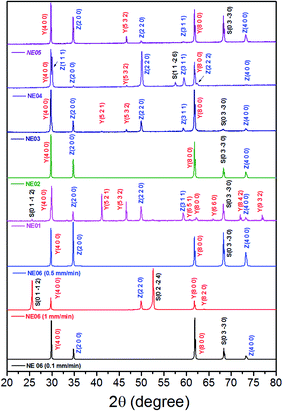
The eutectic rods being solidified at low pulling rates (0.1–0.5 mm min−1) by the coupled growth of two phases (YAG, sapphire) and dispersion of irregular ZrO2 in a continuous Al2O3 matrix leading to a homogeneous microstructure is in good agreement with these investigations: ref. 29, 39, 40, 53 and 54. Except NE02 compound, because of the continued composition evolution of (NE01, NE03, NE04 and NE05) samples in the Al2O3–Y2O3–ZrO2 ternary equilibrium diagram,41 during the solidification process it was quite difficult to control these systems. The surface samples were rough and slightly yellow coloured. As eutectic composition, mainly Al2O3, YAG and ZrO2 phases were observed (Fig. 4). To quantify the concentration of yttrium in the YZT phase and verify the chemical composition of Al2O3 and YAG phases, EDX measurements were performed on the samples. Except for the YZT grains, which exhibited an important concentration of yttrium atoms due to the substitution of Zr by Y in the ZrO2 phase, the composition of YAG and Al2O3 phases were very close to the stoichiometric theoretical composition. The concentration of Y2O3 varied approximately from 8 (NE04) to 20 mol% (NE01), in good agreement with the selected compositions in Table 1 from the Al2O3–Y2O3–ZrO2 equilibrium diagram. This result was confirmed by ICP analysis and revealed that the compositions of the solidified materials were very close to the prepared composition. On account of the stability of the melt and the no volatility of Y2O3, Al2O3 and ZrO2 compounds during the solidification process, this result was expected.
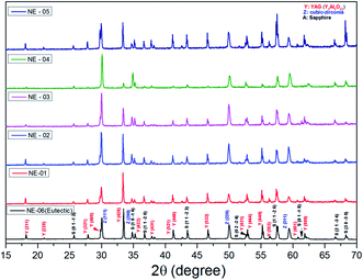 | ||
| Fig. 4 Room-temperature powder XRD patterns of crushed Al2O3/YAG/ZrO2 eutectic and off eutectic composition. | ||
The lattice parameters of each of the phases obtained from X-ray powder diffraction are shown in Table 2. Grinding the samples makes it possible to overcome the phenomena of texturing and distortion due to the internal stresses of the material at room temperature. These internal stresses originate from the difference in the thermal expansion coefficients of the Al2O3, YAG and ZrO2 phases.55–57 In the case of the eutectic point (NE06), the results are very similar between micro-pulling down, EFG, floating zone and Bridgman,24,39,58,59 which shows that the elaboration method does not have a significant effect on the lattice parameters of the isolated phases. The lattice parameters of the alumina phase are close to the theoretical values and the YAG phase has a slightly lower lattice parameter. The ZrO2 is a cubic structure stabilized by Y2O3. The lattice parameter (a) from the X-ray diffraction is averaged. The zirconia lattice parameter depends on the substitution of yttrium content according to Vegard law.60 The lattice parameter (a) is between 0.51506 nm and 0.51621 Å. It is calculated from the diffraction patterns and has a standard deviation error of ≈0.0004 nm, which corresponds to an error in the Y2O3 content. The Y2O3 content is therefore about 17.32 ± 0.37 mol%. Even with the many published papers, it is difficult to identify the source of error. It must be noted that the lattice parameter (a) measured in this study is in very good agreement with the data from ref. 61 and 62. The mechanism of solid solution of Y2O3 in cubic ZrO2 was established by F. Hund63 as substitutional replacement of Y3+ ions on Zr4+ cationic sites with a charge-compensation number of vacant anionic sites following the chemical reaction:
Al2O3 R![[3 with combining macron]](https://www.rsc.org/images/entities/char_0033_0304.gif) c c |
Y3Al5O12 (YAG) Ia![[3 with combining macron]](https://www.rsc.org/images/entities/char_0033_0304.gif) d d |
ZrO2 Fm![[3 with combining macron]](https://www.rsc.org/images/entities/char_0033_0304.gif) m60 m60 |
|
|---|---|---|---|
| Lattice parameters from PDF files | a = 0.47932 nm (ref. 65) | a = 1.20062(2) nm (ref. 66) | |
| c = 1.29925 nm | |||
| NE01 | a = 0.47581 nm | a = 1.20070(3) nm | a = 0.51603(4) nm |
| c = 1.29940 nm | |||
| NE02 | a = 0.47653 nm | a = 1.19998(4) nm | a = 0.51586(3) nm |
| c = 1.30108 nm | |||
| NE03 | a = 0.47686 nm | a = 1.19902(2) nm | a = 0.51552(4) nm |
| c = 1.29369 nm | |||
| NE04 | a = 0.47547 nm | a = 1.19753(2) nm | a = 0.51506(4) nm |
| c = 1.29600 nm | |||
| NE05 | a = 0.47583 nm | a = 1.20079(3) nm | a = 0.51621(4) nm |
| c = 1.29882 nm | |||
| NE06 (eutectic) | a = 0.47684 nm | a = 1.19931(2) nm | a = 0.51561(4) nm |
| c = 1.29133 nm |
The creation of these vacancies (V′′) is thought to stabilize the cubic polymorphs. S. M. Ho64 proposed that Zr ions in all of the polymorphs prefer a 7-fold coordination of oxygen, and that the lattice arranges itself to achieve this symmetry. By the creation of vacancies, the coordination number of the Zr atom is decreased for the cubic lattice, thereby reducing the normal fluorite structure of 8-fold to a 7-fold coordination.
Fig. 5 shows the transversal and longitudinal microstructure evolution as a function of the composition under a pulling rate of 0.5 mm min−1. All the (NE01 → NE05) samples present heterogeneities and exhibit variation in the microstructures and the morphology. As the eutectic composition, the black regions correspond to the α-Al2O3 phase, the light regions to YAG and the white one corresponds to the ZrO2:Y phase. Depending on the composition, the ZrO2:Y and YAG phases do not grow at the same conditions. For the (NE01 → NE05) compositions, different morphologies such dendrites, cells and colonies were observed. In contrast, the sample NE02 close to the NE06 eutectic point showed enhanced tendency for colony formation. However, higher alumina concentration (>62%) (NE01, NE03 and NE05) favored the formation of cellular and dendritic microstructures. Depending on the composition, the transition from coupled to cellular and dendritic microstructure can be connected to the concept of competitive growth. The variation of the microstructure for (NE01 → NE05) showed a clear tendency of the three phases to grow in preferred directions. In the eutectic point, the microstructure strongly depends on the growth rate and the crystallization thermal gradient,25,39,40,57–59 but the samples (NE01 → NE05) around the eutectic point (NE06) solidified at the same conditions presented a microstructure dispersion strongly affected by the chemical composition. In the sample NE04 corresponding to higher ZrO2 concentration (30 mol%), the grain size and the aspect shape of ZrO2 as well as the morphology and the domains were heterogeneous. In addition, some zirconia grains (white) were interconnected differently than in the other samples. The compositional range of the eutectic for coupled growth in the (Al2O3–YAG) binary and (Al2O3–YAG–ZrO2) ternary systems was narrow and any deviation from the eutectic composition generated a complex metastable morphology and even secondary phases,67 which were not observed in this work. The NE03 and NE05 samples corresponding to the higher alumina concentration showed sapphire domains, the average size was around 50 μm (NE03) and the elongated Al2O3 lamellas reached 250 μm (NE05). The NE03 sample presented broken YAG lamellas nested between segregated zirconia precipitates (Fig. 5h). Moreover, the NE01 sample corresponding to the higher concentration of Y2O3 (20%) showed YAG lamellas of length varying from 25 to 200 μm. Some lamellas were continued and slightly tilted from the rod axis. In all (NE01 → NE05) samples, the colony microstructures were surrounded by small eutectic microstructures. Outside the eutectic point, the microstructure changed dramatically with the composition; the morphology and the rate of transformation and the nucleation behaviour were affected by the amount of Y2O3 and ZrO2. Whatever the composition, an overheating of the melt up to 2000 °C was not accompanied by the formation of YAlO3 perovskite as it was observed in previous works using the EFG and floating zone methods.24,25,67,68 According to these results, there is a variety of microstructural features, which can be expected to be the cause for the different growth velocities and chemical compositions. For eutectic composition, Chinese script eutectic growth was observed from low to moderate growth rate and colonies for higher velocities. For off-eutectic composition, dendrites and cells were surrounded by eutectic composition.
3.2. Crystallographic analysis
Fig. 6 shows the room-temperature X-ray diffraction patterns of the eutectic (NE06) and off eutectic (NE01 → NE05) rods transversal sections as a function of the composition and pulling rate. They often grow preferentially along well-defined crystallographic orientations that are not necessarily the directions of easy growth of the compounds, but correspond to the structures of minimum interfacial energy as reported in ref. 39, 40 and 55. For low pulling rate (v = 0.1 and 0.5 mm min−1), in the case of the eutectic composition (NE06), the preferred growth direction of Al2O3 is (0![[1 with combining macron]](https://www.rsc.org/images/entities/char_0031_0304.gif) 10), that of YAG is (100) and that of ZrO2 is (100), which are in good agreement with that reported in ref. 27 and 69. For high solidification rate (1 mm min−1) the crystallographic planes have become (0
10), that of YAG is (100) and that of ZrO2 is (100), which are in good agreement with that reported in ref. 27 and 69. For high solidification rate (1 mm min−1) the crystallographic planes have become (0![[1 with combining macron]](https://www.rsc.org/images/entities/char_0031_0304.gif) 12) for Al2O3, (100) and (410) for YAG and finally (110) for the zirconia phase, consistent with that reported in ref. 39 and 40. Except for the NE02 sample, the crystallographic orientations of NE01, NE03, NE04 and NE05 samples are different than that of the eutectic point (NE06). For the NE03, NE04 and NE05 compositions, the preferred growth directions of the Al2O3/YAG/ZrO2 are determined as (0
12) for Al2O3, (100) and (410) for YAG and finally (110) for the zirconia phase, consistent with that reported in ref. 39 and 40. Except for the NE02 sample, the crystallographic orientations of NE01, NE03, NE04 and NE05 samples are different than that of the eutectic point (NE06). For the NE03, NE04 and NE05 compositions, the preferred growth directions of the Al2O3/YAG/ZrO2 are determined as (0![[1 with combining macron]](https://www.rsc.org/images/entities/char_0031_0304.gif) 10) Al2O3 and additional (1
10) Al2O3 and additional (1![[1 with combining macron]](https://www.rsc.org/images/entities/char_0031_0304.gif) 26) Al2O3 pick for NE04, (100), (521) and (532) for YAG and (100), (110) and (311) for ZrO2. The NE01 sample corresponding to higher Y2O3 concentration (20%) presents additional YAG peaks such (521) and (532) showing other YAG crystallographic orientations. It is clear that in addition to the competitive growth directions, there is a competitive growth of orientation relationships between the interfaces during the solidification imposed by the major phase.
26) Al2O3 pick for NE04, (100), (521) and (532) for YAG and (100), (110) and (311) for ZrO2. The NE01 sample corresponding to higher Y2O3 concentration (20%) presents additional YAG peaks such (521) and (532) showing other YAG crystallographic orientations. It is clear that in addition to the competitive growth directions, there is a competitive growth of orientation relationships between the interfaces during the solidification imposed by the major phase.
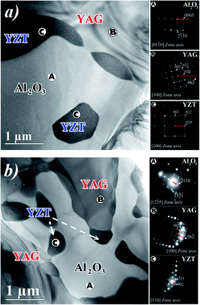
Fig. 7 shows two plan-view TEM micrographs of transverse sections of the eutectic rods solidified at 0.1 mm min−1 (Fig. 7a) and 1 mm min−1 (Fig. 7b), respectively. The A, B, C regions correspond, respectively, to the α-Al2O3, YAG and zirconia phases. We observed some zirconia grains with specific regular facets (Fig. 7b). The average sizes of the facets depended on the pulling rate and varied from 0.5 ± 0.1 μm at 1 mm min−1 to 1.5 ± 0.1 μm at 0.1 mm min−1.
In order to investigate the crystallographic relationship in the plane of the transversal section of rods, the electron diffraction pattern (SAED) was analyzed in three regions (A, B and C in Fig. 7a and b) of two eutectic samples solidified at 0.1 and 1 mm min−1. The regions A, B, C correspond, respectively, to the α-Al2O3, YAG and zirconia phases. Whatever the solidification rate, the YAG cubic phase is oriented along the [100] direction. At the pulling rate of 0.1 mm min−1, the trigonal sapphire grains are oriented along [0![[1 with combining macron]](https://www.rsc.org/images/entities/char_0031_0304.gif) 10] and become12–35 at the pulling rate of 1 mm min−1. The zirconia grains of the cubic structure are oriented along [100] and became [110] at 1 mm min−1. The SAED patterns also show that the zirconia grains located at the interface between sapphire and YAG have the same orientation as zirconia grains embedded in the sapphire host. As a function of the solidification rates, in the observation plane, the crystallographic relations between the phases are:
10] and become12–35 at the pulling rate of 1 mm min−1. The zirconia grains of the cubic structure are oriented along [100] and became [110] at 1 mm min−1. The SAED patterns also show that the zirconia grains located at the interface between sapphire and YAG have the same orientation as zirconia grains embedded in the sapphire host. As a function of the solidification rates, in the observation plane, the crystallographic relations between the phases are:
0.1 mm min−1:
[0![[1 with combining macron]](https://www.rsc.org/images/entities/char_0031_0304.gif) 10]Al2O3//[100]YAG//[100]YZT and (0003)Al2O3//(0 10]Al2O3//[100]YAG//[100]YZT and (0003)Al2O3//(0![[3 with combining macron]](https://www.rsc.org/images/entities/char_0033_0304.gif) 1)YAG//(010)YZT 1)YAG//(010)YZT |
1 mm min−1:
[1![[2 with combining macron]](https://www.rsc.org/images/entities/char_0032_0304.gif) 35]Al2O3//[100]YAG//[110]YZT and (−2110)Al2O3//(0 35]Al2O3//[100]YAG//[110]YZT and (−2110)Al2O3//(0![[3 with combining macron]](https://www.rsc.org/images/entities/char_0033_0304.gif) 1)YAG//(001)YZT 1)YAG//(001)YZT |
However, as reported in Table 3, the eutectic growth axis corresponds to well-defined crystallographic relations between the solidified phases and depends on the solidification process. The solidification of the eutectic by floating zone method results in the material having the smallest phase sizes.20,59 The eutectics obtained from the EFG and micro-pulling down methods have a coarser microstructure, the phase sizes being very similar with these two methods. This is in agreement with the thermal gradient estimates along the direction of solidification.25,69 Indeed, the EFG and micro-pulling down methods exhibit close thermal gradients, while that of the floating zone is assumed to be greater.
| Eutectic | Solidification process | Growth relations | Ref. |
|---|---|---|---|
| Al2O3–YAG–ZrO2 | Bridgman | 〈−![[2 with combining macron]](https://www.rsc.org/images/entities/char_0032_0304.gif) 130〉Al2O3//〈100〉ZrO2//〈100〉YAG 130〉Al2O3//〈100〉ZrO2//〈100〉YAG |
1 |
| Al2O3–(9% Y2O3) ZrO2 | Floating zone | [0![[1 with combining macron]](https://www.rsc.org/images/entities/char_0031_0304.gif) 10]Al2O3//[001]ZrO2 10]Al2O3//[001]ZrO2 |
70 |
(![[2 with combining macron]](https://www.rsc.org/images/entities/char_0032_0304.gif) ![[1 with combining macron]](https://www.rsc.org/images/entities/char_0031_0304.gif) 10)Al2O3//(100)ZrO2 10)Al2O3//(100)ZrO2 |
|||
| Al2O3–YAG–ZrO2 | Floating zone | [![[1 with combining macron]](https://www.rsc.org/images/entities/char_0031_0304.gif) 100]Al2O3//[100]YAG//[100]ZrO2 100]Al2O3//[100]YAG//[100]ZrO2 |
71 |
(1![[1 with combining macron]](https://www.rsc.org/images/entities/char_0031_0304.gif) 20)Al2O3//(004)//YAG//(002)ZrO2 20)Al2O3//(004)//YAG//(002)ZrO2 |
|||
| (0003)Al2O3//(040)YAG//(020)ZrO2 | |||
| Al2O3–YAG–ZrO2 | EFG | [1![[0 with combining macron]](https://www.rsc.org/images/entities/char_0030_0304.gif) 10] or [0 10] or [0![[1 with combining macron]](https://www.rsc.org/images/entities/char_0031_0304.gif) 10]Al2O3//[001]YAG//[001]ZrO2 10]Al2O3//[001]YAG//[001]ZrO2 |
59 |
(![[1 with combining macron]](https://www.rsc.org/images/entities/char_0031_0304.gif) 210) or ( 210) or (![[2 with combining macron]](https://www.rsc.org/images/entities/char_0032_0304.gif) ![[1 with combining macron]](https://www.rsc.org/images/entities/char_0031_0304.gif) 10)Al2O3//(100)YAG//(100)ZrO2 10)Al2O3//(100)YAG//(100)ZrO2 |
|||
(0001) or (![[2 with combining macron]](https://www.rsc.org/images/entities/char_0032_0304.gif) ![[1 with combining macron]](https://www.rsc.org/images/entities/char_0031_0304.gif) 10)Al2O3//(010)YAG//(010)ZrO2 10)Al2O3//(010)YAG//(010)ZrO2 |
|||
| Al2O3–YAG–ZrO2 | μ-PD | Three kinds of orientations: 〈3![[0 with combining macron]](https://www.rsc.org/images/entities/char_0030_0304.gif) 30〉 and 〈0001〉 for Al2O3, 〈001〉 and 〈220〉for zirconia, 〈800〉 and 〈111〉 for YAG 30〉 and 〈0001〉 for Al2O3, 〈001〉 and 〈220〉for zirconia, 〈800〉 and 〈111〉 for YAG |
72 |
| Al2O3–YAG–ZrO2 | μ-PD | [0![[1 with combining macron]](https://www.rsc.org/images/entities/char_0031_0304.gif) 10]Al2O3//[100]YAG//[100]YZT and (0003) Al2O3//(0 10]Al2O3//[100]YAG//[100]YZT and (0003) Al2O3//(0![[3 with combining macron]](https://www.rsc.org/images/entities/char_0033_0304.gif) 1) YAG//(010) YZT 1) YAG//(010) YZT |
This work |
[1![[2 with combining macron]](https://www.rsc.org/images/entities/char_0032_0304.gif) 35]Al2O3//[100]YAG//[110]YZT and (−2110) Al2O3//(0 35]Al2O3//[100]YAG//[110]YZT and (−2110) Al2O3//(0![[3 with combining macron]](https://www.rsc.org/images/entities/char_0033_0304.gif) 1) YAG//(001) YZT 1) YAG//(001) YZT |
3.3. Discussion
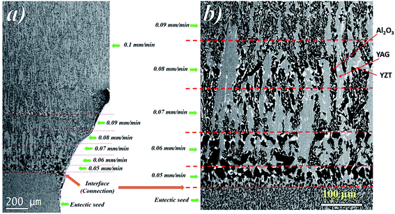
The sequence of microstructure formation in the eutectic composition is shown in Fig. 8 for one experimental run. The same results were observed for the other experimental runs. After the connection step through eutectic seed, a planar front was formed (Fig. 8a). The mechanism of the formation of the eutectic microstructure depends on the shape of the solidification front, which depends on the pulling rate. At low pulling rate (v ≤ 0.05 mm min−1), at the beginning of the solidification, since the melting temperatures of Al2O3 (2050 °C), YAG (1950 °C), and ZrO2 (2715 °C) are higher than the eutectic temperature (1750 °C), solute diffusion between the phases controls the melting of the eutectic microstructure. The first step of the growth (v = 0.05 mm min−1) shows mainly YAG platelets oriented along the solidification direction embedded in the continuous Al2O3-host (dark phase). The inter-lamellar eutectic average spacing (λ) is large (≈25 μm). ZrO2 is rejected in the liquid, only a little amount of irregular ZrO2 (light phase) is imbedded in the YAG phase (Fig. 8b). Under low pulling rate, ZrO2 segregation is observed and alumina matrix is free of the ZrO2 phase. This phenomenon is similar to the segregation of rare earth dopants (Nd, Ce) in laser and scintillating YAG single crystal growth.73,74 At the first step of the growth, the solidification process is close to the Al2O3–YAG binary eutectic system.35,75 By increasing the pulling rate (v > 0.07 mm min−1), most of the ZrO2 accumulated in the interface start to nucleate in the eutectic. When the inter-lamellar spacing (λ) increases to reach the largest value (25 μm), the solidification front is destabilized. This phenomenon allows the microstructure to adapt to the interface instabilities. Some YAG lamellas are divided into one and two lamellas to catch up with the minimum supercooling conditions for the coupled eutectic growth. As it is observed in Fig. 9, the new YAG lamella will, therefore, converge towards another lamella of the same phase to reach equilibrium of the eutectic microstructure. By increasing the pulling rate (v > 0.08 mm min−1), the distance between YAG lamellas decreases, and the temperature at the interface increases due to the decrease in ZrO2 rejection in the melt. In such conditions, the solidification interface shape continuously changes, especially close to the periphery of the meniscus, causing a strong thermal gradient affecting the eutectic microstructure and the morphology. The germination difficulties of the ZrO2 phase could be the cause of its decoupled growth from the YAG and Al2O3 phases. As it is shown in Fig. 8, there is a delay in the germination of the ZrO2 phase compared to that of the other two phases. The pulling rate gradually increases at the beginning of the solidification. The low pulling speed (0.05 mm min−1) at the start of the connection does not provide enough supercooling in the ZrO2 phase to nucleate. The ZrO2 phase only germinates 200 μm after connection. The delay and the difficulty of ZrO2 germination can be attributed to the strongly faceted interfaces of this eutectic.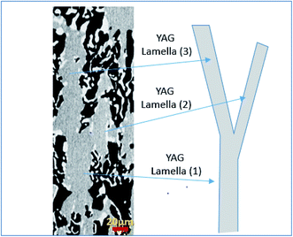 | ||
| Fig. 9 YAG lamella divided into two lamellas (YAG lamella (1) → YAG lamella (2) + YAG lamella (3)) to catch up with the minimum supercooling conditions for the coupled eutectic growth. | ||
In fact, heterogeneous nucleation on a faceted plane is more difficult than the germination in steps because the germination energy barrier is greater.76 The interface is observed to become concave at 0.08 mm min−1, giving the critical conditions for the planar interface instability.
Three parameters control the coupled eutectic growth: the rate of solidification (v), the thermal gradient (G) along the direction of crystallization linked to the elaboration method and the deviation from the eutectic composition (ΔC). The microstructure of (NE01 → NE05) samples consists of dendrites, colony phases and eutectic microstructure domains. The instability is linked to the off eutectic composition. In this case, the liquidus temperature is higher than the temperature of the eutectic and the excess primary phase is more supercooled and tends to grow faster than the composite forming faceted crystals (YAG, Al2O3) or dendrites. For a deviation from the eutectic composition, it is possible to increase the rate of solidification to approach the eutectic microstructure. Conversely, it is possible to obtain colonies, dendrites and even geometrical pattern microstructures with exactly the eutectic composition if the solidification rate is high enough.
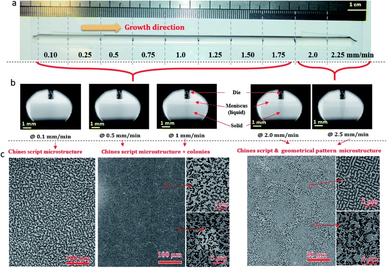
The change in the solidification rate from 0.1 mm min−1 to 2.25 mm min−1 (Fig. 10a) led microscopically to the change in the flatness of the solidification interface and its destabilization (Fig. 10b). By taking into account the thermal gradient (G) and the growth rate (v), the interface stability is determined by the critical ratio (G/v)c. The colony microstructures occur when this ratio is below the critical limit. At low pulling rate (0.1 mm min−1), as shown in Fig. 10b, a flat interface is observed with a meniscus length of around 386 ± 20 μm. However, as the pulling rate is increased, the interface shape is destabilized and the meniscus length increases to reach 892 ± 20 μm at 1 mm min−1 (Fig. 10b) and form few colony structures not observed at low pulling rate. The amplitude of the thermal gradient (G) limits directly the maximum pulling rate at which growing can be realized without unwanted breakdown of the flat liquid–solid interface and the formation of a colony microstructure. A change in the morphology at the center of the colonies appears for a solidification rate higher than 1.75 mm min−1 (Fig. 10c).
Fig. 10c shows the geometrical pattern microstructure formed at the center of the colonies under solidification rates of 2 and 2.25 mm min−1. Then, approaching the edge of the colonies, the Chinese script microstructure is formed because the solidification rate is slower. The phases have a very angular appearance. It is important to mention that the microstructures and the morphology are strongly connected to the growth parameters. Using the same solidification conditions, the system is reproducible.
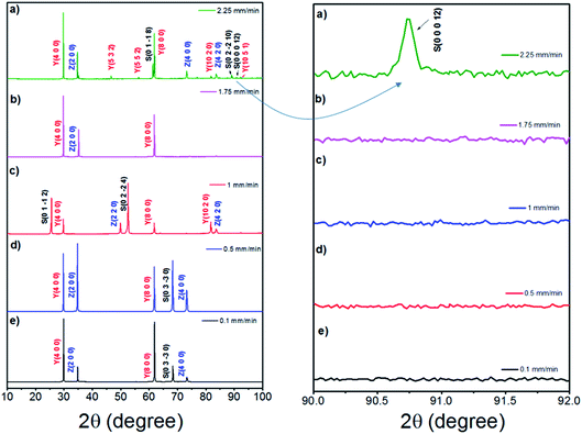
The crystallographic study (Fig. 11) of the samples solidified at high pulling rate (≥1.75 mm min−1) reveals a change in the growth orientation of Al2O3. A new (0 0 0 12) sapphire direction appears corresponding to c-axis.
The change in growth direction and the appearance of this type of microstructure can be connected to the anisotropy of thermal conductivity of a phase which is disoriented according to the most conductive direction of growth to evacuate latent heat. There is indeed anisotropy within alumina, the direction of growth 〈0001〉 is more conductive. This observation could be a hypothesis to explain the appearance of this microstructure at high pulling rate (2.25 mm min−1, Fig. 10c). In addition, the microstructure formed by zirconia and alumina is reminiscent of that of the fibrous binary eutectic of these two phases.29,36
The ratios of the area fractions of zirconia to alumina from a Chinese script region to a geometric pattern region were estimated. It is 0.35% when the microstructure is Chinese script and 0.29% when the microstructure is geometrical pattern. This value is very close to the condition for obtaining a fibrous microstructure in the Al2O3–ZrO2 eutectic system.77
Similar observations were made in the case of the Al2O3–GdAlO3–ZrO2 ternary eutectic system with respect to the changes in the surface fraction ratios.78 The variation in the area fraction from the center to the edge of the colonies could be assigned to a change in composition.
Indeed, Song et al.50 during solidification outside the eutectic point at a given rate, obtained the geometrical pattern microstructure by adding zirconia. This hypothesis could suggest that zirconia is at the origin of the interface destabilization and, therefore, of the colony formation.
4. Conclusion
The solidification studies in the Al2O3–YAG–ZrO2 eutectic system show the eutectic microstructures to consist of lamellas of YAG and ZrO2:Y precipitates in an Al2O3 matrix. The grains are chemically homogeneous and have no impurities. Colony growth is found to be involved in all the samples solidified at high pulling rate (v ≥ 0.5 mm min−1), and it results from interface destabilization and heterogeneity distribution of the ZrO2:Y phase. The rate of solidification also affects the crystallography growth direction of this ternary system. Therefore, the interface shape has to compete with the growth anisotropy in order to stabilize the optimum crystallographic directions. In addition to colony formation, cells and dendrites are observed when the samples are solidified outside the eutectic point.The Chinese script → geometrical pattern microstructural transition has been observed at high pulling rate (v > 1.75 mm min−1) and can be connected to the thermal anisotropy of the Al2O3 phase, which causes a rotation of this phase to facilitate heat release at high speed. In terms of understanding this solidification, the discontinuity of the ZrO2:Y phase, its rejection at the solidification interface, and, therefore, the difficulty of germination confirm the difficulties to control the solidification of this system. The morphology of the microstructure and the crystallography of this system suggest a non-simultaneous growth of the three eutectic phases, the zirconia phase probably solidifying behind the YAG and Al2O3 phases.
Conflicts of interest
There are no conflicts to declare.Acknowledgements
The authors acknowledge the French MAT&PRO ANR program “CiNATRA” ref: ANR-12-RMNP-0008 for financial support. The Authors thank Mesta project and the help of Mr Sébastien Joulie and Etienne Snoeck from CEMES-CNRS laboratory (Toulouse) for TEM investigation. We also thank M. Podgorski ODGORSKI from SAFRAN for his cooperation and assistance. We thank our collaborators at RSA le Rubis company (J. Navizet), ONERA (Michel Parlier, Marie-Hélène Ritti, Roger Valle), SIMAP Grenoble (T. Duffar, M. Cherif) and ICMPE-Thiais (L. Londaitzbehere, L. Mazerolles) for the exchange and discussion. The authors express their gratitude to Dr A. Nehari and Dr G. Alombert-Goget for their great collaboration and exchange. Thanks to Dr H. Cabane and M. Dumortier from Cristalinnov for their technical assistance and polishing samples.References
- S. Park and H. J. Yoon, New Approach for Large-Area Thermoelectric Junctions with a Liquid Eutectic Gallium–Indium Electrode, Nano Lett., 2018, 18, 7715–7718, DOI:10.1021/acs.nanolett.8b03404.
- B. J. Carey, J. Z. Ou, R. M. Clark, K. J. Berean, A. Zavabeti, A. S. R. Chesman, S. P. Russo, D. W. M. Lau, Z.-Q. Xu, Q. Bao, O. Kavehei, B. C. Gibson, M. D. Dickey, R. B. Kaner, T. Daeneke and K. Kalantar-Zadeh, Wafer-scale two-dimensional semiconductors from printed oxide skin of liquid metals, Nat. Commun., 2017, 8, 14482, DOI:10.1038/ncomms14482.
- N. Syed, A. Zavabeti, K. A. Messalea, E. Della Gaspera, A. Elbourne, A. Jannat, M. Mohiuddin, B. Y. Zhang, G. Zheng, L. Wang, S. P. Russo, D. Esrafilzadeh, C. F. McConville, K. Kalantar-Zadeh and T. Daeneke, Wafer-Sized Ultrathin Gallium and Indium Nitride Nanosheets through the Ammonolysis of Liquid Metal Derived Oxides, J. Am. Chem. Soc., 2019, 141, 104–108, DOI:10.1021/jacs.8b11483.
- I. D. Tevis, L. B. Newcomb and M. Thuo, Synthesis of Liquid Core–Shell Particles and Solid Patchy Multicomponent Particles by Shearing Liquids Into Complex Particles (SLICE), Langmuir, 2014, 30, 14308–14313, DOI:10.1021/la5035118.
- F. C. Simeone, H. J. Yoon, M. M. Thuo, J. R. Barber, B. Smith and G. M. Whitesides, Defining the Value of Injection Current and Effective Electrical Contact Area for EGaIn-Based Molecular Tunneling Junctions, J. Am. Chem. Soc., 2013, 135, 18131–18144, DOI:10.1021/JA408652H.
- H. Song, T. Kim, S. Kang, H. Jin, K. Lee and H. J. Yoon, Ga-Based Liquid Metal Micro/Nanoparticles: Recent Advances and Applications, Small, 2020, 16, 1903391, DOI:10.1002/smll.201903391.
- G. D. Kong, J. Jin, M. Thuo, H. Song, J. F. Joung, S. Park and H. J. Yoon, Elucidating the Role of Molecule–Electrode Interfacial Defects in Charge Tunneling Characteristics of Large-Area Junctions, J. Am. Chem. Soc., 2018, 140, 12303–12307, DOI:10.1021/jacs.8b08146.
- Y. Waku, S. Sakata, A. Mitani, K. Shimizu and M. Hasebe, Temperature dependence of flexural strength and microstructure of Al2O3/Y3Al5O12/ZrO2 ternary melt growth composites, J. Mater. Sci., 2002, 37, 2975–2982, DOI:10.1023/A:1016073115264.
- J. M. Calderon-Moreno and M. Yoshimura, Al2O3–Y3Al5O12(YAG)–ZrO2 ternary composite rapidly solidified from the eutectic melt, J. Eur. Ceram. Soc., 2005, 25, 1365–1368, DOI:10.1016/j.jeurceramsoc.2005.01.012.
- J. H. Lee, A. Yoshikawa, H. Kaiden, K. Lebbou, T. Fukuda, D. H. Yoon and Y. Waku, Microstructure of Y2O3 doped Al2O3/ZrO2 eutectic fibers grown by the micro-pulling-down method, J. Cryst. Growth, 2001, 231, 179–185, DOI:10.1016/S0022-0248(01)01451-8.
- W. J. Minford, R. C. Bradt and V. S. Stubican, Crystallography and Microstructure of Directionally Solidified Oxide Eutectics, J. Am. Ceram. Soc., 1979, 62, 154, DOI:10.1111/j.1151-2916.1979.tb19043.x.
- C. O. Hulse and J. A. Batt, The Effect of Eutectic Microstructures on the Mechanical Properties of Ceramic Oxides, United Aircraft Research Labs, East Hartford CT, 1974, https://apps.dtic.mil/sti/citations/AD0781995 Search PubMed.
- V. S. Stubican and R. C. Bradt, Eutectic Solidification in Ceramic Systems, Annu. Rev. Mater. Sci., 1981, 11, 267–297, DOI:10.1146/annurev.ms.11.080181.001411.
- A. Julian-Jankowiak, R. Valle and M. Parlier, Potential of innovative ceramics for turbine applications, Mater. High Temp., 2016, 33, 578–585, DOI:10.1080/09603409.2016.1166686.
- K. Hirano, Application of eutectic composites to gas turbine system and fundamental fracture properties up to 1700 °C, J. Eur. Ceram. Soc., 2005, 25, 1191–1199, DOI:10.1016/j.jeurceramsoc.2005.01.003.
- C. Oelgardt, J. Anderson, J. G. Heinrich and G. L. Messing, Sintering, microstructure and mechanical properties of Al2O3–Y2O3–ZrO2 (AYZ) eutectic composition ceramic microcomposites, J. Eur. Ceram. Soc., 2010, 30, 649–656, DOI:10.1016/j.jeurceramsoc.2009.09.011.
- T. Nagira, H. Yasuda, S. Takeshima, T. Sakimura, Y. Waku and K. Uesugi, Chain structure in the unidirectionally solidified Al2O3–YAG–ZrO2 eutectic composite, J. Cryst. Growth, 2009, 311, 3765–3770, DOI:10.1016/j.jcrysgro.2009.05.004.
- J. Yi, A. S. Argon and A. Sayir, Creep resistance of the directionally solidified ceramic eutectic of Al2O3/c-ZrO2(Y2O3): experiments and models, J. Eur. Ceram. Soc., 2005, 25, 1201–1214, DOI:10.1016/j.jeurceramsoc.2005.01.018.
- L. Mazerolles, L. Perriere, S. Lartigue-Korinek and M. Parlier, Creep behavior and related structural defects in Al2O3–Ln2O3 (ZrO2) directionally solidified eutectics (Ln = Gd, Er, Y), J. Eur. Ceram. Soc., 2011, 31, 1219–1225, DOI:10.1016/j.jeurceramsoc.2010.07.040.
- D. Viechnicki and F. Schmid, Eutectic solidification in the system Al2O3/Y3Al5O12, J. Mater. Sci., 1969, 4, 84–88, DOI:10.1007/BF00555053.
- F. Schmid and D. Viechnicki, Oriented eutectic microstructures in the system Al2O3/ZrO2, J. Mater. Sci., 1970, 5, 470–473, DOI:10.1007/BF00556032.
- Y. Waku, N. Nakagawa, T. Wakamoto, H. Ohtsubo, K. Shimizu and Y. Kohtoku, High-temperature strength and thermal stability of a unidirectionally solidified Al2O3/YAG eutectic composite, J. Mater. Sci., 1998, 33, 1217–1225, DOI:10.1023/A:1004377626345.
- V. A. Borodin, V. V. Sidorov, T. A. Steriopolo and V. A. Tatarchenko, Variable shaping growth of refractory oxide shaped crystals, J. Cryst. Growth, 1987, 82, 89–94, DOI:10.1016/0022-0248(87)90169-2.
- L. Carroz and T. Duffar, Tuning the sapphire EFG process to the growth of Al2O3/YAG/ZrO2:Y eutectic, J. Cryst. Growth, 2018, 489, 5–10, DOI:10.1016/j.jcrysgro.2018.02.029.
- L. Carroz, Etude et mise en oeuvre d'un procédé de préformage d'un alliage eutectique d'oxydes, These de doctorat, Université Grenoble Alpes (ComUE), 2016, https://www.theses.fr/2016GREAI070, accessed 23 September 2020.
- V. A. Borodin, M. Y. Starostin and T. N. Yalovets, Structure and related mechanical properties of shaped eutectic Al2O3–ZrO2(Y2O3) composites, J. Cryst. Growth, 1990, 104, 148–153, DOI:10.1016/0022-0248(90)90324-E.
- L. Mazerolles, L. Perriere, S. Lartigue-Korinek, N. Piquet and M. Parlier, Microstructures, crystallography of interfaces, and creep behavior of melt-growth composites, J. Eur. Ceram. Soc., 2008, 28, 2301–2308, DOI:10.1016/j.jeurceramsoc.2008.01.014.
- M. C. Mesa, S. Serrano-Zabaleta, P. B. Oliete and A. Larrea, Microstructural stability and orientation relationships of directionally solidified Al2O3–Er3Al5O12–ZrO2 eutectic ceramics up to 1600 °C, J. Eur. Ceram. Soc., 2014, 34, 2071–2080, DOI:10.1016/j.jeurceramsoc.2013.11.011.
- J. I. Peña, R. I. Merino, N. R. Harlan, A. Larrea, G. F. de la Fuente and V. M. Orera, Microstructure of Y2O3 doped Al2O3–ZrO2 eutectics grown by the laser floating zone method, J. Eur. Ceram. Soc., 2002, 22, 2595–2602, DOI:10.1016/S0955-2219(02)00121-8.
- A. Sayir and S. C. Farmer, The effect of the microstructure on mechanical properties of directionally solidified Al2O3/ZrO2(Y2O3) eutectic, Acta Mater., 2000, 48, 4691–4697, DOI:10.1016/S1359-6454(00)00259-7.
- V. M. Orera, J. I. Peña, P. B. Oliete, R. I. Merino and A. Larrea, Growth of eutectic ceramic structures by directional solidification methods, J. Cryst. Growth, 2012, 360, 99–104, DOI:10.1016/j.jcrysgro.2011.11.056.
- A. Laidoune, K. Lebbou, D. Bahloul, M. Smadi and M. Zereg, Yttria stabilized Al2O3–ZrO2 eutectic crystal fibers grown by the laser heated pedestal growth (LHPG) method, Opt. Mater., 2010, 32, 731–734, DOI:10.1016/j.optmat.2010.02.003.
- A. Koh, W. Hwang, P. Y. Zavalij, S. Chun, G. Slipher and R. Mrozek, Solidification and melting phase change behavior of eutectic gallium–indium–tin, Materialia, 2019, 8, 100512, DOI:10.1016/j.mtla.2019.100512.
- A. Yoshikawa, B. M. Epelbaum, K. Hasegawa, S. D. Durbin and T. Fukuda, Microstructures in oxide eutectic fibers grown by a modified micro-pulling-down method, J. Cryst. Growth, 1999, 205, 305–316, DOI:10.1016/S0022-0248(99)00265-1.
- B. M. Epelbaum, A. Yoshikawa, K. Shimamura, T. Fukuda, K. Suzuki and Y. Waku, Microstructure of Al2O3/Y3Al5O12 eutectic fibers grown by μ-PD method, J. Cryst. Growth, 1999, 198–199, 471–475, DOI:10.1016/S0022-0248(98)01052-5.
- A. Yoshikawa, K. Hasegawa, T. Fukuda, K. Suzuki and Y. Waku, Growth and Diameter Control of Al2O3/Y3Al5O12, Euteciic Fiber by Micro-Pullingdown Method and its High Temperature Strngth and Thermal Stability, in 23rd Annual Conference on Composites, Advanced Ceramics, Materials, and Structures: B: Ceramic Engineering and Science Proceedings, John Wiley & Sons, Ltd, 2008, pp. 275–282, DOI:10.1002/9780470294574.ch32.
- J. H. Lee, A. Yoshikawa, T. Fukuda and Y. Waku, Growth and characterization of Al2O3/Y3Al5O12/ZrO2 ternary eutectic fibers, J. Cryst. Growth, 2001, 231, 115–120, DOI:10.1016/S0022-0248(01)01375-6.
- T. Fukuda, P. Rudolph and S. Uda, Fiber Crystal Growth from the Melt, Springer Science & Business Media, 2004 Search PubMed.
- O. Benamara, M. Cherif, T. Duffar and K. Lebbou, Microstructure and crystallography of Al2O3–Y3Al5O12–ZrO2 ternary eutectic oxide grown by the micropulling down technique, J. Cryst. Growth, 2015, 429, 27–34, DOI:10.1016/j.jcrysgro.2015.07.020.
- O. Benamara and K. Lebbou, Shaped ceramic eutectic plates grown from the melt and their properties, J. Cryst. Growth, 2016, 449, 67–74, DOI:10.1016/j.jcrysgro.2016.05.046.
- S. M. Lakiza and L. M. Lopato, Stable and Metastable Phase Relations in the System Alumina–Zirconia–Yttria, J. Am. Ceram. Soc., 1997, 80, 893–902, DOI:10.1111/j.1151-2916.1997.tb02919.x.
- M. Cherif, T. Duffar, L. Carroz, P. Lhuissier and E. Bautista-Quisbert, On the growth and structure of Al2O3–Y3Al5O12–ZrO2:Y solidified eutectic, J. Eur. Ceram. Soc., 2020, 40, 3172–3180, DOI:10.1016/j.jeurceramsoc.2020.03.025.
- J. I. Peña, M. Larsson, R. I. Merino, I. de Francisco, V. M. Orera, J. LLorca, J. Y. Pastor, A. Martín and J. Segurado, Processing, microstructure and mechanical properties of directionally-solidified Al2O3–Y3Al5O12–ZrO2 ternary eutectics, J. Eur. Ceram. Soc., 2006, 26, 3113–3121, DOI:10.1016/j.jeurceramsoc.2005.11.005.
- N. Piquet, Microstructures interconnectées dans des eutectiques à base d'oxydes réfractaires élaborés par solidification dirigée, These de doctorat, Paris, 12, 2006, http://www.theses.fr/2006PA120005, accessed 30 September 2020.
- H. Su, J. Zhang, L. Liu and H. Fu, Microstructure and mechanical properties of a directionally solidified Al2O3/Y3Al5O12/ZrO2 hypoeutectic in situ composite, Compos. Sci. Technol., 2009, 69, 2657–2667, DOI:10.1016/j.compscitech.2009.08.007.
- H. J. Su, J. Zhang, Y. F. Deng, L. Liu and H. Z. Fu, Growth and characterization of nanostructured Al2O3/YAG/ZrO2 hypereutectics with large surfaces under laser rapid solidification, J. Cryst. Growth, 2010, 312, 3637–3641, DOI:10.1016/j.jcrysgro.2010.09.032.
- H. Su, J. Zhang, J. Yu, L. Liu and H. Fu, Rapid solidification and fracture behavior of ternary metastable eutectic Al2O3/YAG/YSZ in situ composite ceramic, Mater. Sci. Eng., A, 2011, 528, 1967–1973, DOI:10.1016/j.msea.2010.11.046.
- H. Su, J. Zhang, K. Song, L. Liu and H. Fu, Investigation of the solidification behavior of Al2O3/YAG/YSZ ceramic in situ composite with off-eutectic composition, J. Eur. Ceram. Soc., 2011, 31, 1233–1239, DOI:10.1016/j.jeurceramsoc.2010.06.011.
- F. J. Ester, A. Larrea and R. I. Merino, Processing and microstructural study of surface laser remelted Al2O3–YSZ–YAG eutectic plates, J. Eur. Ceram. Soc., 2011, 31, 1257–1268, DOI:10.1016/j.jeurceramsoc.2010.08.016.
- K. Song, J. Zhang, X. Lin, L. Liu and W. Huang, Microstructure and mechanical properties of Al2O3/Y3Al5O12/ZrO2 hypereutectic directionally solidified ceramic prepared by laser floating zone, J. Eur. Ceram. Soc., 2014, 34, 3051–3059, DOI:10.1016/j.jeurceramsoc.2014.04.033.
- X. Fu, G. Chen, Y. Zu, J. Luo and W. Zhou, Microstructure refinement approaches of melt-grown Al2O3/YAG/ZrO2 eutectic bulk, Ceram. Int., 2013, 39, 7445–7452, DOI:10.1016/j.ceramint.2013.02.089.
- K. Song, J. Zhang, X. Jia, H. Su, L. Liu and H. Fu, Longitudinal cross-section microstructure of growth striation in Al2O3/Y3Al5O12/ZrO2 directionally solidified eutectic ceramic prepared by laser floating zone, J. Eur. Ceram. Soc., 2013, 33, 1123–1128, DOI:10.1016/j.jeurceramsoc.2012.12.003.
- E. L. Courtright, J. S. Haggerty and J. Sigalovsky, Controlling Microstructures in ZrO2(Y2O3)–Al2O3 Eutectic Fibers, in Proceedings of the 17th Annual Conference on Composites and Advanced Ceramic Materials: Ceramic Engineering and Science Proceedings, John Wiley & Sons, Ltd, 2008, pp. 671–681, DOI:10.1002/9780470314180.ch92.
- N. R. Harlan, R. I. Merino, J. I. Peña, A. Larrea, V. M. Orera, C. González, P. Poza and J. LLorca, Phase Distribution and Residual Stresses in Melt-Grown Al2O3–ZrO2(Y2O3) Eutectics, J. Am. Ceram. Soc., 2002, 85, 2025–2032, DOI:10.1111/j.1151-2916.2002.tb00399.x.
- H. M. Kandil, J. D. Greiner and J. F. Smith, Single-Crystal Elastic Constants of Yttria-Stabilized Zirconia in the Range 20° to 700 °C, J. Am. Ceram. Soc., 1984, 67, 341–346, DOI:10.1111/j.1151-2916.1984.tb19534.x.
- J. J. Sha, S. Ochiai, H. Okuda, Y. Waku, N. Nakagawa, A. Mitani, M. Sato and T. Ishikawa, Residual stresses in YAG phase in directionally solidified eutectic Al2O3/YAG ceramic composite estimated by X-ray diffraction, J. Eur. Ceram. Soc., 2008, 28, 2319–2324, DOI:10.1016/j.jeurceramsoc.2008.01.018.
- J. LLorca and V. M. Orera, Directionally solidified eutectic ceramic oxides, Prog. Mater. Sci., 2006, 51, 711–809, DOI:10.1016/j.pmatsci.2005.10.002.
- M. Cherif, Croissance de la céramique eutectique Al2O3–YAG–ZrO2:Y et étude de la microstructure Chinese Script, Phd thesis, Université Grenoble Alpes, 2016, https://tel.archives-ouvertes.fr/tel-01586458, accessed 23 September 2020.
- L. Londaitzbehere, Céramiques eutectiques oxydes à microstructure interconnectée préparées par solidification dirigée: élaboration, microstructure, mécanismes de déformation par fluage et réactivité en présence de vapeur d'eau, Phd thesis, Université Paris-Est, 2016, https://tel.archives-ouvertes.fr/tel-01562283, accessed 23 September 2020.
- J. Lefèvre, Contribution à l’étude de différentes modifications structurales des phases de type fluorine dans les systèmes à base de zircone ou d’oxyde de hafnium, Ann. Chim., 1963, 8, 117–149 Search PubMed.
- J. A. Krogstad, M. Lepple, Y. Gao, D. M. Lipkin and C. G. Levi, Effect of Yttria Content on the Zirconia Unit Cell Parameters, J. Am. Ceram. Soc., 2011, 94, 4548–4555, DOI:10.1111/j.1551-2916.2011.04862.x.
- R. P. Ingel and D. Lewis III, Lattice Parameters and Density for Y2O3-Stabilized ZrO2, J. Am. Ceram. Soc., 1986, 69, 325–332, DOI:10.1111/j.1151-2916.1986.tb04741.x.
- F. Hund, Die Fluoritphase im System ZrO2–CaO: Ihre Fehlordnung und das Auftreten elektrischer Leitfähigkeit, Z. Phys. Chem., 1952, 199, 142–151, DOI:10.1515/zpch-1952-19912.
- S.-M. Ho, On the structural chemistry of zirconium oxide, Mater. Sci. Eng., 1982, 54, 23–29, DOI:10.1016/0025-5416(82)90026-X.
- Al2O3 PDF file number: 04-007-4873, (n.d.).
- Y3Al5O12 PDF file number: 04-007-2667, (n.d.).
- H. Yasuda, I. Ohnaka, Y. Mizutani, T. Morikawa, S. Takeshima, A. Sugiyama, Y. Waku, A. Tsuchiyama, T. Nakano and K. Uesugi, Three-dimensional observation of the entangled eutectic structure in the Al2O3–YAG system, J. Eur. Ceram. Soc., 2005, 25, 1397–1403, DOI:10.1016/j.jeurceramsoc.2005.01.019.
- X. Fu, G. Chen, Y. Zu, J. Luo and W. Zhou, Microstructure refinement of melt-grown Al2O3/YAG/ZrO2 eutectic composite by a new method: melt superheating treatment, Scr. Mater., 2013, 68, 731–734, DOI:10.1016/j.scriptamat.2013.01.009.
- L. Mazerolles, N. Piquet, M.-F. Trichet, L. Perrière, D. Boivin and M. Parlier, New microstructures in ceramic materials from the melt for high temperature applications, Aerosp. Sci. Technol., 2008, 12, 499–505, DOI:10.1016/j.ast.2007.12.002.
- L. Mazerolles, D. Michel and R. Portier, Interfaces in Oriented Al2O3–ZrO2 (Y2O3) Eutectics, J. Am. Ceram. Soc., 1986, 69, 252–255, DOI:10.1111/j.1151-2916.1986.tb07419.x.
- X. Wang, Y. Zhong, Q. Sun, D. Qi, F. Yan, Q. Xian, D. Wang, K. Du and J. Wang, Competitive growth of Al2O3/YAG/ZrO2 eutectic ceramics during directional solidification: effect of interfacial energy, J. Am. Ceram. Soc., 2019, 102, 2176–2186, DOI:10.1111/jace.16057.
- J. H. Lee, A. Yoshikawa, Y. Murayama, Y. Waku, S. Hanada and T. Fukuda, Microstructure and mechanical properties of Al2O3/Y3Al5O12/ZrO2 ternary eutectic materials, J. Eur. Ceram. Soc., 2005, 25, 1411–1417, DOI:10.1016/j.jeurceramsoc.2005.01.034.
- K. Lebbou, A. Brenier, O. Tillement, J. Didierjean, F. Balembois, P. Georges, D. Perrodin and J. M. Fourmigue, Long (111)-oriented Y3Al5O12:Nd3+ single crystal fibers grown by modified micro-pulling down technology for optical characterization and laser generation, Opt. Mater., 2007, 30, 82–84, DOI:10.1016/j.optmat.2006.11.025.
- O. Sidletskiy, K. Lebbou, D. Kofanov, V. Kononets, I. Gerasymov, R. Bouaita, V. Jary, R. Kucerkova, M. Nikl, A. Polesel, K. Pauwels and E. Auffray, Progress in fabrication of long transparent YAG:Ce and YAG:Ce,Mg single crystalline fibers for HEP applications, CrystEngComm, 2019, 21, 1728–1733, 10.1039/C8CE01781F.
- K. Hasegawa, A. Yoshikawa, S. D. Durbin, B. M. Epellbaum, T. Fukuda and Y. Waku, Microstructure and high temperature mechanical properties of sapphire/R–Al–O(R = Y, Gd, Er, Ho, Dy) eutectic fibers grown by micro-pulling-down method, J. Korean Cryst. Growth Cryst. Technol., 1999, 9, 403–418 Search PubMed.
- J. H. Perepezko and M. J. Uttormark, Nucleation-Controlled Solidification Kinetics, Metall. Mater. Trans. A, 1996, 27, 533–547, DOI:10.1007/BF02648944.
- W. J. Minford, R. C. Bradt and V. S. Stubican, Crystallography and Microstructure of Directionally Solidified Oxide Eutectics, J. Am. Ceram. Soc., 1979, 62, 154, DOI:10.1111/j.1151-2916.1979.tb19043.x.
- W. Ma, J. Zhang, H. Su, Q. Ren, B. Yao, L. Liu and H. Fu, Microstructure transformation from irregular eutectic to complex regular eutectic in directionally solidified Al2O3/GdAlO3/ZrO2 ceramics by laser floating zone melting, J. Eur. Ceram. Soc., 2016, 36, 1447–1454, DOI:10.1016/j.jeurceramsoc.2015.12.023.
| This journal is © The Royal Society of Chemistry 2021 |

