 Open Access Article
Polyaniline nano-needles into electrospun bio active fibres support in vitro astrocyte response†
Emanuela Saracino*a,
Simona Zuppolinib,
Vincenzo Guarino *b,
Valentina Benfenati
 a,
Anna Borriello*b,
Roberto Zambonia and
Luigi Ambrosiob
aInstitute of Organic Synthesis and Photoreactivity (ISOF), National Research Council of Italy, via Gobetti, 101, 40129, Bologna, Italy. E-mail: emanuela.saracino@isof.cnr.it
bInstitute for Polymers, Composites and Biomaterials (IPCB), National Research Council of Italy, Mostra d'Oltremare, Pad. 20, V. le J. F. Kennedy 54, Naples, Italy. E-mail: vguarino@unina.it; vincenzo.guarino@cnr.it; borriell@unina.it
First published on 18th March 2021
Abstract
Recent studies have proposed that the bioelectrical response of glial cells, called astrocytes, currently represents a key target for neuroregenerative purposes. Here, we propose the fabrication of electrospun nanofibres containing gelatin and polyaniline (PANi) synthesized in the form of nano-needles (PnNs) as electrically conductive scaffolds to support the growth and functionalities of primary astrocytes. We report a fine control of the morphological features in terms of fibre size and spatial distribution and fibre patterning, i.e. random or aligned fibre organization, as revealed by SEM- and TEM-supported image analysis. We demonstrate that the peculiar morphological properties of fibres – i.e., the fibre size scale and alignment – drive the adhesion, proliferation, and functional properties of primary cortical astrocytes. In addition, the gradual transmission of biochemical and biophysical signals due to the presence of PnNs combined with the presence of gelatin results in a permissive and guiding environment for astrocytes. Accordingly, the functional properties of astrocytes measured via cell patch-clamp experiments reveal that PnNs do not alter the bioelectrical properties of resting astrocytes, thus setting the scene for the use of PnN-loaded nanofibres as bioconductive platforms for interfacing astrocytes and controlling their bioelectrical properties.
1. Introduction
Recent studies have demonstrated that external electric field stimulation can accelerate nerve regeneration by supporting the exchange of information by neurons both in vitro and in vivo.1 This effect can be corroborated by the use of biocompatible polymers with electrically conductive properties, which can promote cell adhesion by a controlled transfer of electrical signals and by the administration of moderate currents that avoid killing nerve tissue and cells.1–4 In the last decade, several studies have investigated the use of electro-conductive materials as building blocks to design active interfaces between electronic and biological fields for various applicative uses (i.e., molecular targeting, biosensors, biocompatible scaffolds).5 Among them, electroactive polymers (EAPs) are emerging as a class of organic materials with intrinsic conductive properties, similar to those of metals and semiconductors, which can be accurately controlled by modifying chemical and physical surface properties in order to directly influence the charge mobility along the backbone of the polymer chain.6–8 In this context, polyaniline (PANi) is a widely recognized EAP that shows good biocompatibility, high environmental stability and switchable properties between conductive and resistive states in vitro.9 The peculiar chemistry of PANi, based on repeating units of aniline monomers with alternate single and double bonds, including phenyl rings with nitrogen atoms, promotes the formation of different oxidation states (e.g., emeraldine, nigranidine, and leucoemeraldine) with chemical/physical properties that are suitable to fight inflammatory response and support cell growth.10,11 According to recent studies, the biological response can be properly addressed as a function of the electronic properties of conjugated polymers, which are finely tuneable by manipulating topological (i.e., the structure of the polymer backbone) and/or chemical factors (i.e., nature/concentration of the dopant ions).7,10–13With respect to nerve regeneration, while several studies have demonstrated the favourable interaction of neuronal cells with PANi and PANi-loaded fibres, allowing for the regeneration of neurites and functional excitability in vitro and in vivo,12,14,15 studies are lacking on the effect of PANi on brain glial cells, called astrocytes. Astrocytes are cells in the central nervous system that are primarily involved in the regulation of the homeostatic balance of ions, water, and molecules in the extracellular space.16 Although they are incapable of action potential, astrocytes express ion channels and bioelectric properties17 with critical roles in brain cognitive functions such as learning and memory. Alteration in the morphology, cytoskeletal structure and ion channel function of astrocytes is implicated in acute and chronic pathologies.17 It is worth noting that the inflammatory response to brain and nerve implants is mainly driven by alteration in glial cells and in particular to astrogliosis reactions, which cause dramatic changes in astrocyte morphology, increased expression of glial fibrillar acid protein (GFAP) and loss of or alteration in the expression and function of ion channels.16–18
Despite their inability to generate action potential, astrocytes can respond to electrical, mechanical and topographical stimuli provided by nanostructured material interfaces and devices.18–20 However, nanostructured devices based on conductive substrates enable the recording of bioelectrical signals from primary differentiated astrocytes at a precise slow frequency. This evidence highlights the possibility and the need to generate glial interfaces that target structural and bioelectrical properties of astrocytes to induce signal promoting/supporting of neuroregenerative processes19 or functional recovery of neurons.21 Despite the rising interest in astrocytes in biomaterials design, a comprehensive study of the impact of conductive PANi biomaterials on the morphology, the cytoskeletal properties and above all on the ion channel function of astrocytes has never been reported. In this work, to address this lack of knowledge, we report the fabrication of a novel composite platform made of poly-ε-caprolactone (PCL) and embedded with gelatin and PnNs; it was fabricated via an electrospinning technique.
Electrospinning is the leading technology to fabricate fibrous scaffolds with random or aligned fibres that mimic the architecture of the extracellular matrix of natural tissues.20 In order to improve the biological response, the blending of synthetic polymers with natural proteins, i.e., collagen, gelatin, and zein, currently represents a consolidated strategy to impart selected biochemical cues that can more actively support in vitro cell interaction.22
Herein, electrically conductive nanocomposite platforms were obtained by embedding electro-conductive PANi into electrospun fibres, and the response of primary astrocytes grown on PANi nano-needles (PnNs) was evaluated in terms of adhesion, proliferation, morphology and bioelectrical activity.
2. Materials and methods
2.1 Materials
Poly-ε-caprolactone (PCL, Mn 45 kDa), bovine gelatin type B (gel ∼ 225 bloom) in powder form, chloroform (CHCl3), and 1,1,1,3,3,3-hexafluoro-2-propanol (HFiP) were all purchased from Sigma Aldrich (Italy). For the synthesis of PnNs, aniline, ammonium peroxy disulphate (APS), camphor sulphonic acid (CSA), and emeraldine base polyaniline (EB, Mw 10 kDa) were purchased from Sigma Aldrich (Italy). All chemicals were used as received without additional purification.The (as-prepared) nanofibres can be purified by centrifugation, a common solid–liquid separation technique. PNs were obtained in powder form after drying at 80 °C under vacuum. The dry powders of polyaniline were re-dispersed in HFIP by mild sonication. In order to validate the conductive properties of the PnNs, two-probe DC electrical resistance measurements were performed using a Signatone 1160 probe station connected to a picometer/voltage source meter (National Instrument) in ambient conditions. A custom cell was designed and realized in polytetrafluoroethylene (PTFE) to efficiently perform conductivity tests on these films.
In order to prevent surface current errors, the cell has an internal platinum circular electrode with a diameter of 10 mm and a guard ring placed at a distance of 0.5 cm. For these experiments, samples with different PCL/PnNs ratios (100/0, 99/1, 95/5, 90/10, and 80/20 wt/wt) were optimized to prepare thin casted films by solvent evaporation. As a control, EB-doped PANi samples (EBP) were prepared by doping of EB via CSA (50/50 wt/wt) and dissolution of the subsequent polymer in HFIP (6 × 10⁻³ M) at room temperature under magnetic stirring (2 h).
![[thin space (1/6-em)]](https://www.rsc.org/images/entities/char_2009.gif) :
:![[thin space (1/6-em)]](https://www.rsc.org/images/entities/char_2009.gif) 1 w/w ratio).
1 w/w ratio).Lastly, PnNs (5% wt with respect to the total polymer concentration) were added by gently stirring for a further 24 h. PnNs-loaded electrospun fibres were produced using electrospinning equipment (Nanon01, Mecc, Fukuoka, Japan) with an 18G needle and vertical configuration. Random and aligned fibres were collected on small glass discs (diameter 12 mm) fixed on a rotating drum (diameter 19 cm) for 1 h. All the parameters (i.e., flow rate, voltage, electrode distance, rotation speed) were optimized in order to obtain the best fibre morphology. As a control, electrospun fibres without PnNs were fabricated under the same processing conditions. The process parameters for all the electrospun fibres are summarized in Table 1. All the experiments were performed at room temperature within a range of relative humidity (RH) = 45–55%.
| Flow rate (ml h−1) | Voltage (kV) | Electrode distance (mm) | Rotation speed (rpm) | ||
|---|---|---|---|---|---|
| Random | CTR | 0.5 | 13 | 120 | 50 |
| PANI | |||||
| Aligned | CTR | 0.5 | 13 | 120 | 3000 |
| PANI | |||||
PnNs and PnNs-loaded fibres were analyzed by scanning electron microscopy (SEM; Quanta FEG 200, FEI, The Netherlands) in order to assess the morphology of the fibres. The specimens were sputter-coated with a Pd–Au nano layer (Emitech K550, Italy) and then observed under high vacuum conditions (10−5 mbar) at a low voltage electron emission (lower than 10 kV) to minimize beam invasiveness on the polymer matrices. The mean diameter of the fibres was calculated from selected SEM images (ca. 20 units) by using image analysis software (ImageJ freeware 1.52a) and reported as diameter distribution and mean value ± standard deviation.
2.2 In vitro studies
The fluorescein diacetate assay (FDA) and evaluation of the morphology of astrocytes grown on aligned −PANi and +PANi electrospun fibres was performed 24 h (1 DIV) and 96 h (4 DIV) from the re-plating of astrocytes on the substrates.23,24 A sequence of images (10 to 15 different fields for each sample) was taken using a Nikon TE 2000 inverted confocal microscope (40× objective). The orientation angle measurement of an individual cell was defined as previously described.25 Results were analysed using the ORIGIN-PRO (Microcal) program. All the immune fluorescence and confocal microscopy experiments on astrocytes plated on different samples were performed as previously described.26 The primary antibodies used were rabbit anti-vinculin (Life Technologies, Monza, Italy); anti GFAP (Sigma Aldrich); and donkey anti-rabbit Alexa Fluor 488-conjugated as a secondary antibody (1![[thin space (1/6-em)]](https://www.rsc.org/images/entities/char_2009.gif) :
:![[thin space (1/6-em)]](https://www.rsc.org/images/entities/char_2009.gif) 1000, Molecular Probes-Invitrogen). F-actin fibres were stained for phalloidin-TRITC (Sigma-Aldrich, Milan, Italy). Coverslips were mounted with Prolong Anti-Fade with DAPI (Molecular Probes-Invitrogen). The optical images were taken with a Nikon TSE 2000 inverted confocal microscope and a Photometrics camera (Crisel Instruments). Data were collected at least from three different experiments performed in triplicate. At least 15 images for each replica of a condition were analysed by ImageJ software. The focal adhesion (FA) point density was expressed as means ± SE of the number of vinculin contacts counted for each image (300 μm × 300 μm) and divided by the number of nuclei (blue staining) in the same image.
1000, Molecular Probes-Invitrogen). F-actin fibres were stained for phalloidin-TRITC (Sigma-Aldrich, Milan, Italy). Coverslips were mounted with Prolong Anti-Fade with DAPI (Molecular Probes-Invitrogen). The optical images were taken with a Nikon TSE 2000 inverted confocal microscope and a Photometrics camera (Crisel Instruments). Data were collected at least from three different experiments performed in triplicate. At least 15 images for each replica of a condition were analysed by ImageJ software. The focal adhesion (FA) point density was expressed as means ± SE of the number of vinculin contacts counted for each image (300 μm × 300 μm) and divided by the number of nuclei (blue staining) in the same image.
3. Results and discussion
3.1 PANi electrospun nanofibre fabrication and characterization
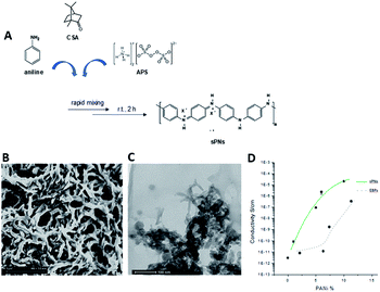
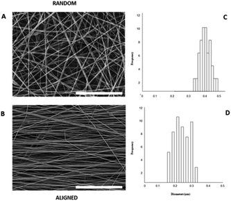
Herein, we propose the fabrication of nanocomposite fibres containing PnNs – namely polyaniline synthesized in the form of nano-needles that can transfer electrical signals to support the growth and functionalities of primary astrocytes, minimizing the cytotoxic effects. Indeed, the peculiar needle-like shape of the PnNs enables the formation of a percolative pathway of electrically conductive phases, drastically reducing the irrelative fraction into the fibre body. PnNs were endowed into bicomponent fibres obtained by blending PCL and gelatin, largely validated in terms of in vitro biodegradation and biomechanical and biocompatible response.27–29 The morphology of the PnNs was investigated by SEM and TEM with the support of image analysis. Fig. 1B and C show PnNs with diameters in a range from 50 to 100 nm and average lengths from hundreds of nanometres up to a few micrometres. Conductivity tests confirmed that the electrical conductivity of the PnNs equaled 0.05 S cm−1 in air and was not affected by the synthesis procedure, in comparison with previous data in literature.28 Moreover, it was demonstrated that the properties of the PnNs were significantly higher than those of the EBPs, as confirmed by the comparison of the conductivity curves of the PnNs and EBP-loaded films (Fig. 1D). As a function of the conductive phase content, the results demonstrated a higher attitude of charge transport of the dispersed PnNs with respect to EBPs at the same volume fraction. Indeed, in the case of low fractions of EBPs, the peculiar globular shape tends to promote more limited contacts due to a large average distance among adjacent conducting phases. Indeed, the EBPs fraction must reach a critical value to generate an adequate number of punctual bridges that are suitable to form a conductive path that can percolatively transfer the electrical signal. In the case of PnNs, the peculiar shape factor of the nano-needles allows more efficient support of the formation mechanism of the contact points, thus originating percolative conductive pathways in the presence of lower amounts of the conductive phases. Therefore, it was identified that the critical value for PnNs corresponded to 5 wt% (Fig. 1D), and this concentration was used to fabricate electrospun fibres to investigate the biological response with astrocytes. In Fig. 2A and B, SEM images of random and aligned PnNs-loaded electrospun fibres are reported. As for the fibre processing, HFIP was selected to greatly dissolve gelatin and PCL and promote a fine dispersion of PnNs into the solution. Moreover, the high polarity of HFIP allows strong interactions with the electric field, thus promoting remarkable jet stretching with low-concentrated solutions (i.e., 10% w/v).30,31 As a consequence, the fibres showed a narrowed distribution of sizes, with mean diameters in the submicrometric range, equal to 0.44 ± 0.07 μm (Fig. 2C). No relevant differences in fibre size and distribution can be recognized due to the presence of PnNs (+PANi) in comparison with the controls (−PANi), as investigated in previous work.27,32 Indeed, the presence of conductive phases mainly tends to promote the formation of free charges in solution; this helps stabilize the dispersion without altering the mechanism of fibre formation during the electrospinning process.8,33 Hence, the resulting PnNs-added fibres were beadless and homogeneously dispersed. A different effect was recognized in the case of aligned fibres fabricated by collecting fibres onto the surface of a rotating collector. In this case, the mechanical drawing due to the high rotating rates significantly influences the solvent evaporation, consequently reducing the final diameters of the fibres to 0.25 ± 0.04 μm (Fig. 2D). No relevant differences in the fibre diameters can be recognized with respect to the aligned fibres without the presence of PnNs.34 Instead, the PnNs mainly help promote a more efficient alignment of fibres due to the polarization of inherent charged groups of PANi in the solution, which tends to promote remarkable jet instabilities, i.e., the whipping effect.3.2 Effects of PANi electrospun nanofibre on the viability and morphology of primary astrocytes
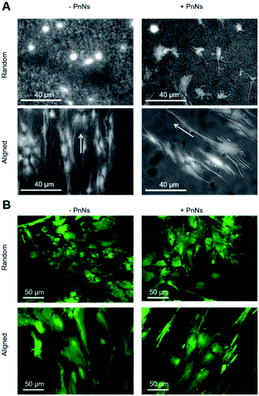
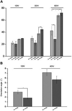
In order to determine the impact of PnNs on astrocyte adhesion and morphology in vitro, confluent primary rat cortical astrocytes were re-plated on random and aligned substrates of +PANi and −PANi used as controls. We report typical bright field images (Fig. 3A) and fluorescent images (Fig. 3B) of viable (green) astrocytes captured at 2 DIV and at 4 DIV, plated on random −PANi and +PANi (Fig. 3A and B, upper panels) and aligned −PANi and +PANi fibres (Fig. 3A and B, lower panels). Notably, the astrocytes on random substrates are polygonal, with a shape typically observed when the same type of culture is plated on PDL or on other biopolymers and bioorganic interfaces.25,26 On the other hand, astrocytes grown on aligned −PANi and +PANi fibres appear elongated and aligned with the orientation of the fibres (Fig. 3A and B, lower panel, white arrows).The bar plot reported in Fig. 4A shows the percentage of reduced AB with respect to the oxidized one; the value is proportional to the metabolic activity and, in turn, to the presence of viable cells. After 3 DIV, the viability value of +PANi samples was significantly higher compared to the value of aligned −PANi samples. A constant increase in cell viability was observed in −PANi and +PANi samples in both random and aligned conditions at 8 DIV. However, the cell proliferation rate was higher in both aligned −PnNs and +PnNs samples (ESI, S1†). The cells in the aligned samples with respect to random samples indicates that the topography of the nanostructure could positively impact cell survival. At 8 DIV, the presence of PnNs is associated with a higher cell viability only on the aligned samples.
The presence of PANi decreased the orientation angle at 1 DIV as well as at 4 DIV, indicating that the degree of alignment of cells is higher in the presence of the conductive polymer (Fig. 4B).
Astrocyte adhesion, growth and morphology can be altered or even driven by interactions with nanomaterials.18,20,26,27,35,36 With respect to electrospun nanofibres, previous data indicated that the topography is the major superficial clue driving adhesion and growth of astrocytes.25 Accordingly, in the present work, the aligned nanofibres display the best performance in terms of viability and growth of primary astrocytes over time. In addition, the presence of PnNs is associated with a higher viability of astrocytes, but only in the aligned samples. Different distributions or orientation patterns of PnNs in the aligned samples may account for the observed effect.
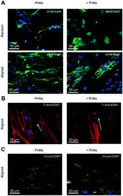
We next analyzed confocal imaging of immunostained cells, performed after 3 DIV, to give evidence of the comparable levels of the expression of glial fibrillar acid protein (GFAP), a well-known marker of the inflammatory reaction called astrogliosis, among cells grown on different samples (Fig. 5A, upper panel, random samples and Fig. 5A, lower panel, aligned samples). The typical images of phalloidin-stained cells reported in Fig. 5B show that astrocytes cultured on aligned −PANi and +PANi substrates express both stressed F actin fibres parallel to the pattern of −PANi fibres (Fig. 5B, white arrows).
Cells plated on random substrates (ESI S2†) displayed a disorganized structure of the F-actin fibres resembling those on PDL, as previously demonstrated.27 The vinculin fluorescent signal analyses on cells grown on aligned −PANi substrates (Fig. 5C, left panel) indicated patchy but marked expression of the protein at the boundaries of the astrocytes, while the vinculin expression of astrocytes plated on aligned +PANi was more mislocalized in the cell body (Fig. 3G, right panel). Quantitative analysis revealed a higher number of focal adhesion (FA) points/cell on aligned −PANi with respect to the aligned +PANi substrates (ESI, S3†).
In our previous work, we demonstrated the effects of topography in a nanocomposite formed by electrospun PCL fibres and gelatin on the orientation and cytoskeletal properties of astrocytes. We have demonstrated that topography is the major factor affecting the morphology, alignment and structure of the cytoskeleton properties of astroglial cells, while the inclusion of adhesion-promoting protein gelatin shows a nonsignificant variation of the observed effect. In the present work, the presence of PANi nanoneedles induced a better degree of alignment. The ability of nanoneedle-shaped substrates to induce a mechanosensitive response, leading to cell alignment or morphological rearrangement, has been demonstrated.37 The direct interaction of nanoneedles with cells prevents the formation and maturation of focal adhesions (FAs) at the cell–material interface and remodels the actin cytoskeleton proteins.
In line with this evidence, we found that PANi Nn reduced the FA number; however, it reshaped the actin cytoskeleton, promoting the expression of stressed fibres. These molecular events are associated with the presence of PANi and may account for (i) the morphological rearrangement of astrocytes and for (ii) the higher degree of alignment of the astroglial cell body with PCL fibres +PANi nanoneedles when compared to cells grown on PCL −PANi samples.
We observed a morphological rearrangement of astrocytes and redistribution of the cytoskeletal proteins vinculin and actin in the aligned nanofibres. In addition, in the presence of PnNs, we observed a higher degree of alignment of the cells to the fibres. We hypothesize that these effects are due to (1) the response of astrocytes to the nano-topographical cues conferred by the alignment of fibres. The data are in line with previous evidence indicating that the nano-topography of PCL nanofibres is sufficient to promote primary adhesion and alignment of astrocytes to the substrates.25 (2) The data that cells grown on the substrates with embedded PnNs–PCL showed a higher degree of alignment, suggesting that the presence of PnNs in the PCL scaffold is implicated in the modification of the cell morphology and of the observed cell alignment. The latter phenomena can be ascribed to the nanostructure or the nanoneedles but also to the presence of conductivity properties in the needles. It has been widely demonstrated that changes in the functional properties of primary astrocytes can occur when these cells are grown on a nanostructured surface or on biocomposites with different compositions.18,20,26,35,37 Recent and growing literature also describes that every cell type, including stem cells and glial cells, can sense the extracellular environment and change their electrical properties accordingly.38
However, changes in the electrical properties of astrocytes can be observed during gliotic reactions occurring in response to biomaterial implants.18–20,23,28,40
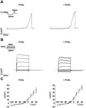
Thus, to analyze the impact of PANi on the bioelectrical properties of astrocytes, we next performed whole-cell patch-clamp measurements on single cells 24–48 h after re-plating on aligned −PANi and +PANi samples (Fig. 6).20,26
The passive membrane properties were calculated (ESI Table S1†) and revealed that the values of the voltage membrane (Vmem), input resistance (IR) and specific conductance (SpG) of the astrocytes on aligned −PANi and +PANi are very similar to those reported for primary astrocytes grown in vitro on PDL and simple PCL-based samples, while the membrane capacitance (Cp) of astrocytes seeded on +PANi substrates is significantly lower than that of those seeded on −PANi.20,48 The capacitance of cells is a measure of the cell surface area.39–41 Thus, the lower value of the cell capacitance of the cells grown on +PANi substrates confirms the morphological changes observed with the microscopical analyses.
The ramp-current traces for the astrocytes on both aligned −PANi and +PANi (Fig. 6A) as well as the voltage step family-evoked current analyses (Fig. 6B) indicated that astrocytes plated on −PANi and +PANi displayed voltage-gated delayed rectifier K+ channels, previously observed in non-differentiated astrocytes in vitro and essential for astrocyte physiology in vivo (Fig. 6). The graph in panel 6C shows the I–V plots built with the mean values of the maximal current values of astrocytes plated on aligned −PANi and +PANi. I–V plots were generated by calculating the averages of the maximal current values recorded at the peak (black circles) and steady state (white circles) and normalized for the relative cell capacitance values in cells grown on −PANi and +PANi substrates. The plot quantitatively represents the voltage and time dependency of the recorded currents. The data suggested that voltage and time-dependency of the whole-cell currents of astrocytes are not altered by the presence of PANi nanoneedles embedded in the PCL scaffold. Thus, the presence of PANi nanoneedles does not alter the biophysical properties of the whole cell currents of the astrocytes. Moreover, the analyses revealed that the magnitude and the biophysical profile of those currents was comparable to those previously described for astrocytes grown on PCL electrospun nanofibres, supporting the tenet that inclusion of PnNs in the fibres preserves the function of astrocytes in vitro.
It is known that the presence of a conductive substrate may rearrange the electric fields that can be locally generated by living cells, which in turn may affect cell morphology and behavior, even without the need for the application of an extracellular field.42 The local electric fields generated by the cells correlate with the bioelectrical activity of the cells and, in turn, with the function or the expression of ion channels on the cell plasma-membrane. The resting bioelectrical properties as well as the voltage- and time-dependency of the currents recorded in the astrocytes are unchanged in the presence of PnNs. Given that the functional properties of the astrocytes observed in the presence or absence of PnNs are comparable, we cannot rule out that in line with other work on different substrates, the expression pattern of the protein channels can be altered by the presence of PANi and that this effect may be accompanied by or account for changes observed in the cell morphology.20,26 Further investigations are needed with respect to this issue.
Previous studies reported different cell behaviours elicited in response to electrical stimulation, influencing directional cell movement, cell migration rate, cell alignment, cell division rate and orientation, and cell morphology.24,38–41 With regard to astrocytes, recent studies indicated that is possible to modulate the structural and functional properties of astrocytes by acute and chronic application of extracellular electric fields.38–41 Alexander et al. showed that orientation of astrocytes can be achieved by continuous extracellular electrical stimulation.44 Nonetheless, astrocyte orientation promotes neurite outgrowth of neurons of the same co-culture.15,44 The possibility to induce astrocyte migration by application of an extracellular electric field has also been demonstrated.43 In addition, our group has recently demonstrated that an extracellular electric field applied by means of an organic cell stimulating and sensing transistor44–47 evoked specific calcium signalling in astrocytes in vitro,36 which is important for their cross-talk with neurons in vivo. All these data indicate that electrical stimulation of astrocytes is a potential therapeutic target (i) to drive astroglial cell migration at the lesion sites during inflammatory gliotic reaction, (ii) to promote the alignment of astrocytic processes that may support and direct neurite outgrowth of the injured area, or (iii) to acutely modulate their functional properties, which is essential for proper neuronal cell synaptic activity.
4. Conclusions
In the present work, we have investigated the effects of PnNs embedded into bioactive electrospun fibres on the viability as well as on the structural and functional properties of primary astrocytes. The integration of PnNs in the scaffold (i) allows adhesion and growth of astrocytes over time; (ii) supports actin cytoskeleton rearrangement and a focal adhesion complex by promoting a higher degree of cell alignment (iii) without relevant effects on the active/passive bioelectrical properties of the astrocytes.It is well known that conductivity is a key material property for successfully recovering nerve injury and nerve outgrowth.45,46 Our data confirm that the presence of PnNs in addition to peculiar topographic and chemical cues of the electrospun substrates may provide a functional interface that is permissive of the adhesion, growth and function of astrocytes. Given the clear evidence from other authors that driving the properties of astrocytes may further reinforce the outgrowth of neurons promoted by the nanostructured scaffold,18,21,47 the electrospun fibre embedded with PnNs herein reported could represent a novel glial interface18,49 that can be potentially used to stimulate and possibly record astrocytes, aiming at the recovery of neuronal structure and function.
Conflicts of interest
There are no conflicts to declare.Acknowledgements
This work has been financially supported by AFOSR (ASTROMAT FA9550 16-1-0502, ASTRONIR FA9550-17-1-0502 3D NEUROGLIA FA9550-18-1-0255, ASTRODYN FA9550-19-1-0370) and Por Fesr Emilia Romagna 2014-2020 (MAT2REP PG/2018/626605).Notes and references
- N. Yamamoto and G. Lopez-Bendito, Eur. J. Neurosci., 2012, 35, 1595–1604 CrossRef PubMed
.
- Q. Wang and W. Teng, Int. J. Nanomed., 2016, 11, 131–145 CrossRef PubMed
.
- C. E. Schmidt, V. R. Shastri, J. P. Vacanti and R. Langer, Proc. Natl. Acad. Sci. U. S. A., 1997, 19, 8948–8953 CrossRef PubMed
.
- Q. Zhang, D. Esrafilzadeh, J. M. Crook, R. Kapsa, E. M. Stewart, E. Tomaskovic-Crook, G. G. Wallace and X. F. Huang, Sci. Rep., 2017, 7, 42525, DOI:10.1038/srep42525
.
- R. Balint, N. J. Cassidy and S. H. Cartmell, Acta Biomater., 2014, 10, 2341–2353 CrossRef PubMed
.
- K. Feron, R. Lim and P. C. Dastoor, Int. J. Mol. Sci., 2018, 8, 2382 CrossRef PubMed
.
- B. Li, V. Agarwal, D. Ho, J. P. Vede and K. L. Swaminathan, New J. Chem., 2018, 42, 7237–7240 RSC
.
- V. Guarino, S. Zuppolini, A. Borriello and L. Ambrosio, Polymers, 2016, 8, 185 CrossRef PubMed
.
- L. Yu-Sang, C. Bei-Fan, L. Xiao-Jun, K. Z. Wei and T. He-Bin, PLoS One, 2014, 9, e107361, DOI:10.1371/journal.pone.0107361
.
- S. Kamalesh, P. Tan, J. Wang, T. Lee, E. T. Kang and C. H. Wang, J. Biomed. Mater. Res., 2000, 52, 467–478 CrossRef PubMed
.
- R. Sarvari, B. Massoumi, M. Jayman, Y. Beygi-Khosrowshahic and M. Abdollahid, RSC Adv., 2016, 6, 19437–19451 RSC
.
- L. Huang, X. Zhuang, J. Hu, L. Lang, P. Zhang, Y. Wang, X. Chen, Y. Wei and X. Jing, Biomacromolecules, 2008, 9, 850–858 CrossRef PubMed
.
- P. R. Bidez, S. Li, A. G. Mac Diarmid, E. C. Venancio, Y. Wei and P. I. Lelkes, J. Biomater. Sci., Polym. Ed., 2006, 17, 199–212 CrossRef PubMed
.
- A. Borriello, V. Guarino, L. Schiavo, M. A. Alvarez-Perez and L. Ambrosio, J. Mater. Sci.: Mater. Med., 2011, 22, 1053–1062 CrossRef PubMed
.
- Q. Zhang, S. Beirne, K. Shu, D. Esrafilzadeh, X. F. Huang and G. G. Wallace, Sci. Rep., 2018, 8(1), 9855, DOI:10.1038/s41598-018-27784-5
.
- V. Benfenati and S. Ferroni, Neuroscience, 2010, 168(4), 926–940 CrossRef PubMed
.
- A. Verkhratsky and M. Nedergaard, Physiol. Rev., 2018, 98, 239–389 CrossRef PubMed
.
- L. Maiolo, V. Guarino, E. Saracino, M. Melucci, A. Convertino, L. Ambrosio, M. Muccini, R. Zamboni and V. Benfenati, Adv. Healthcare Mater., 2021, 10, 2001268 CrossRef PubMed
.
- J. W. Salatino, K. A. Ludwig, D. Y. Kozai and E. K. Purcell, Nat. Biomed. Eng., 2017, 1, 862–867 CrossRef PubMed
.
- S. Ferraris, S. Spriano, A. C. Scalia, A. Cochis, L. Rimondini, I. Cruz-Maya, V. Guarino, A. Varesano and C. Vineis, Topographical and Biomechanical Guidance of Electrospun Fibers for Biomedical Applications, Polymers, 2020, 12(12), 2896 CrossRef PubMed
.
- J. M. Zuidema, R. J. Gilbert and M. K. Gottipati, Cells Tissues Organs, 2018, 205, 372–395 CrossRef PubMed
.
- I. Cruz-Maya, A. Varesano, C. Vineis and V. Guarino, Comparative Study on Protein-Rich Electrospun Fibers for in Vitro Applications, Polymers, 2020, 12, 1671, DOI:10.3390/polym12081671
.
- E. Saracino, L. Maiolo, D. Polese, M. Semprini, A. I. Borrachero-Conejo, J. Gasparetto, M. Sola, L. Tomasi, F. Valle, L. Pazzini, F. Formaggio, M. Chiappalone, S. Hussain, M. Caprini, M. Muccini, L. Ambrosio, G. Fortunato, R. Zamboni, A. Convertino and V. Benfenati, Adv. Biosyst., 2020, 1900264, DOI:10.1002/adbi.201900264
.
- V. Benfenati and S. Ferroni, in Homeostatic control of brain function, ed. D. Boison and S. A. Masino, Oxford University Press, 1st edn, 2015, 1, pp. 3–40 Search PubMed
.
- V. Benfenati, S. Toffanin, R. Capelli, L. M. Camassa, S. Ferroni, D. L. Kaplan, F. G. Omenetto, M. Muccini and R. Zamboni, Biomaterials, 2010, 31, 7883–7891 CrossRef PubMed
.
- V. Benfenati, N. Martino, M. R. Antognazza, A. Pistone, S. Toffanin, S. Ferroni, G. Lanzani and M. Muccini, Adv. Healthcare Mater., 2014, 3, 392–439 CrossRef PubMed
.
- E. Saracino, V. Cirillo, M. Marrese, V. Guarino, V. Benfenati and R. Zamboni, Mater. Sci. Eng., C, 2021, 118, 111363 CrossRef PubMed
.
- T. Posati, A. Pistone, E. Saracino, F. Formaggio, M. G. Mola, E. Troni, A. Sagnella, M. Nocchetti, M. Barbalinardo, F. Valle, S. Bonetti, M. Caprini, G. P. Nicchia, R. Zamboni, M. Muccini and V. Benfenati, Sci. Rep., 2016, 6, 1–16 CrossRef PubMed
.
- Y. Li, B. Chen, X. Li, W. K. Zhang and H. Tang, PLoS One, 2014, 9, 107361, DOI:10.1371/journal.pone.0107361
.
- M. Marrese, V. Guarino, I. Fasolino, V. Cirillo and L. Ambrosio, Int. J. Polym. Mater., 2017, 67, 961–966 CrossRef
.
- V. Cirillo, B. A. Clements, V. Guarino, J. Kohn and L. Ambrosio, Biomaterials, 2014, 35, 8970–8982 CrossRef PubMed
.
- M. A. Alvarez Perez, V. Guarino, V. Cirillo and L. Ambrosio, J. Biomed. Mater. Res., Part A, 2012, 100(11), 3008–3019 CrossRef PubMed
.
- V. Guarino, V. Cirillo, R. Altobelli and L. Ambrosio, Expert Rev. Med. Devices, 2015, 12, 113–129 CrossRef PubMed
.
- V. Cirillo, V. Guarino, M. A. Alvarez-Perez, M. Marrese and L. Ambrosio, J. Mater. Sci.: Mater. Med., 2014, 25, 2323–2332 CrossRef PubMed
.
- V. Benfenati, M. Caprini, M. Nobile, C. Rapisarda and S. Ferroni, J. Neurochem., 2006, 98, 430–445 CrossRef
.
- A. Borrachero-Conejo, E. Saracino, M. Natali, F. Prescimone, S. Karges and S. Bonetti, Adv. Healthcare Mater., 2019, 8, 1801139, DOI:10.1002/adhm.201801139
.
- M. Bramini, S. Sacchetti, A. Armirotti, A. Rocchi, E. Vázquez, V. L. Castellanos, T. Bandiera, F. Cesca and F. Benfenati, ACS Nano, 2016, 10, 7154–7171 CrossRef PubMed
.
- M. Bramini, M. Chiacchiaretta, A. Armirotti, A. Rocchi, A. Kale, D. Deepali, M. C. E. Vázquez, T. Bandiera, S. Ferroni, F. Cesca and F. Benfenati, Small, 2019, 15, 1900147 CrossRef PubMed
.
- C. S. Hansel, S. W. Crowder, S. Cooper, S. Gopal, M. João Pardelha da Cruz, L. de Oliveira, D. M. Keller, S. Rothery, M. Becce, A. E. G. Cass, C. Bakal, C. Chiappini and M. M. Stevens, ACS Nano, 2019, 13, 2913–2926 CrossRef PubMed
.
- S. Sundelacruz, M. Levin and D. L. Kaplan, Stem Cell Rev. Rep., 2009, 5, 231–246 CrossRef PubMed
.
- T. A. Banks, P. S. B. Luckman, J. E. Frith and J. J. Cooper-White, Integr. Biol., 2015, 7, 693–712 CrossRef PubMed
.
- C. Chen, X. Bai, Y. Ding and Y. I. S. Lee, Biomater. Res., 2019, 23, 25 CrossRef PubMed
.
- H. W. Funk Richard, Front. Physiol., 2015, 6, 143 Search PubMed
.
- J. K. Alexander, B. Fuss and R. J. Colello, Neuron Glia Biol., 2006, 2, 93–103 CrossRef PubMed
.
- B. R. Borgens, R. Shi, T. J. Mohr and B. J. Christine, Exp. Neurol., 1994, 128, 41–49 CrossRef PubMed
.
- C. Yang, W. Lei, W. Weiji, S. Wang, M. Yuxiao, Q. Mao, G. Gao, R. Chen and J. Feng, Exp. Cell Res., 2019, 374, 282–289 CrossRef PubMed
.
- V. Benfenati, S. Toffanin, S. Bonetti, G. Turatti, A. Pistone, M. Chiappalone, A. Sagnella, A. Stefani, G. Generali, G. Ruani, D. Saguatti, R. Zamboni and M. Muccini, Nat. Mater., 2013, 7, 672–680 CrossRef PubMed
.
- T. W. Hsiao, P. A. Tresco and V. Hlady, Biomaterials, 2015, 39, 124–130 CrossRef PubMed
.
- R. Fabbri, E. Saracino, E. Treossi, R. Zamboni, Palermo and V. Benfenati, Nanoscale, 2021 10.1039/D0NR07824G
.
Footnote |
| † Electronic supplementary information (ESI) available. See DOI: 10.1039/d1ra00596k |
| This journal is © The Royal Society of Chemistry 2021 |

