 Open Access Article
Creative Commons Attribution 3.0 Unported Licence
Co2GeO4 nanocomposites with reduced graphene oxide and carbon nanotubes as high-performance anodes for Na-ion batteries
Bushra Nawaza,
Ghulam Ali *b,
Muhammad Obaid Ullaha,
Fauzia Iqbalc,
Faiza Jan Iftikhar
 d,
Sheeraz Mehboob
 e,
Ata-Ur Rehmanf and
Syed Mustansar Abbas
 g
g
aDepartment of Electronics Engineering, University of Engineering and Technology Taxila, Taxila, 47080, Pakistan
bUSPCAS-E, National University of Sciences and Technology (NUST), Sector H-12, Islamabad, 44000, Pakistan. E-mail: ali@uspcase.nust.edu.pk
cDepartment of Physics, University of the Punjab, Lahore, 54590, Pakistan
dNUTECH School of Applied Sciences and Humanities, National University of Technology, Islamabad, Pakistan
eChemistry Division, Directorate of Science, PINSTECH, Nilore, Islamabad, Pakistan
fChemistry Department, Govt. Postgraduate College, Asghar Mall, Rawalpindi, Pakistan
gNanoscience and Technology Department, National Centre for Physics, Islamabad, Pakistan
First published on 6th April 2021
Abstract
Heterostructure nanomaterials have attracted attention as potential anodes for sodium-ion batteries (NIBs), owing to their outstanding properties. In this work, a single-step facile hydrothermal route was adopted for the synthesis of Co2GeO4, Co2GeO4/rGO, and Co2GeO4/MWCNT nanocomposites. The X-ray diffraction analysis reveals the spinel phase formation of Co2GeO4, Co2GeO4/rGO, and Co2GeO4/MWCNTs. Scanning and transmission electron microscopy results depict the growth of pristine Co2GeO4 and Co2GeO4/rGO nanocomposites in the nanoscale size with sharp-edge plate-like morphology, while plate-like particles in Co2GeO4/MWCNT nanocomposites are grown on the surface and inside MWCNTs. The chemical bonding, oxidation state of elements in the composition, and the presence of rGO and MWCNTs are confirmed by X-ray photoelectron spectroscopy. The galvanostatic measurements reveal that Co2GeO4, Co2GeO4/rGO, and Co2GeO4/MWCNT electrodes exhibit specific capacities of 314, 425 and 475 mA h g−1 respectively at a rate of 0.05C. The rate capability and long cycle testing results show higher specific capacity and structural stability of Co2GeO4/MWCNT nanocomposites. Co2GeO4/MWCNT nanocomposites show a specific capacity of 108 mA h g−1 at a high current density of 6.4C. Sodium diffusion coefficient was calculated using a galvanostatic intermittent titration technique and values were calculated in the range of 10−14 to 10−16 cm2 s−1 and 10−13 to 10−16 cm2 s−1 for Co2GeO4/rGO, and Co2GeO4/MWCNTs, respectively, which are greater than the values of pristine Co2GeO4 (10−15 to 10−17 cm2 s−1). This indicates the improved sodium-ion diffusion kinetics of Co2GeO4/rGO and Co2GeO4/MWCNT nanocomposites, indicating their superior electrochemical performance to pristine Co2GeO4.
1. Introduction
There is a huge demand for rechargeable batteries owing to the vast and ever-growing market of energy storage systems. To quell this need, sodium-ion batteries (NIBs) are being deliberated as a likely substitute to lithium-ion batteries (LIBs). NIBs have captured much consideration because Na is the fourth most abundant element in the earth crust, cheap and environmentally friendly, unlike its rival Li. Moreover, Na has the ability to utilize electrolytes that have low decomposition potential.1–4 However, the low energy densities of NIBs mar their performance parameters, which limits the economic friendliness of sodium. There are three ways to improve the energy density. First, using materials, which possess high specific capacities as electrodes. Second, cathode materials with high working potentials can increase the energy density. Third, to improve the energy density, anode materials should have low redox potentials. Nevertheless, increasing the specific capacity of the cathode materials is difficult due to the limitation in storage sites. Electrolyte decomposition at high potentials also limits the utilization of cathode materials having high redox potentials. Therefore, in a bid to increase the energy density of NIBs, the development of anode materials with intrinsic high specific capacities and low working potentials is the best approach.5–9Alloy-type anode materials from group 14 elements have high theoretical capacities, so they have been thoroughly studied in LIBs. Hence, those elements can also be used to improve the capacity of NIBs because sodium behaves similar to lithium.10,11 Among group 14 elements, Si is considered a poor choice to be used as an anode material due to their low activity in NIBs.5,12 However, Si is being reported with oxycarbide where it delivered a limited capacity of 233 mA h g−1.13 By contrast, Sn delivers high capacity; however, the volume expansion despite high capacity limits their utilization. This volume change occurs as the sodiation of Sn leads to a gradual pulverization of the electrode material and can cause poor cycling stability during the electrochemical process.14–16 However, Ge is a prospective anode material for NIBs as Ge has better reversible capacities and capacity retention than Si or Sn anodes.17–20 Furthermore, the use of Ge with other 3D metal oxides provides higher capacity values and better reversibility.
Despite the high theoretical capacity of Ge, the electrochemical performance is considerably affected by its intrinsic shortcomings such as low cycling stability, capacity fading, and volume expansion (become more worst in NIBs because of the larger ionic radius of Na). Moreover, Ge owing to its poor electrical conductivity and volume expansion during sodium insertion/extraction has meagre cycling performance.21 Thus, to overcome these shortcomings, there is a need to develop the hybrid architecture for NIB anodes.
To lessen the volume change of alloy anode materials, there are many strategies such as reducing the size to the nanoscale, coating of carbonaceous materials, architecting a void space to bear the volume change, and lastly forming 2D or 3D heterostructures with other elements to buffer the volume expansion during the sodiation/desodiation process.22,23 The exhaustively employed way is to reduce the size of Ge to the nanoscale, thereby reducing the pathways for sodium ion diffusion. However, this also greatly affects the electronic conductivity because of the induced quantum confinement effect at the nanoscale.24 The coating of carbonaceous materials on the surface of anode materials has also been proved as an effective strategy for increasing the cyclic stability.25 This layering of carbon can accommodate the internal stress caused by severe volume change during sodium ion insertion and extraction with high electrochemical activity, thus improve the cycling stability. Lastly, but most importantly, the formation of binary or ternary composite with carbonaceous materials like graphene and carbon nanotubes (CNTs) can also mitigate structural degradation due to the volume expansion.
Graphene among carbon materials has been proven a perfect structure due to its excellent chemical stability and marvelous electrical conductivity. Moreover, graphene with its superior mechanical stability and high specific surface area also acts as a cushion layer to accommodate the electrode materials after their enormous volume expansion, and thus, it can avoid structure destruction. Similarly, like graphene, multi-walled carbon nanotubes (MWCNTs) also provide high electronic conductivity, accommodate the volume expansion, reduce ion diffusion pathways, and increase stability with efficient contact with anode materials. The materials can be grown both inside and on the surface of MWCNTs.26
Nanorods of Cu3Ge coated by nitrogen-doped carbon were prepared by Le Hu et al. as the anode of NIBs, which delivered a capacity of 160 mA h g−1 at a current rate of 100 mA g−1 for 500 cycles.27 Qin et al. synthesized GeO2/reduced graphene oxide (rGO) composites, which demonstrated excellent sodium storage properties even at 1 A g−1 and also showed good cycling stability.28 Qun Li et al. prepared a hybrid anode for NIBs and LIBs, where Ge nanoparticles were encapsulated in hollow carbon boxes that delivered a capacity close to the theoretical capacity of germanium.29 The hollow carbon structure not only enhanced electronic conductivity but also prevented the volume expansion of Ge at high rates with cyclic stability. In a recent work, the Co2GeO4/graphene-based anode is explored for NIBs, while providing a dynamic structure for ion storage. This anode has shown outstanding performance in terms of metrics such as capacity (319 mA h g−1), rate capability (151 mA h g−1 at 1 A g−1) and cycling stability (84%).30 Rahman et al. have prepared a Co3O4/CNT composite as an anode for NIBs. The Co3O4 anchored on the CNT has shown a better capacity and coulombic efficiency than those of the pristine Co3O4 electrode.31 Metal oxides suffer from poor cycling performance due to the particle division, aggregation and collapsing of the structure as anodes in batteries. The use of carbonaceous materials is the best way to lessen the aggregations of particles during charging and discharging with improvement in structural stability and capacity retention. Moreover, making heterostructures of graphene and CNT can improve the rate capability by faster electronic flow to the redox site due to electronegativity difference, thus eventually improving energy parameters.32,33
A high-performance NIB needs electrode materials with a flexible and smart architecture. In recent years, heterostructure architectures like 2D and 3D have attracted great attention for their prospective applications in energy devices because of their large surface areas and nanosized thickness. For high power density devices, 2D and 3D structures could also provide abundant reaction activity sites, shorter and faster transmission paths for electrons and ions and can prevent the aggregation of nanograins during the electrochemical process.34
In this work, the synthesis and thorough electrochemical performance of bare Co2GeO4, Co2GeO4/rGO and Co2GeO4/MWCNT nanocomposites are explored in NIBs. The prepared materials have uniform size and high yield, and contain numerous nanochannels to provide facile diffusion of sodium ions. The structural, morphological, chemical bonding, and electrochemical features of Co2GeO4, Co2GeO4/rGO and Co2GeO4/MWCNTs are examined by X-ray diffraction (XRD), scanning electron microscopy (SEM), high-resolution transmission electron microscopy (HR-TEM), and X-ray photoelectron spectroscopy (XPS) to comprehend the electrochemical process and storage mechanism. The synergetic effects between Co2GeO4 and rGO/MWCNTs have improved cyclic stability and rate capabilities. Therefore, such materials are expected to be favorable candidates for use as anodes in NIBs.
2. Experimental
2.1. Materials
Sodium hydroxide (≥98%), germanium oxide (99.99%), and cobalt chloride hexahydrate (98%) were purchased from Sigma-Aldrich. Multi-walled carbon nanotubes (>90% MWCNTs basis) were purchased from Sigma-Aldrich with a length of 5–9 μm and a diameter of 110–170 nm.2.2. Synthesis
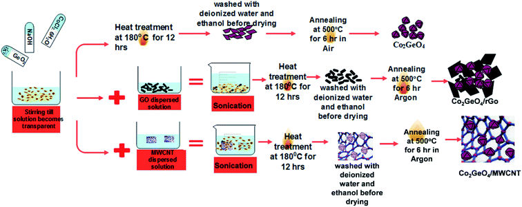
Co2GeO4, and its composites Co2GeO4/rGO and Co2GeO4/MWCNTs were synthesized by a hydrothermal method. The nanoparticles of Co2GeO4 were synthesized via the hydrothermal route, which is elaborated in Scheme 1.2.3. Preparation of Co2GeO4
First, an alkali solution was prepared in 30 ml of deionized water by adding 0.5 mmol of NaOH. After this, 0.5 mmol of GeO2 was dissolved in the above solution under magnetic stirring until a clear solution was formed. Later, 1 mmol of CoCl2·6H2O was put into this solution and continuously stirred for another 10 min. Then, the precursor suspension containing dissolved reagents was poured into a Teflon-lined autoclave having a capacity of 200 ml. The autoclave was upheld at a temperature of 180 °C for 12 h. Afterwards, it was permitted to cool down naturally to room temperature. These precipitates were centrifuged, washed several times with deionized water and absolute ethanol to remove the byproducts, and dried overnight at approximately 80 °C. In the end, the final product was obtained by annealing of this powder in air atmosphere at ∼500 °C for 6 h and labeled as Co2GeO4. The yield of the Co2GeO4 powder was measured as ∼250 mg after calcination. Graphene oxide and CNTs were added 5 wt% of the yield of Co2GeO4 powder.2.4. Preparation of Co2GeO4/rGO composites
Graphene oxide was obtained from natural graphite powder by modified Hummer's method. In the conventional synthesis process, graphene oxide was added into a deionized water solution and sonicated for about 1 h. To 30 ml of deionized water, 0.5 mmol of NaOH, 0.5 mmol of GeO2, and 1 mmol of CoCl·6H2O were added. Later, the graphene oxide solution was added into the above suspension and sonicated for 30 minutes. The combined reagent solution was upheld at a temperature of 180 °C for 12 h under the hydrothermal treatment. It is worthy to mention here that graphene oxide was reduced by NaOH in the solution. At the end of the reaction, the acquired composite was washed several times with deionized water and absolute ethanol and later dried out overnight at 80 °C. Afterwards, the sample was calcined at a temperature of 500 °C for 6 h at a ramping rate of 1 °C per minute in Ar atmosphere to guarantee good adherence between rGO and Co2GeO4 composites.2.5. Preparation of Co2GeO4/MWCNT composites
Co2GeO4/MWCNT composites were synthesized by the same facile hydrothermal method, as described above. MWCNTs were added to 20 ml of distilled water and sonicated for 2 h to form its uniformly dispersed solution. Then, to a 30 ml solution containing cobalt, germanium precursor, this MWCNT solution was added. The solution was treated hydrothermally and preserved at a temperature of 180 °C for 12 h. Subsequently, the obtained precipitates were washed several times with deionized water and absolute ethanol, in an effort to get rid of the impurities. Lastly, the synthesized sample was annealed at a temperature of 500 °C for 6 h in argon gas environment, with a slow ramping rate of 1 °C per minute for good adherence between Co2GeO4 and MWCNT composites.2.6. Characterization
X-ray diffraction examination was performed to determine the phase purity of the composites using a Bruker APEX-II diffractometer equipped with a Mo Kα source. Surface and morphological properties were examined by SEM (NOVA FE-SEM, FEI). The microstructure analysis of Co2GeO4, Co2GeO4/rGO and Co2GeO4/MWCNT composites was performed using a TEM (G2 F20 FEI, Tecnai). XPS (Thermo Scientific, XPS) equipped with an Al-Kα X-ray source was used to identify the functional groups and elements in the composite. The CR 2032 cell assembly was used to assess the electrochemical properties of the prepared materials. The working electrodes were prepared by mixing produced nanocomposites as the active material, Super P carbon, and polyvinylidene difluoride as the binder in a weight ratio of 7![[thin space (1/6-em)]](https://www.rsc.org/images/entities/char_2009.gif) :
:![[thin space (1/6-em)]](https://www.rsc.org/images/entities/char_2009.gif) 2
2![[thin space (1/6-em)]](https://www.rsc.org/images/entities/char_2009.gif) :
:![[thin space (1/6-em)]](https://www.rsc.org/images/entities/char_2009.gif) 1. This mixture was dissolved in a N-methyl-2-pyrrolidinone solvent to create a paste. The prepared paste was spread on the copper file. Afterwards, the casted Cu foil was dried in a vacuum oven to remove the byproducts of N-methyl-2-pyrrolidinone. The average mass loading of the active materials was in the range of 2.2–2.6 mg. The electrochemical cells were assembled in an argon-filled glove box in a controlled environment with optimized values (<0.1 ppm) of oxygen and moisture. The electrolyte was made up of 1 M NaClO4 dissolved in diethyl carbonate, propylene carbonate, and ethylene carbonate with an identical weight ratio. Later, 3 wt% fluoroethylene carbonate was added to the above electrolyte solution. The selection and amount of the electrolyte play an important role in electrochemical performance.35,36 The amount of 1 M NaClO4 in the range of 50–100 μl was used to make coin cells. The composite electrochemical properties were tested using a Gamry Instrument.
1. This mixture was dissolved in a N-methyl-2-pyrrolidinone solvent to create a paste. The prepared paste was spread on the copper file. Afterwards, the casted Cu foil was dried in a vacuum oven to remove the byproducts of N-methyl-2-pyrrolidinone. The average mass loading of the active materials was in the range of 2.2–2.6 mg. The electrochemical cells were assembled in an argon-filled glove box in a controlled environment with optimized values (<0.1 ppm) of oxygen and moisture. The electrolyte was made up of 1 M NaClO4 dissolved in diethyl carbonate, propylene carbonate, and ethylene carbonate with an identical weight ratio. Later, 3 wt% fluoroethylene carbonate was added to the above electrolyte solution. The selection and amount of the electrolyte play an important role in electrochemical performance.35,36 The amount of 1 M NaClO4 in the range of 50–100 μl was used to make coin cells. The composite electrochemical properties were tested using a Gamry Instrument.
3. Results and discussion
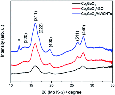
XRD analysis demonstrates the formation of the crystalline structure for Co2GeO4 and its rGO and MWCNT composites, as shown in Fig. 1. The peaks match well with the standard diffraction pattern (JCPDS no. 10-0464) for phase pure cubic Co2GeO4 with a lattice parameter of 0.8319 nm and Fd![[3 with combining macron]](https://www.rsc.org/images/entities/char_0033_0304.gif) m space group.37–39 The diffraction peaks are synched with the standard XRD data, which confirm the phase pure cubic structured Co2GeO4. It is worth mentioning that no extra peaks for phases like Co3O4 and GeO2 were observed. In the XRD diffraction pattern of Co2GeO4/MWCNTs, the extra peak at 12.06° could be assigned to the reflection plane (002) of the MWCNTs. The XRD patterns of composites show relatively high intensity peaks, which indicates a better crystalline structure due to the presence of rGO and MWCNTs. The Scherrer formula (eqn (1)) was utilized for the assessment of the crystallite size on a nanometer scale of the manufactured particles:
m space group.37–39 The diffraction peaks are synched with the standard XRD data, which confirm the phase pure cubic structured Co2GeO4. It is worth mentioning that no extra peaks for phases like Co3O4 and GeO2 were observed. In the XRD diffraction pattern of Co2GeO4/MWCNTs, the extra peak at 12.06° could be assigned to the reflection plane (002) of the MWCNTs. The XRD patterns of composites show relatively high intensity peaks, which indicates a better crystalline structure due to the presence of rGO and MWCNTs. The Scherrer formula (eqn (1)) was utilized for the assessment of the crystallite size on a nanometer scale of the manufactured particles:
 | (1) |
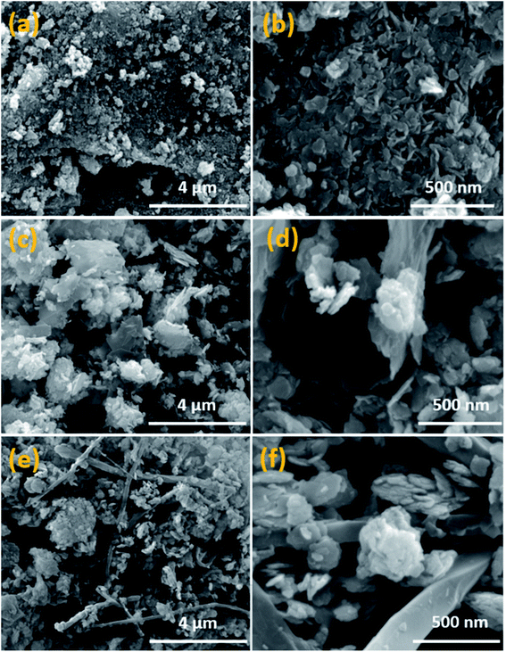
Field emission SEM is employed to examine the surface morphology of Co2GeO4, Co2GeO4/rGO, and Co2GeO4/MWCNTs materials. In Fig. 2a and b, pristine Co2GeO4 exhibits flake-like nanoplates with the size ranging from 20 to 100 nm. All particles are in the nanoscale with slight aggregation of particles. In Fig. 2c and d, the Co2GeO4/rGO composite is seen uniformly distributed on graphene layers, which will result in fast charge transfer. Fig. 2e and f show the morphology of the Co2GeO4/MWCNT composite, where the particles are seen well consistently anchored on the MWCNTs. It is evident from the SEM images that MWCNTs have increased the uniformity of particle distribution.
TEM was performed to gain further understanding of the surface properties. Fig. 3a displays the existence of Co2GeO4 nanoplates with a sharp edge disk-like structure, and the high-resolution image (Fig. 3b) shows that the disks are further composed of tiny nanoparticles with a size <10 nm. Fig. 3c shows the selected area electron diffraction (SAED) image of pristine Co2GeO4 nanoplates, where the dotted circles show a crystalline structure with hkl values matched with the XRD pattern shown in Fig. 1. Fig. 3d and e display the morphology of Co2GeO4/rGO composites where the Co2GeO4 nanoparticles are entirely enfolded in the rGO layers. Hence, rGO layers will not only serve to boost up the electronic properties of the composite but also provide more reaction sites for composites. Agglomeration between the tiny Co2GeO4 nanoparticles was also observed in the Co2GeO4/rGO composite. Fig. 3f shows the SAED pattern of the Co2GeO4/rGO composite material with a crystalline structure. The Co2GeO4/MWCNT composite also shows agglomeration and the particles are attached on the surface of CNTs, as shown in Fig. 3g. High-resolution image (Fig. 3h) of the Co2GeO4/MWCNT composite shows that some tiny particles are also grown inside the CNTs. The microcrystallinity of the Co2GeO4/MWCNT composite was further confirmed with the SAED pattern, as shown in Fig. 3i. Compared with Co2GeO4, the size and shape of Co2GeO4/rGO and Co2GeO4/MWCNT composites were almost unchanged, which suggested that the introduction of rGO and MWCNTs does not affect the morphology of pristine Co2GeO4.
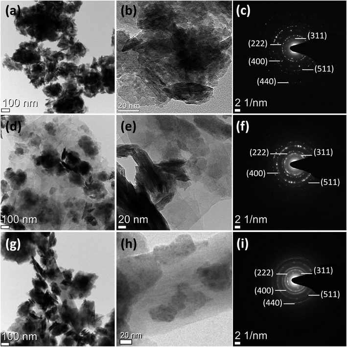 | ||
| Fig. 3 TEM and selected area electron diffraction images of (a–c) Co2GeO4, (d–f) Co2GeO4/rGO, and (g–i) Co2GeO4/MWCNTs. | ||
Fig. 4a displays the XPS survey spectra of Co2GeO4, Co2GeO4/rGO, and Co2GeO4/MWCNT composites. The survey spectra of all three composites display the occurrence of functional groups of C 1s, O 1s, Co 2p, and Ge 2p for elements C, O, Co, and Ge, respectively. Fig. 4b–e shows the individual deconvoluted spectra of C 1s, O 1s, Co 2p, and Ge 2p peaks. Fig. 4g shows the C 1s deconvoluted XPS spectrum of the Co2GeO4/rGO nanocomposite. The C 1s spectrum can be deconvoluted into two peaks at 284.7 and 286.1 eV, corresponding to the C–C bond and C–O bond, respectively. The high intensity of the C–C bond compared to the C–O bond indicates the presence of high carbon content, and less amount of oxygen appears due to the reduced graphene oxide. The C 1s XPS spectrum of the Co2GeO4/MWCNT nanocomposite shows two peaks at 284.7 and 286.1 eV, corresponding to C–C and C–O bonds, respectively. The presence of C–O bonds in the Co2GeO4/MWCNT nanocomposite could be attributed to the functionalized CNTs.40,41 Fig. 4c shows the O 1s peak at 531.9 eV for Co2GeO4, Co2GeO4/rGO, and Co2GeO4/MWCNTs, which is attributed to the metal oxide bond. The Co 2p deconvoluted spectra contain the two main peaks at 781.8 eV and 798.5 eV, which correspond to the Co 2p3/2 and Co 2p1/2 orbitals respectively, as shown in Fig. 4d, which are related with Co2+ ion binding energy in the Co2GeO4, Co2GeO4/rGO, and Co2GeO4/MWCNT compounds.37 The peaks at 787.5 eV and 804 eV were also observed, which are satellite peaks. Fig. 4e shows the spectra of Ge 2p, which has two main peaks at 1220 and 1252 eV, conforming to Ge 2p3/2 and Ge 2p1/2 orbits, respectively.37 These peaks show the Ge4+ oxidation state of Ge in all samples.
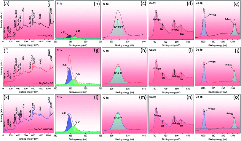 | ||
| Fig. 4 Survey and deconvoluted XPS spectra of C 1s, O 1s, Co 2p, and Ge 2p for Co2GeO4 (a–e), Co2GeO4/rGO (f–j), and Co2GeO4/MWCNTs (k–o). | ||
3.1Charge–discharge and cycle life performance
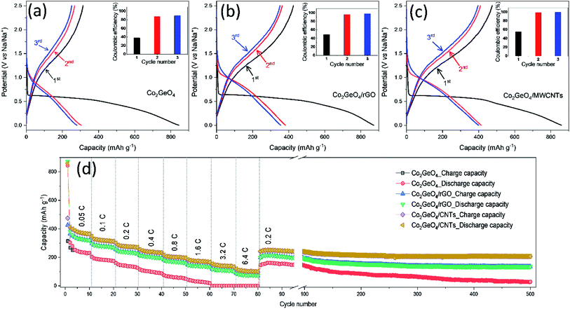
The galvanostatic performance of Co2GeO4, Co2GeO4/rGO, and Co2GeO4/MWCNT electrodes were investigated in a voltage window of 0.01–2.5 V. Fig. 5a shows the charge–discharge capacity of the pristine Co2GeO4 electrode for the first three cycles. In Fig. 5a, this first discharge curve shows a capacity of 844 mA h g−1 at a constant current rate of 0.05C with a large plateau, which is associated with the conversion of Co2GeO4 to metals and formation of Na2O. The first charge curve of the pristine Co2GeO4 electrode shows a capacity of 314 mA h g−1 with a coulombic efficiency of 37%. A low value of coulombic efficiency can be a result of electrolyte breakdown and the creation of the solid electrolyte interface (SEI) layer. This irreversible loss in capacity occurs due to the formation of the SEI film on the large contact interface between Co2GeO4 and the electrolyte. But this irreversible loss during the initial cycle is common in the anode materials with a large specific area. In later cycles, discharge/charge curves are well aligned with a high value of coulombic efficiency, signifying the high reversibility of the Co2GeO4 electrode. The pristine Co2GeO4 electrode shows charge capacities of 267 and 251 mA h g−1 during 2nd and 3rd cycles, respectively. When tested on high current densities, the pristine Co2GeO4 electrode exhibits average specific charge capacities of 244, 183, 142, 102, 60, and 31 mA h g−1 at rates of 0.05, 0.1, 0.2, 0.4, 0.8 and 1.6C, respectively, as shown in Fig. 5d. It is worthy to mention here that the pristine Co2GeO4 electrode shows negligible sodium storage at high rates of 3.2 and 6.4C. When the rate reset to 0.2C after deep current cycling, the pristine Co2GeO4 electrode recovers a specific capacity of 145 mA h g−1. The pristine Co2GeO4 electrode demonstrates reasonable retention from 80th to 100th cycle and then there was a capacity degradation till the 500th cycle, where the electrode shows a specific capacity of 29 mA h g−1, as shown in Fig. 5d.The Co2GeO4/rGO composite cell shows charge and discharge capacities of 425 and 871 mA h g−1 during the 1st cycle (Fig. 5b), with coulombic efficiency of 49%. This shows an improved value of coulombic efficiency compared to the pristine electrode. The capacity loss in the first cycle of all electrodes is mainly triggered by the creation of the SEI film after the electrolyte decomposition on the electrode surface. This passivation layer on the electrode results in the trapping of some sodium ions on the defect sites or nanoclusters. The 1st discharge curve is noticed different compared to the subsequent discharge curves. This is due to the different reaction mechanism during the 1st discharge process (eqn (2)) and subsequent discharge processes (eqn (4)), while the reaction mechanism during the charge process follows eqn (3):
| Co2GeO4 + 8Na → 2Co + Ge + 4Na2O | (2) |
| 2Co + Ge + 4Na2O → 2CoO + GeO2 + 8Na | (3) |
| 2CoO + GeO2 + 8Na → 2Co + Ge + 4Na2O | (4) |
The Co2GeO4/rGO composite cell delivers a charge and a discharge capacity of 364 and 382 mA h g−1 with a coulombic efficiency of 95% for the 2nd cycle, as shown in Fig. 5b. In the 3rd cycle, coulombic efficiency further increases to 99% with 352/355 mA h g−1 charge/discharge capacity. The Co2GeO4/rGO composite cell shows average specific capacities of 334, 278, 237, 204, 169, 141, 110, and 75 mA h g−1 at rates of 0.05, 0.1, 0.2, 0.4, 0.8, 1.6, 3.2, and 6.4C, respectively, as displayed in Fig. 5d. Interestingly, the Co2GeO4/rGO composite electrode shows a specific capacity of 87 mA h g−1 compared to a negligible capacity of the pristine electrode at a high current rate of 6.4C. This is due to rGO layers which not only increase the charge transfer but also enhance the reaction sites in the composite. The Co2GeO4/rGO composite electrode regains a specific capacity of 198 mA h g−1 during the 81st cycle when the rate reverted to 0.2C after deep cycling. The Co2GeO4/rGO composite electrode shows good capacity retention where the electrode shows the specific capacity of 136 mA h g−1 during the 500th cycle.
Fig. 5c shows the charged and discharge curves measured at 0.05C for Co2GeO4/MWCNT composite electrodes. The Co2GeO4/MWCNT composite electrode delivers a discharge/charge capacity of 859/474 mA h g−1 during the 1st cycle with a coulombic efficiency of 55%. This improved coulombic efficiency can be ascribed to better reversibility of sodium ions in rGO composite electrodes than the pristine electrode. The Co2GeO4/MWCNT composite electrode shows a discharge/charge capacity 413/409 mA h g−1 and 399/396 mA h g−1 for 2nd and 3rd cycles, respectively, while achieving a coulombic efficiency of 99%. The rate capability of Co2GeO4/MWCNTs was carried out under similar current densities as other electrodes with an interval of 10 cycles for each step. It is shown in Fig. 5d that the Co2GeO4/MWCNT electrode is capable of delivering the specific capacities of 378, 318, 277, 239, 201, 173, 140, and 103 mA h g−1 at different current rates of 0.05, 0.1, 0.2, 0.4, 0.8, 1.6, 3.2, and 6.4C, respectively. Remarkably, when the current density was reverted to 0.2C, the Co2GeO4/MWCNT electrode was capable of recovering the capacity of 241 mA h g−1. Thus, suggesting exceptional cycling stability and long cycle life of the electrode with enhanced electrochemical reversibility, even at the 500th cycle with a specific capacity of 207 mA h g−1. Hence, the Co2GeO4/MWCNT electrode has shown superior rate capability with good stability over 500 cycles, which is due to the fine attachment of CNTs with Co2GeO4 in the composite.
The synergistic effect of transition metal and MWCNTs results in enhanced electrochemical performance because MWCNTs can prevent the agglomeration of particles, buffer the volume changes along with a good conducting matrix, and provide better contact at the current collector. The CNTs when compared with graphene, despite its tough nature, high conductivity and stability, have advantages of faster electronic and ionic transmissions through the wall and interior tubular structure and less irreversible capacity loss. It has been reported Na-ion storage properties in the SnO2/MWCNT composite are better than those of bare and other carbon materials such as activated carbon, mesoporous carbon, and graphene nanosheets,42 while it has already been tested that CNTs have better electrochemical performance than rGO in terms of specific capacitance for supercapacitors and far better rate capability as anodes for SIBs and delivered 40 mA h g−1 for rGO and 100 mA h g−1 for CNTs.43,44
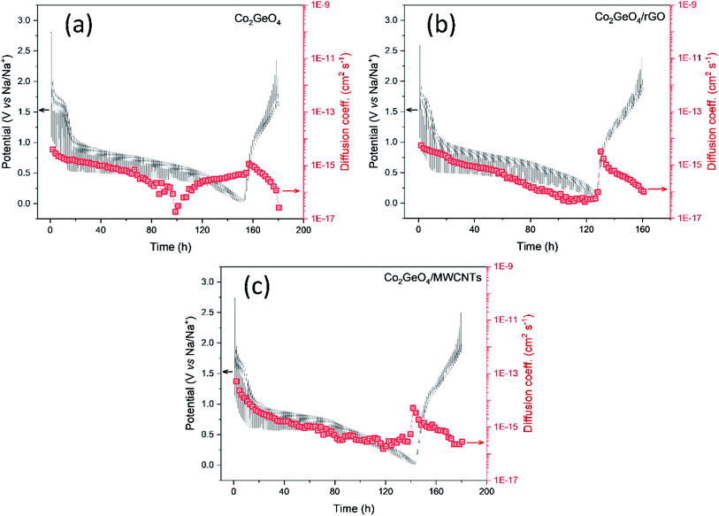
The diffusion kinetics of the sodium ions in the electrochemical process is examined by GITT, a technique based on chronopotentiometry established by Weppner and Huggins to measure the diffusion coefficient of mobile ions across the host structure. GITT employed both the steady-state and transient calculations; moreover, they also maintain the thermodynamic data. GITT experiments were performed on Co2GeO4, Co2GeO4/rGO, and Co2GeO4/MWCNTs anodes in a voltage window of 0.01–2.5 V at a current rate of 0.05C. The measured GITT profiles of all the electrodes as a function of potential along with the values of sodium ion diffusion coefficients (DNa+) are shown in Fig. 6a–c. The GITT data were collected by applying the current pulses for 10 minutes repeatedly followed by a resting time of 1 hour to get equilibrium during the whole charge/discharge process. It is assumed that Fick's second law is followed by sodium diffusion in the electrode, and the sodium ion diffusion coefficient (DNa) was measured using eqn (5):
 | (5) |
The calculated values of DNa for all electrodes displayed an irregularly decreasing fashion during the charge/discharge process and varied between 10−12 cm2 s−1 and 10−14 cm2 s−1. The values of DNa for the bare electrode are ∼10−15 cm2 s−1 at the starting of the discharge process and decrease to ∼10−17 cm2 s−1 at the completion of the discharge process. The DNa values in the Co2GeO4/rGO composite were calculated and found to vary in the range of ∼10−14 cm2 s−1 to ∼10−16 cm2 s−1 during start and completion of the discharge process. While the values of DNa for the Co2GeO4/MWCNT composite anode were calculated in the range of ∼10−13 cm2 s−1 to ∼10−16 cm2 s−1 during the 1st cycle. The sodium ions bear high polarization at the depth of charge and discharge, indicated by higher values of DNa at the beginning and lower values at the completion of the discharge process. This decline in values of sodium ion diffusion can be explained by the critically slowest electrochemical reactions in these regions because of the strong interference of other surrounding ions with diffusion kinetics of sodium ions. Due to the structural changes and change in potential from the open circuit to fully discharged state, sodium ion diffusion kinetics were compromised. The DNa values follow the same trend during the charge process as followed in the discharge process. Furthermore, the Co2GeO4/MWCNTs and Co2GeO4/rGO electrode exhibited slightly lower reaction resistances for both Na+ insertion and extraction processes than those of the pristine Co2GeO4 electrode, exhibiting the better sodium-ion diffusion kinetics and conforming well to the superior electrochemical performance of the rGO and MWCNT composites.
Hence, Co2GeO4/rGO and Co2GeO4/MWCNTs composites have displayed superior electrochemical performance, which can be attributed to their heterostructure. In these composites, the MWCNTs and rGO have offered multifold advantages than pristine Co2GeO4 such as reduction of the stress during the charge/discharge process, accommodation of the volume changes during the electrochemical reaction, providing better electronic conductivity, lessening the aggregation of the nanoparticles, and also reduction of the pathways for the sodium ion diffusion. All these factors result in better cycling stability and improved capacity of these composites, thus suggesting them as potential candidates for the NIBs.
4. Conclusion
Co2GeO4, Co2GeO4/rGO, and Co2GeO4/MWCNTs have been efficaciously synthesized by a single-step facile hydrothermal method. SEM analysis ensured that the morphology of all the prepared materials was in the nanoscale with a disc-like shape. HR-TEM images confirmed the wrapping of particles in rGO layers and homogenous dispersion of Co2GeO4 along the chains of MWCNTs in the composites. The Co2GeO4, Co2GeO4/rGO and Co2GeO4/MWCNT electrodes deliver charge/discharge capacities of 266/300, 362/380, and 408/411 mA h g−1 at 0.05C, respectively. Both composites deliver excellent long cycle testing for 500 cycles; however, the Co2GeO4/MWCNT electrode shows the highest capacity of 140 and 103 mA h g−1 at high current densities of 3.2C and 6.4C. The GITT technique showed that Co2GeO4/rGO and Co2GeO4/MWCNTs have higher values of sodium ion diffusion coefficient, which results in superior electrochemical performance to pristine Co2GeO4. Hence, Co2GeO4/rGO and Co2GeO4/MWCNTs have shown their tendency as potential anode materials for NIBs.Conflicts of interest
The authors declare no conflicts of interest.Acknowledgements
Ghulam Ali and Sheeraz Mehboob want to acknowledge KIST partnership project for financial help.References
- B. L. Ellis and L. F. Nazar, Curr. Opin. Solid State Mater. Sci., 2012, 16, 168–177 CrossRef CAS.
- C. Grosjean, P. H. Miranda, M. Perrin and P. Poggi, Renewable Sustainable Energy Rev., 2012, 16, 1735–1744 CrossRef.
- Y. Kim, K. H. Ha, S. M. Oh and K. T. Lee, Chem.–Eur. J., 2014, 20, 11980–11992 CrossRef CAS PubMed.
- D. S. Bhange, D. A. Anang, G. Ali, J.-H. Park, J.-Y. Kim, J.-H. Bae, W. Y. Yoon, K. Y. Chung and K.-W. Nam, Electrochem. Commun., 2020, 121, 106873 CrossRef CAS.
- S. Y. Hong, Y. Kim, Y. Park, A. Choi, N.-S. Choi and K. T. Lee, Energy Environ. Sci., 2013, 6, 2067–2081 RSC.
- S. W. Kim, D. H. Seo, X. Ma, G. Ceder and K. Kang, Adv. Energy Mater., 2012, 2, 710–721 CrossRef CAS.
- V. Palomares, M. Casas-Cabanas, E. Castillo-Martínez, M. H. Han and T. Rojo, Energy Environ. Sci., 2013, 6, 2312–2337 RSC.
- H. Pan, Y.-S. Hu and L. Chen, Energy Environ. Sci., 2013, 6, 2338–2360 RSC.
- G. Ali, A. Mehmood, M. Islam, M. Akbar, H.-S. Kim, H.-G. Jung, K.-W. Nam and K. Y. Chung, Ceram. Int., 2020, 46, 27711–27716 CrossRef CAS.
- S. C. Jung, H.-J. Kim, Y.-J. Kang and Y.-K. Han, J. Alloys Compd., 2016, 688, 158–163 CrossRef CAS.
- G. Ali, J.-H. Lee, S. H. Oh, H.-G. Jung and K. Y. Chung, Nano Energy, 2017, 42, 106–114 CrossRef CAS.
- M. Shimizu, H. Usui, K. Fujiwara, K. Yamane and H. Sakaguchi, J. Alloys Compd., 2015, 640, 440–443 CrossRef CAS.
- R. N. Putra, M. Halim, G. Ali, S. F. Shaikh, A. M. Al-Enizi, T. Fazal, F. Jan Iftikhar and A. N. S. Saqib, New J. Chem., 2020, 44, 14035–14040 RSC.
- M. K. Datta, R. Epur, P. Saha, K. Kadakia, S. K. Park and P. N. Kumta, J. Power Sources, 2013, 225, 316–322 CrossRef CAS.
- L. D. Ellis, T. D. Hatchard and M. N. Obrovac, J. Electrochem. Soc., 2012, 159, A1801 CrossRef CAS.
- S. Komaba, Y. Matsuura, T. Ishikawa, N. Yabuuchi, W. Murata and S. Kuze, Electrochem. Commun., 2012, 21, 65–68 CrossRef CAS.
- P. R. Abel, Y.-M. Lin, T. de Souza, C.-Y. Chou, A. Gupta, J. B. Goodenough, G. S. Hwang, A. Heller and C. B. Mullins, J. Phys. Chem. C, 2013, 117, 18885–18890 CrossRef CAS.
- J. K. Keum, J. F. Browning and G. M. Veith, Electrochem. Commun., 2013, 34, 41–44 CrossRef.
- A. Kohandehghan, K. Cui, M. Kupsta, J. Ding, E. Memarzadeh Lotfabad, W. P. Kalisvaart and D. Mitlin, Nano Lett., 2014, 14, 5873–5882 CrossRef CAS PubMed.
- X. Lu, E. R. Adkins, Y. He, L. Zhong, L. Luo, S. X. Mao, C.-M. Wang and B. A. Korgel, Chem. Mater., 2016, 28, 1236–1242 CrossRef CAS.
- W. Li, L. Ke, Y. Wei, S. Guo, L. Gan, H. Li, T. Zhai and H. Zhou, J. Mater. Chem. A, 2017, 5, 4413–4420 RSC.
- S. Liang, Y. J. Cheng, J. Zhu, Y. Xia and P. Müller-Buschbaum, Small Methods, 2020, 2000218 CrossRef CAS.
- J.-Y. Hwang, S.-T. Myung and Y.-K. Sun, Chem. Soc. Rev., 2017, 46, 3529–3614 RSC.
- Y. Son, M. Park, Y. Son, J.-S. Lee, J.-H. Jang, Y. Kim and J. Cho, Nano Lett., 2014, 14, 1005–1010 CrossRef CAS PubMed.
- D.-J. Xue, S. Xin, Y. Yan, K.-C. Jiang, Y.-X. Yin, Y.-G. Guo and L.-J. Wan, J. Am. Chem. Soc., 2012, 134, 2512–2515 CrossRef CAS PubMed.
- R. Ata Ur, G. Ali, A. Badshah, K. Y. Chung, K.-W. Nam, M. Jawad, M. Arshad and S. M. Abbas, Nanoscale, 2017, 9, 9859–9871 RSC.
- L. Hu, C. Shang, L. Huang, X. Wang and G. Zhou, Ionics, 2020, 26, 719–726 CrossRef CAS.
- W. Qin, T. Chen, B. Hu, Z. Sun and L. Pan, Electrochim. Acta, 2015, 173, 193–199 CrossRef CAS.
- Q. Li, Z. Zhang, S. Dong, C. Li, X. Ge, Z. Li, J. Ma and L. Yin, Part. Part. Syst. Charact., 2017, 34, 1600115 CrossRef.
- N. Kalaiselvi, J. Phys. Chem. Solids, 2020, 109863 Search PubMed.
- M. M. Rahman, I. Sultana, Z. Chen, M. Srikanth, L. H. Li, X. J. Dai and Y. Chen, Nanoscale, 2015, 7, 13088–13095 RSC.
- B. Wang, Y. Xie, T. Liu, H. Luo, B. Wang, C. Wang, L. Wang, D. Wang, S. Dou and Y. Zhou, Nano Energy, 2017, 42, 363–372 CrossRef CAS.
- B. Wang, T. Liu, A. Liu, G. Liu, L. Wang, T. Gao, D. Wang and X. S. Zhao, Adv. Energy Mater., 2016, 6, 1600426 CrossRef.
- S. Z. Butler, S. M. Hollen, L. Cao, Y. Cui, J. A. Gupta, H. R. Gutiérrez, T. F. Heinz, S. S. Hong, J. Huang and A. F. Ismach, ACS Nano, 2013, 7, 2898–2926 CrossRef CAS PubMed.
- H. Luo, B. Wang, F. Wang, J. Yang, F. Wu, Y. Ning, Y. Zhou, D. Wang, H. Liu and S. Dou, ACS Nano, 2020, 14, 7328–7337 CrossRef CAS PubMed.
- B. Wang, F. Jin, Y. Xie, H. Luo, F. Wang, T. Ruan, D. Wang, Y. Zhou and S. Dou, Energy Storage Mater., 2020, 26, 433–442 CrossRef.
- S. Jin, G. Yang, H. Song, H. Cui and C. Wang, ACS Appl. Mater. Interfaces, 2015, 7, 24932–24943 CrossRef CAS PubMed.
- D. Bauer, T. E. Ashton, A. R. Groves, A. Dey, S. Krishnamurthy, N. Matsumi and J. A. Darr, Energy Technol., 2020, 8, 1900692 CrossRef CAS.
- Y. Subramanian, K. Kaliyappan and K. S. Ramakrishnan, J. Colloid Interface Sci., 2017, 498, 76–84 CrossRef CAS PubMed.
- B. Wang, T. Ruan, Y. Chen, F. Jin, L. Peng, Y. Zhou, D. Wang and S. Dou, Energy Storage Mater., 2020, 24, 22–51 CrossRef.
- H. Luo, B. Wang, F. Wu, J. Jian, K. Yang, F. Jin, B. Cong, Y. Ning, Y. Zhou, D. Wang, H. Liu and S. Dou, Nano Energy, 2021, 81, 105601 CrossRef CAS.
- Y. Wang, D. Su, C. Wang and G. Wang, Electrochem. Commun., 2013, 29, 8–11 CrossRef CAS.
- Y. Bai, M. Du, J. Chang, J. Sun and L. Gao, J. Mater. Chem. A, 2014, 2, 3834–3840 RSC.
- J. Feng, L. Dong, X. Li, D. Li, P. Lu, F. Hou, J. Liang and S. X. Dou, Electrochim. Acta, 2019, 302, 65–70 CrossRef CAS.
| This journal is © The Royal Society of Chemistry 2021 |

