 Open Access Article
Creative Commons Attribution 3.0 Unported Licence
Temperature assistance of electric field-controlled spin–orbit torque-based magnetization switching in PMN–PT/FePt heterostructures†
Qi Guo and
Zhicheng Wang
 *
*
School of Materials Science and Engineering, Taiyuan University of Science and Technology, Taiyuan 030024, China. E-mail: zcwang@tyust.edu.cn
First published on 24th March 2021
Abstract
We report the temperature assistance of electric field (E-field)-controlled spin–orbit torque (SOT)-based magnetization switching of L10-FePt films grown on a PbMg1/3Nb2/3O3–PbTiO3 (PMN–PT) (011) substrate, which generates considerable strain via piezoelectric effects of the PMN–PT substrate under E-field. Owing to large strain-induced effective field and weak perpendicular magnetic anisotropy (PMA) at a high temperature, E-field controls the PMA- and SOT-based magnetization switching more effectively. Driven by E-field, magnetization switching is detected by a magnetic optical Kerr (MOKE) microscope under a fixed perpendicular magnetic field. Furthermore, E-field modulates change of anomalous Hall resistance regularly, which enables us to achieve the bidirectional transmission of data by designing an E-field controlled SOT-based logical circuit. This study indicates an efficient way to fabricate potential E-field-controlled spintronic applications at high temperatures.
Introduction
Spin–orbit torque (SOT)-based current-induced magnetization switching has drawn considerable interest due to its prospective utility in low energy consuming spintronic devices.1–3 SOT is in a dominant position in research field of spintronics for magnetization switching, which makes it an aplenty and energy efficient physical phenomenon.4 The technical significance of SOT for the promotion of future magnetic random access memories has been introduced, which records information via SOT-based magnetization switching.5 FePt with L10-ordered is an ideal magnetic alloy for information recording with high perpendicular magnetic anisotropy (PMA), the source of which comes from hybridization between Fe 3d and Pt 5d electrons and spin–orbit coupling (SOC). SOC is a precondition of SOT effects.6–8Electric field (E-field)-controlled magnetic and electric properties, which is known as the magnetoelectric (ME) coupling, also have been investigated in ferromagnetic/ferroelectric (FM/FE) heterostructures owing to the advantages of reduced energy consuming, high efficiency and high storage density.9,10 Strains generated via the piezoelectric effects of a ferroelectric substrate under E-field-controlled magnetic and electric properties is one of the most extensively used methods of ME coupling.11,12 The PbMg1/3Nb2/3O3–PbTiO3 (PMN–PT) substrate attracted considerable attention due to its high piezoelectric activity in FM/FE heterostructures, which is an ideal strain source.13 The PMN–PT(011) substrate has largest ferroelastic domain switching and piezoelectric coefficients d33 along the [01−1] direction,14 which means E-field along the [01−1] direction controls ME coupling in FM/PMN–PT(011) heterostructures more efficiently. E-field-controlled SOT switching and SOT switching logic operations on the PMN–PT substrate also have been demonstrated.15,16 In addition, few researches on temperature assistance of SOT-based magnetization switching are reported.17,18 Thus, it is rational to explore the mechanism of temperature assistance of E-field controlled SOT-based magnetization switching in PMN–PT/FePt heterostructures.
In this study, we explore the temperature assistance of E-field-controlled SOT-based magnetization switching. E-field has an improved manipulating effect on PMA- and SOT-based magnetization switching of PMN–PT/FePt heterostructures at 350 K. E-field controlled magnetization switching is detected by a magnetic optical Kerr (MOKE) microscope. Then, an E-field controlled SOT-based logical circuit is designed, which is based on the reversible change of anomalous Hall resistance regulated by E-field and realizes the bidirectional transmission of data.
Experimental method
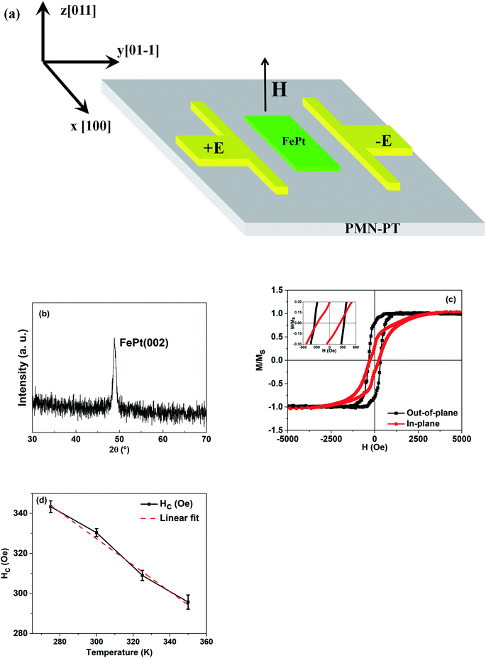
2.5 nm-FePt films were grown on the PMN–PT(011) substrate by magnetron sputtering at 400 °C with a base pressure less than 2 × 10⁻⁶ Pa. Continuously, FePt films were fabricated into Hall bar via standard lithography and Ar ion milling, the size of which is 20 × 120 μm, as shown in Fig. 1(a). The Pt electrodes are used to apply uniform E-field. Before each measurement, PMN–PT substrates were polarized by E-field of 15 kV cm−1.The surface roughness of the PMN–PT(011) substrates was measured by an atomic force microscope (AFM) and the magnetic properties of FePt films were obtained on a vibrating sample magnetometer (VSM). The crystal structure of the FePt films was analyzed via grazing incidence X-ray diffraction (GIXRD). Magnetization switching is detected by the MOKE microscope. RH–H and RH–I loops were measured on a physical property measurement system (PPMS) with Keithley 6221, 2400 and 2182A.
Results and discussion
The root mean square roughness value of the PMN–PT(011) substrate was measured by AFM, which is 0.51 nm (Fig. S1, ESI†). High quality surface of the PMN–PT(011) substrate guarantees the strain transfer efficiency from PMN–PT(011) to FePt films. The GIXRD pattern of the FePt films is shown in Fig. 1(b). The (002) peak of FePt can be observed at about 48.9°, which indicates the L10 phase and the [001] orientation of the FePt films. Fig. 1(c) demonstrates the M–H loops of FePt films at 275 K and Fig. 1(d) displays the out-of-plane coercivity as a function of varying temperatures for FePt films. The coercivity of FePt films has an obvious change, which decreases from 343 Oe to 295 Oe with the increase in temperature. The reduction of coercivity results from both the increase in thermal fluctuation and decrease in magnetic anisotropy energy with an increase in temperature.19 We can draw a conclusion that the L10-FePt films are obtained.For the sake of understanding the temperature assistance of PMA and SOT-based magnetization switching, the RH–H loops of L10-FePt films under different temperatures were measured, as shown in Fig. 2(a). Rectangular RH–H loops reconfirm FePt films have strong PMA in the whole temperature range. The coercivity Hc of RH–H loops decreases monotonically while temperature increases from 275 K to 350 K, which is the same as the coercivity change of Fig. 1(c) and indicates weak PMA at high temperatures. It is noteworthy to notice that there is a slight reduction in the change of the anomalous Hall resistance ΔRH with an increase in temperature (Fig. S2, ESI†), ΔRH is the out-of-plane magnetization of L10-FePt films,20 which decreases with the increase in temperature due to the increasing of thermal fluctuation and decreasing of magnetic anisotropy energy.19 Therefore, the corresponding ΔRH decreases with the increase in temperature. However, the temperature varies in a small range from 275 K to 350 K, which results in a slight reduction of ΔRH. For RH–I measurements, the external magnetic field Hx of 500 Oe and pulse current are applied along the [100] direction. The external magnetic field Hx is applied to overcome the Dzyaloshinskii–Moriya interaction (DMI) effective field HDMI, which leads to current-induced magnetization switching.21,22 The RH–I loops of L10-FePt films under different temperatures are presented in Fig. 2(b). While the temperature increases, the critical current density Jc reduces from 2.35 × 10¹¹ A m−2 to 2.12 × 10¹¹ A m−2, which can be explained by formula (1):21
 | (1) |
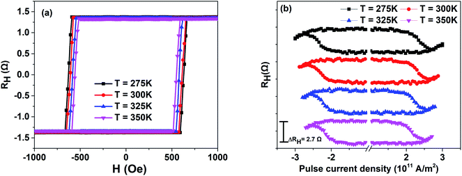 | ||
| Fig. 2 (a) RH–H loops of L10-FePt films under different temperatures. (b) RH–I loops of L10-FePt films with Hx = 500 Oe under different temperatures. | ||
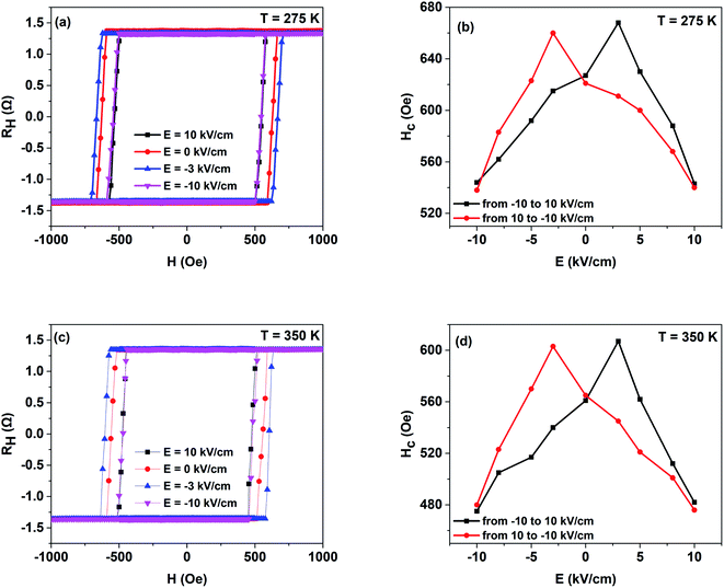
To survey the temperature assistance of the E-field controlled PMA of PMN–PT/FePt heterostructures, RH–H loops under varying E-field at 275 K were obtained, as shown in Fig. 3(a). E-field generates an apparent change in coercivity and ΔRH keeps still. Dependence of coercivity Hc on the applied E-field at 275 K is summarized in Fig. 3(b). Coercivity Hc varies along a butterfly shape loop, which presents a coercivity Hc change of 22.2% from 540 Oe (E = 10 kV cm−1) to 660 Oe (E = −3 kV cm−1) and indicates E-field controls PMA of PMN–PT/FePt heterostructures reversibility at 275 K. PMA of L10-FePt originates from both hybridization between Fe 3d and Pt 5d electrons and SOC.23 According to the piezoelectric properties under E-field reported by Peng and Li,13,24 when the E-field decreases from 10 kV cm−1 to −10 kV cm−1, L10-FePt films suffer compressive strain along the [01−1] direction at E = −3 kV cm−1. Consequently, L10-FePt films suffer compressive strain along the [011] direction and tensile strain along the [100] at E = −3 kV cm−1. The compressive strain along the [011] direction not only improves the chemical ordering parameter S of L10-FePt films, which results in stronger SOC, but also increases the hybridization between Fe 3d and Pt 5d.7,23,25,26 As a result, PMA and coercivity Hc are enhanced at E = −3 kV cm−1. Similarly, L10-FePt films suffer tensile strain at E = ±10 kV cm−1 along the [011] direction, which reduces the PMA and coercivity Hc. Then, Fig. 3(c) and (d) show the RH–H loops under varying E-field at 350 K and the dependence of coercivity Hc on applied E-field at 350 K, respectively. The coercivity Hc at 350 K also varies along a butterfly shape loop. However, compared with the change in coercivity Hc at 275 K, the coercivity Hc has a larger change of 32.3% from 476 Oe (E = 10 kV cm−1) to 603 Oe (E = −3 kV cm−1) at 350 K. Higher temperature enhances the piezoelectric coefficient of the PMN–PT(011) substrate and results in a large strain-induced effective field Hs under E-field, which is given by formula (2):27
 | (2) |
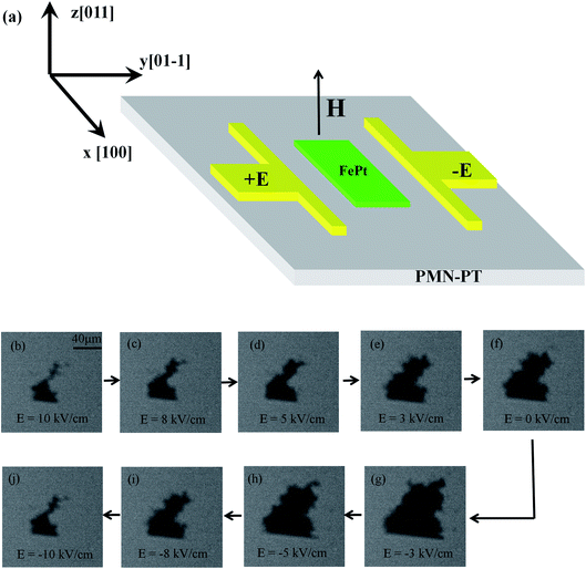
For verifying the E-field controlled PMA of PMN–PT/FePt heterostructures, we observe the magnetization switching of L10-FePt films under different E-fields directly by the MOKE microscope. Due to the restriction of the MOKE microscope, we can only observe the magnetization switching on rectangular L10-FePt films instead of Hall bar at 300 K. The MOKE measurement is schematically shown in Fig. 4(a). During the measurement, a fixed magnetic field of 367 Oe with perpendicular direction is applied, where the magnetization begins to switch. Compared with other magnetic fields (Fig. S3, ESI†), the magnetic field of 367 Oe enables us to observe the electric field-controlled magnetization switching clearly. Fig. 4(b)–(j) present the MOKE images of E-field-controlled magnetization switching of L10-FePt films. The white and black areas of MOKE images stand for the magnetization up and down, respectively. With the E-field scanning from 10 kV cm−1 to −10 kV cm−1, the small black area first apparently expands to maximum and then reduces to the original state, the magnetization direction of which is opposite to external magnetic field. According to the discussion above, the L10-FePt films suffer the tensile strain at E = ±10 kV cm−1 along the [011] direction, which reduces the PMA of L10-FePt films and makes the magnetization switch easily under the fixed magnetic field. Therefore, the area of magnetization down is small. The L10-FePt films suffer the compressive strain along the [011] direction at E = −3 kV cm−1. Compared with tensile strain, compressive strain exerts opposite effects on L10-FePt films, which enhances the PMA and expands the area of magnetization down. The magnetization switching observed by the MOKE microscope under different E-fields gives us a compelling evidence of the E-field-controlled PMA of PMN–PT/FePt heterostructures.
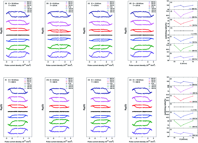
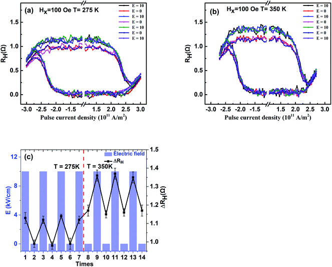
According to the discussion above, PMA of PMN–PT/FePt heterostructures can be manipulated more effectively by E-field at high temperatures. It is rational to explore temperature assistance of E-field-controlled SOT-based current induced magnetization switching of PMN–PT/FePt heterostructures. Fig. 5(a)–(d) show the RH–I loops of L10-FePt films with different Hx under varying E-field at 275 K. The RH–I loops with Hx of ±100 Oe and ±300 Oe show partial magnetization switching and RH–I loops with Hx of ±500 Oe show fully magnetization switching. When Hx is ±100 Oe or ±300 Oe, Hx < HDMI, the external magnetic field Hx is not sufficient to overcome the DMI effective field HDMI. Therefore, the current-induced magnetization cannot be switched totally. Fig. 5(e)–(k) summarize the dependence of the magnetization switching ratio on applied E-field with different Hx at 275 K. With the E-field scanning from 10 kV cm−1 to −10 kV cm−1, the magnetization switching ratio first decreases from 41.8% to 33.9% and then rises back to 41.2% and has a change of 21.5% with Hx of ±100 Oe at 275 K, and magnetization switching ratio with Hx of ±300 Oe at 275 K shows the same trend and has a change of 18.6%. However, magnetization switching ratio with Hx of ±500 Oe at 275 K does not change under different E-fields, which indicates the effects of strain on magnetization can be ignored with Hx of ±500 Oe. The compressive strain along the [011] direction at E = −3 kV cm−1 enhances PMA, which results in difficult magnetization switching and a small magnetization switching ratio. The tensile strain at E = ±10 kV cm−1 results in a large magnetization switching ratio. Fig. 5(l)–(o) show the RH–I loops of L10-FePt films with different Hx under varying E-field at 350 K. Fig. 5(p)–(v) summarizes the dependence of the magnetization switching ratio on applied E-field with different Hx at 350 K. Compared with change in the magnetization switching ratio induced by E-field at 275 K, the magnetization switching ratio has an improved change of 28.2% with Hx of ±100 Oe and an improved change of 27.2% with Hx of ±300 Oe at 350 K under applied E-field, which is attributed to the large strain-induced effective field Hs and weak PMA of L10-FePt films at 350 K. To check the stability of the Hall bar, Fig. 6(a) and (b) show the RH–I curves under alternate E-field with Hx of 100 Oe at 275 K and 300 K, respectively. Fig. 6(c) summarizes the dependence of ΔRH on alternate E-field with Hx of 100 Oe at 275 K and 300 K. The change of ΔRH is stable under alternate E-field at 275 K and 300 K, which suggests that the E-field modulated SOT-based current-induced magnetization switching of PMN–PT/FePt heterostructures is more effective and steady with small Hx at a high temperature.
An E-field controlled SOT-based logical circuit consists of two NOT gates and an output control “EN” is designed, which realize the bidirectional transmission of data, as shown in Fig. 7. Both Data1 and Data2 can be used as inputs or outputs. The Hall bar is regarded as the “EN”, which is a switch for NOT gates. When “EN” = 1, the NOT gate 1 is activated and outputs of red circuit are consistent with the logic of NOT gate 1, while the NOT gate 2 is deactivated. Continuously, when “EN” = 0, the NOT gate 2 is activated and outputs of blue circuit are consistent with the logic relationship of NOT gate 2, and the NOT gate 1 is deactivated. According to our studies mentioned above, when the Hx is 100 Oe and E-field is “on” (10 kV cm−1), ΔRH of the Hall bar is 1.13 Ω, which stands for the high electrical level and “EN” = 1. With “EN” = 1, the NOT gate 1 is activated. The data is transmitted from left to right and we can get Data2 = −Data1. On the contrary, when the E-field is “off” (0 kV cm−1), ΔRH of Hall bar is 0.99 Ω, which stands for the low electrical level and “EN” = 0. With “EN” = 0, the NOT gate 2 is activated. The data is transmitted from right to left and we can get Data1 = −Data2. Consequently, we summarize the outputs of the logical circuit, which depend on the inputs and “EN”, as shown in Table 1. We realize the bidirectional transmission of data with the help of the PMN–PT/FePt heterostructure. An E-field controlled SOT-based logical circuit can be widely used in computer, digital control, communication, automation and instrument.
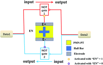 | ||
| Fig. 7 Schematic designs of an SOT-based logical circuit composed by two NOT gates and an output control “EN”, where the Hall bar is output control EN. | ||
| EN = 1 | EN = 0 | ||||
|---|---|---|---|---|---|
| Input D1 | 1 | 0 | Input D2 | 1 | 0 |
| Output D2 | 0 | 1 | Output D1 | 0 | 1 |
Conclusions
In conclusion, L10-FePt films were deposited on the PMN–PT(011) substrate. While the temperature increases, the coercivity Hc and critical current density Jc decrease monotonically because of the large strain-induced effective field Hs and weak PMA of L10-FePt films at 350 K, E-field has an improved regulating effect on PMA- and SOT-based current-induced magnetization switching of PMN–PT/FePt heterostructures. Magnetization switching observed by an MOKE microscope confirms that PMA can be controlled by E-field. In addition, change in the anomalous Hall resistance ΔRH is modulated reversibly by alternate E-field under different temperatures, which enables us realize an E-field-controlled SOT-based logical circuit and the bidirectional transmission of data. These new discoveries offer us an avenue to manufacture potential spintronic devices and technologies by the E-field modulation of PMN–PT/FePt heterostructures at different temperatures.Author contributions
These authors contributed equally to this work.Conflicts of interest
There are no conflicts to declare.Acknowledgements
This work was partially supported by National Natural Science Foundation of China (Grant No. 51901150), Research Project Supported by Shanxi Scholarship Council of China (HGKY2019083), Shanxi Provincial Key Research and Development Project (No. 201803D421046).References
- S. Fukami, C. Zhang, S. DuttaGupta, A. Kurenkov and H. Ohno, Nat. Mater., 2016, 15, 535 CrossRef CAS PubMed.
- A. Manchon and S. Zhang, Phys. Rev. B: Condens. Matter Mater. Phys., 2009, 79, 094422 CrossRef.
- Y. Cao, Y. Sheng, K. W. Edmonds, Y. Ji, H. Zheng and K. Wang, Adv. Mater., 2020, 32, 1907929 CrossRef CAS PubMed.
- J. Sinova, S. O. Valenzuela, J. Wunderlich, C. H. Back and T. Jungwirth, Rev. Mod. Phys., 2015, 87, 1213 CrossRef.
- L. Liu, C. F. Pai, Y. Li, H. W. Tseng, D. C. Ralph and R. A. Buhrman, Science, 2012, 336, 555 CrossRef CAS PubMed.
- P. He, L. Ma, Z. Shi, G. Y. Guo, J. G. Zheng, Y. Xin and S. M. Zhou, Phys. Rev. Lett., 2012, 109, 066402 CrossRef CAS PubMed.
- M. Tang, K. Shen, S. Xu, H. Yang, S. Hu, W. Lu, C. Li, M. Li, Z. Yuan, S. J. Pennycook, K. Xia, A. Manchon, S. Zhou and X. Qiu, Adv. Mater., 2020, 32, 2002607 CrossRef CAS PubMed.
- A. Chernyshov, M. Overby, X. Liu, J. K. Furdyna, Y. Lyanda-Geller and L. P. Rokhinson, Nat. Phys., 2009, 5, 656 Search PubMed.
- X. Chen, X. Zhou, R. Cheng, C. Song, J. Zhang, Y. Wu, Y. Ba, H. Li, Y. Sun, Y. You, Y. Zhao and F. Pan, Nat. Mater., 2019, 18, 931 CrossRef CAS PubMed.
- T. Nan, J. Hu, M. Dai, S. Emori, X. Wang, Z. Hu, A. Matyushov, L. Chen and N. Sun, Adv. Funct. Mater., 2018, 29, 1806371 CrossRef.
- Q. Wang, J. Domann, G. Yu, A. Barra, K. L. Wang and G. P. Carman, Phys. Rev. Appl., 2018, 10, 034052 CrossRef CAS.
- C. Thiele, K. Dörr, O. Bilani, J. Rödel and L. Schultz, Phys. Rev. B: Condens. Matter Mater. Phys., 2007, 75, 054408 CrossRef.
- J. Peng, H. S. Luo, D. Lin, H. Q. Xu, T. H. He and W. Q. Jin, Appl. Phys. Lett., 2004, 85, 6221 CrossRef CAS.
- Y. Xiang, P. Zhou, Y. Qi, K. Liang, Z. Ma, Y. Liu, Z. Yan, P. Du, R. Xiong, Y. Liu, Z. Xia, M. Popov, D. Filippov, J. Zhang, G. Srinivasan and T. Zhang, J. Magn. Magn. Mater., 2020, 514, 167138 CrossRef CAS.
- K. Cai, M. Yang, H. Ju, S. Wang, Y. Ji, B. Li, K. W. Edmonds, Y. Sheng, B. Zhang, N. Zhang, S. Liu, H. Zheng and K. Wang, Nat. Mater., 2017, 16, 712–716 CrossRef CAS PubMed.
- M. Yang, Y. Deng, Z. Wu, K. Cai, K. W. Edmonds, Y. Li, Y. Sheng, S. Wang, Y. Cui, J. Luo, Y. Ji, H. Z. Zheng and K. Wang, IEEE Electron Device Lett., 2019, 40, 1554–1557 CAS.
- S. Chen, D. Li, B. Cui, L. Xi, M. Si, D. Yang and D. Xue, J. Phys. D: Appl. Phys., 2018, 51, 095001 CrossRef.
- G. J. Lim, W. L. Gan, W. C. Law, C. Murapaka and W. S. Lew, J. Magn. Magn. Mater., 2020, 514, 167201 CrossRef CAS.
- T. Shima, K. Takanashi, Y. K. Takahashi and K. Hono, Appl. Phys. Lett., 2004, 85, 2571 CrossRef CAS.
- M. Chen, Z. Shi, W. J. Xu, X. X. Zhang, J. Du and S. M. Zhou, Appl. Phys. Lett., 2011, 98, 082503 CrossRef.
- W. B. Liao, T. Y. Chen, Y. C. Hsiao and C. F. Pai, Appl. Phys. Lett., 2020, 117, 182402 CrossRef CAS.
- M. Tang, K. Shen, S. Xu, H. Yang, S. Hu, W. Lu, C. Li, M. Li, Z. Yuan, S. J. Pennycook, K. Xia, A. Manchon, S. Zhou and X. Qiu, Adv. Mater., 2020, 32, 2002607 CrossRef CAS PubMed.
- A. M. Zhang, X. S. Wu, S. L. Tang and S. M. Zhou, Chem. Phys. Lett., 2016, 654, 135 CrossRef CAS.
- F. Li, S. J. Zhang, Z. Xu, X. Y. Wei, J. Luo and T. R. Shrout, Appl. Phys. Lett., 2010, 96, 192903 CrossRef PubMed.
- L. J. Zhu, D. Pan and J. H. Zhao, Phys. Rev. B: Condens. Matter Mater. Phys., 2014, 89, 220406 CrossRef.
- B. Peng, Z. Zhou, T. Nan, G. Dong, M. Feng, Q. Yang, X. Wang, S. Zhao, D. Xian, Z. De Jiang, W. Ren, Z. G. Ye, N. X. Sun and M. Liu, ACS Nano, 2017, 11, 4337–4345 CrossRef CAS PubMed.
- B. M. Zhang, J. S. Chen and G. M. Chow, IEEE Trans. Magn., 2011, 47, 2823–2826 Search PubMed.
- W. J. Zhu, Y. W. Liu and C. G. Duan, Appl. Phys. Lett., 2011, 99, 032508 CrossRef.
- J. M. Vargas and J. Gómez, APL Mater., 2014, 2, 106105 CrossRef.
Footnote |
| † Electronic supplementary information (ESI) available. See DOI: 10.1039/d1ra00919b |
| This journal is © The Royal Society of Chemistry 2021 |

