 Open Access Article
Creative Commons Attribution 3.0 Unported Licence
H2O2 production on a carbon cathode loaded with a nickel carbonate catalyst and on an oxide photoanode without an external bias†
Soichi Takasugi a,
Yugo Miseki
 a,
Yoshinari Konishi
 a,
Kotaro Sasaki
 b,
Etsuko Fujita
 b and
Kazuhiro Sayama
 *a
*a
aGlobal Zero Emission Research Center (GZR), National Institute of Advanced Industrial Science and Technology (AIST), Central 5, 1-1-1 Higashi, Tsukuba, Ibaraki 305-8565, Japan. E-mail: k.sayama@aist.go.jp
bChemistry Division, Brookhaven National Laboratory, Upton, New York 11973-5000, USA
First published on 17th March 2021
Abstract
Efficient H2O2 production both on a carbon cathode modified with various metal salts and on an oxide photoanode was investigated. The cathodic current density and faradaic efficiency for H2O2 production (FE(H2O2)) on a carbon cathode in KHCO3 aqueous solution were significantly improved by the loading of an insoluble nickel carbonate basic hydrate catalyst. This electrode was prepared by a precipitation method of nickel nitrate and KHCO3 aqueous solution at ambient temperature. The nickel carbonate basic hydrate electrode was very stable, and the accumulated concentration of H2O2 was reached at 1.0 wt% at a passed charge of 2500C (the average FE(H2O2) was 80%). A simple photoelectrochemical system for H2O2 production from both the cathode and a BiVO4/WO3 photoanode was demonstrated without an external bias or an ion-exchange membrane in a one-compartment reactor under simulated solar light. The apparent FE(H2O2) from both electrodes was calculated to be 168% in total, and the production rate of H2O2 was approximately 0.92 μmol min−1 cm−2. The solar-to-chemical energy conversion efficiency for H2O2 production (STCH2O2) without an external bias was approximately 1.75%.
Introduction
Hydrogen peroxide (H2O2) is an environmentally friendly and important chemical oxidant that has been widely applied to pulp bleaching, waste treatment, chemical synthesis of peroxides, and food sterilization.1–8 The anthraquinone redox process using H2 and O2 gases has been used for the industrial large-scale production of H2O2.2,9 However, there are many problems in this process: a large amount of energy requirement and H2 consumption in the complicated system producing a huge amount of CO2 emission, the usage of harmful organic solvents, the requirement of concentration, and transformation from the central process to consumption area. Therefore, some distributed and small-scale electrochemical H2O2 production processes in aqueous solution have been widely investigated.5,10–22 The on-site electrochemical process has many advantages, such as safety without H2 usage, no organic solvent separation, and controllability on the production amount and concentration for demand. Two kinds of reactions for H2O2 production are present in the electrochemical process: reductive H2O2 production from O2 on a cathode (eqn (1)), and oxidative H2O2 production from H2O on an anode (eqn (2)).There are many reports on the reductive H2O2 production from O2.23–30 In contrast, the oxidative H2O2 production and accumulation from H2O are very difficult. However, we and others have reported that H2O2 can be accumulated when KHCO3 aqueous solution is used in electrochemical and photoelectrochemical processes.19–22,31–35 It is advantageous and highly efficient to produce H2O2 on both electrode sides by combining the cathodic and anodic reactions, as shown in eqn (3), compared to the production on each electrode side under the same electric charge. The apparent faradaic efficiency for the H2O2 production (FE(H2O2)) could reach 200% in total (100% + 100%) if the production occurred on both sides of the electrode.36 We have previously demonstrated that the H2O2 production can take place on a BiVO4/WO3 photoanode and an Au cathode at near-neutral pH in KHCO3 aqueous solution using a simple one-compartment cell without an external bias, as shown in Fig. 1.19 The apparent faradaic efficiency was 140% in total (FE(H2O2) = 90% and 50% on the Au cathode and the BiVO4/WO3 photoanode, respectively). The band gap of BiVO4 is 2.4 eV, and the theoretical maximum photocurrent is reported to be 7.5 mA cm−2.37 Unfortunately, the current density of the Au cathode, a novel metal electrode, was low (−0.18 mA cm−2 at +0.5 V (vs. RHE)). Therefore, improved systems are needed for practical applications.
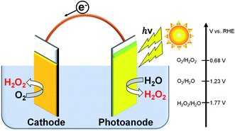 | ||
| Fig. 1 H2O2 production on both electrode sides in a one-compartment cell under illumination without an external bias or an ion-exchange membrane. | ||
Cathode reaction:
| O2 + 2H+ + 2e− → H2O2, E(O2/H2O2) = +0.68 V (vs. RHE) | (1) |
Anode reaction:
| 2H2O → H2O2 + 2H+ + 2e−, E(H2O2/H2O) = +1.77 V (vs. RHE) | (2) |
| 2H2O + O2 → 2H2O2 two-electron process | (3) |
As for noble-metal-free cathodes, there are several reports on the use of carbon-based materials modified with inexpensive metal compounds mainly at basic pH.38–41 However, efficiencies for the H2O2 production with these cathodes were low at near-neutral pH, and an ion-exchange membrane was essential when the pH values of the anodic and cathodic electrolyte solutions were different.21,22 Recently, we reported that a carbon cathode modified with a biomass-derived W-based electrocatalyst exhibited a relatively high cathodic current for the reductive H2O2 production in a near-neutral KHCO3 aqueous solution in a two-compartment cell, but the FE(H2O2) and the partial current density for H2O2 production were not enough.20
In this paper, we pursued developing more efficient H2O2 production systems on a photoanode and a noble-metal-free cathode in a KHCO3 aqueous solution without an ion-exchange membrane or an external bias in a one-compartment cell. The system using a single electrolyte in a one-compartment cell without any membrane is very simple. It was found that nickel carbonate on a carbon-based cathode showed excellent electrocatalytic activity on both FE(H2O2) and the partial current density for H2O2 production in a KHCO3 solution. A water-insoluble nickel carbonate electrocatalyst was easily prepared in situ from a nickel salt and KHCO3 aqueous solution at ambient and mild conditions. The apparent solar-to-chemical energy conversion efficiency for H2O2 production (STCH2O2) on a combination system of the BiVO4/WO3 photoanode and the cathode loaded with nickel carbonate electrocatalyst without external bias reached 1.75%, which is the highest among all reported values so far.
Experimental section
Fabrication of the carbon cathode loaded with various metals
A water-repellent-treated carbon paper (abbreviated as CP; 1.0 cm2, TORAY, TGP-H-090) was used as the substrate plate of the cathode. A conductive carbon powder of Ketjenblack EC600JD (abbreviated as KB; Lion Specialty Chemicals Co., Ltd.)42–44 was used with various electrocatalysts on CP. KB powder loaded with various metal salts as an electrocatalyst (abbreviated as Met/KB) was prepared by an impregnation method. The metal salts used were Cr(II) nitrate nonahydrate, Mn(II) nitrate tetrahydrate, Fe(III) nitrate nonahydrate, Co(II) nitrate hexahydrate, Ni(II) nitrate hexahydrate, Cu(II) nitrate trihydrate, Zn(II) nitrate hexahydrate, Ga(III) nitrate n-hydrate, hexaammonium heptamolybdate tetrahydrate, and ammonium tungstate para-pentahydrate (purchased from Fujifilm Wako Pure Chemicals Corporation).A mixture of 100 mg of KB powder and 0–1000 mg of various metal salts was added to 20 mL of H2O. The suspension was thoroughly dispersed by ultrasonication for 30 min and dried overnight in a heating oven at 353 K under an ambient pressure. The ratio of a loaded metal salt of x wt% to the weight of the KB powder was abbreviated as Metx/KB. For example, a loaded metal salt of 10 and 100 wt% vs. the weight of the KB powder were abbreviated as Met10/KB and Met100/KB, respectively. A mixture of 1.5 mg (standard amount) of the electrocatalyst (KB, Met/KB) and 0.75 mg of 20 wt% Nafion solution (Sigma-Aldrich Co., USA) was dispersed in 0.5 mL of ethanol, and loaded on one side of the CP substrate (area 1.0 cm2) at room temperature. This cathode loaded with an electrocatalyst and KB powder on CP was dried at 333 K for 30 min in a heating oven.
HNO3 treatment for KB powder
HNO3-treated KB powder (abbreviated as KBHNO3) was prepared by an immersion process. To 38.3 g of concentrated HNO3 aqueous solution (60%, Fujifilm Wako Pure Chemical Corporation), 1000 mg of KB powder was added. The suspension was thoroughly heated at 353 K for 24 h with a string at 300 rpm in a heating oven. They were collected by suction filtration and thoroughly washed with distilled water. Metal-salt loading on KBHNO3 (abbreviated as Met/KBHNO3) was prepared and coated on CP as the cathode by the same process.Fabrication of the BiVO4/WO3 photoelectrode
The BiVO4/WO3 photoelectrode used in this study was synthesized using the method previously reported by Fuku,45 and was prepared on a F-doped SnO2 (FTO) glass substrate by spin-coating method. The precursor of the WO3 layer was loaded by spin coating (1000 pm, 15 s, 200 μL per 12 cm2) on FTO, and then calcined at 773 K for 30 min. Spin coating of the WO3 layer was repeated twice using N,N-dimethylformamide (DMF) solutions of tungsten hexachloride (WCl6, 4 N; Kojundo Chemical Laboratory, Co., Ltd.) adjusted to 504 and 252 mM for the first and second coat, respectively. The BiVO4 layer was also fabricated by spin coating (500 rpm, 15 s, 400 μL per 12 cm2) on the WO3 layer, and calcined at 773 K for 30 min. The spin coating of the BiVO4 layer was repeated three times using 0.4 or 0.6 M BiVO4 precursor solution. The first layer of BiVO4 used 0.4 M BiVO4 precursor solution, and the rest of the layer used 0.6 M solution. The BiVO4 precursor solution, adjusted to 100 mM, was prepared by dissolving bismuth oxide (BiO1.5) solution (Symmetrix Co., USA) and a vanadium oxide (VO2.5) solution (Symmetrix Co., USA) in butyl acetate with a Bi/V molar ratio of 1.0. To the BiVO4 solution, 10 wt% butyl acetate solution of ethyl cellulose was added as a thickening agent with a (BiVO4 solution)/(ethyl cellulose solution) volume ratio of 1.5.Electrochemical measurements and quantification method
Electrochemical measurement on the cathode
The electrochemical properties of the electrocatalyst cathode were evaluated in a 2.0 M KHCO3 aqueous solution (pH 8.8) with O2 bubbling (50 mL min−1) with an ice bath (273–278 K) by using an electrochemical analyzer (Hokuto Denko, HZ-7000). The current–potential (I–E) characteristics were measured via a three-electrode method using a two-compartment cell. The scan rate was set at 2 mV s−1. The volume of the electrolyte solutions of the anode and cathode chambers was 35 mL with stirring. The reference electrode used was 3 M Ag/AgCl, and the counter electrode was a Pt wire. Between the anode and cathode chambers, Aciplex (Asahi KASEI) was used as an ion-exchange resin. After the reaction was completed, 1.1 mL of the reaction solution was taken out using a syringe. The schematic illustration of a two-compartment cell is shown in Fig. S1(a).† All potentials in this paper were quoted with respect to the reversible hydrogen electrode (RHE), according to the Nernst equation (eqn (4)).| E(vs. RHE) = E(vs. Ag/AgCl) + 0.0591 × pH + 0.197 | (4) |
An accumulation experiment for H2O2 was conducted at a constant applied bias of +0.5 V vs. RHE.
Simultaneous H2O2 production on both the photoanode and cathode without an external bias or membrane
The simultaneous production of H2O2 from H2O oxidation at the photoanode and O2 reduction at the cathode was performed without applying any external bias using a two-electrode system composed of a BiVO4/WO3 photoanode (irradiation area of 0.2 cm2 with a white board behind the photoanode) and a Ni10/KBHNO3 cathode (catalyst loading 1.5 mg cm−2, area 0.2 cm2). An aqueous solution of KHCO3 (2.0 M) was used as an electrolyte (200 mL), and CO2 and O2 gases were each bubbled for 50 mL min−1 into the one-component cell with a pH value of 8.0 in an ice bath (273–278 K). An ice bath was used under CO2 bubbling to obtain the optimum reaction conditions for the stability of the photoanode. It was confirmed that O2 gas diffusion is not the rate-limiting factor under our conditions of <10 mA cm−2. A solar simulator calibrated to AM 1.5G (1 SUN, 0.1 W cm−2) was used as the light source. The schematic illustration of our reaction system in a one-compartment cell without membrane is shown in Fig. S1(b).†Characterization and quantification method
The prepared electrodes were characterized by X-ray fluorescence (XRF, Rigaku, Super mini200) measured in a vacuum with a wavelength dispersive spectrometer with Pd–K radiation. The crystal structures of the samples were investigated by X-ray diffraction (XRD, Malvern Panalytical, Empyrean) using Cu Kα radiation at 40 kV and 40 mA. Transmission electron microscopy and energy dispersive X-ray spectroscopy (TEM and EDS, Philips, Tecnai Osiris) measurements were carried out with a field emission gun operating at 200 kV.The amount of produced H2O2 was quantified via UV-visible spectroscopy (TECAN, Infinite 200 PRO). Then, 1.0 mL of sample was added to 0.9 mL of 3.0 M HCl aqueous solution and 0.1 mL of FeCl2 in 1.0 M HCl aqueous solution and quantified from Fe3+ colorimetry (λ = 330 nm), as we reported previously.19,20,32,44 The faradaic efficiency for H2O2 production (FE(H2O2)) was calculated using eqn (5):
| FE(H2O2)% = [amount of produced H2O2] × 100 × 2/[amount of passed electrons] | (5) |
We confirmed that the error range of the FE(H2O2) value was around ±2%.
The apparent partial current density for H2O2 production at a constant potential (Jap(H2O2)) was calculated using eqn (6):
| Jap(H2O2) = J(Total) × FE(H2O2) | (6) |
The turnover number was calculated using eqn (7). The amount of nickel was measured by XRF.
| Turnover number = [amount of produced H2O2 (in moles)]/[amount of nickel (in moles)] | (7) |
The apparent solar-to-chemical energy conversion efficiency (STC) for the H2O2 and O2 production on the BiVO4/WO3 photoanode (irradiation area of 0.2 cm2 with a white board behind the photoanode) and on the Ni10/KBHNO3 cathode (catalyst loading 1.5 mg cm−2, area 0.2 cm2) was calculated using eqn (8):35
| STCH2O2(%) = [(VH2O2 × ΔG) × 100]/Int | (8) |
Results and discussion
Table 1 shows the J(Total) and the FE(H2O2) through a O2 reduction reaction on the KB/CP substrate cathodes modified with various metal salts (Met100/KB and Met10/KB, 100 and 10 wt% of metal salt in KB powder) in a 2.0 M KHCO3 aqueous solution under O2 bubbling condition. Here, FE(H2O2) and Jap(H2O2) were evaluated at the passed charge after 5C at +0.5 V. The J(Total) of the CP substrate was negligibly small. On the other hand, the J(Total) largely increased when KB powder was loaded on the CP substrate. KB powder has a high surface area (1270 m2 g−1) and high conductivity.47 It was surmised that the electron could be transferred through the conductive KB powder network, and that the reduction for H2O2 production could take place on the KB surface. The optimum loading amount of KB powder on the CP substrate was around 1.5 mg cm−2, and the current did not increase by further loading (Fig. S2†). The exfoliation of the powder from the CP substrate was observed by overloading (Fig. S2d†). Therefore, the loading amount of Met10/KB and Met100/KB on the CP substrate was fixed at 1.5 mg cm−2 in all experiments. The values of J(Total), FE(H2O2) and Jap(H2O2) were changed by the modification of various metal salts on the KB cathode. FE(H2O2) decreased by modification of Fe, Cu, Cr, Mn, Co, Ga, or W, compared to pristine KB powder and increased by modification with Mo100/KB, Ni100/KB, Ni10/KB, Zn100/KB, and Zn10/KB. As for the J(Total), most of the total current was improved by modification of these metal salts. The two-electron reduction for the H2O2 production reaction from O2 (eqn (1)) was competitive with other undesirable reactions: four-electron reduction of O2 to H2O (eqn (9)) and successive reduction of H2O2 to H2O (eqn (10)).| O2 + 4H+ + 4e− → 2H2O, E(O2/H2O) = +1.23 V (vs. RHE) | (9) |
| H2O2 + 2H+ + 2e− → 2H2O, E(H2O2/H2O) = +1.77 V (vs. RHE) | (10) |
| Met/KBa | FE(H2O2)b/% | J(Total)c/mA cm−2 | Jap(H2O2)/mA cm−2 |
|---|---|---|---|
| a Met100/KB or Met10/KB: various metal salts loaded on KB powder (100 or 10 wt% of the loading amount of precursor metal salt (Met) vs. KB powder).b The FE(H2O2) was measured at the passed charge after 5C.c The J(Total) was measured at a constant potential of +0.5 V (vs. RHE). | |||
| CP substrate only | — | 5.4 × 10⁻⁴ | — |
| KB | 59 | −4.0 | −2.4 |
| Fe100/KB | 4 | −11.5 | −0.4 |
| Fe10/KB | 13 | −10.5 | −1.4 |
| Cu100/KB | 9 | −8.5 | −0.8 |
| Cu10/KB | 42 | −8.5 | −3.6 |
| Cr100/KB | 32 | −5.1 | −1.6 |
| Cr10/KB | 43 | −6.2 | −2.9 |
| Mn100/KB | 1 | −4.2 | −0.04 |
| Mn10/KB | 3 | −5.2 | −0.2 |
| Co100/KB | 20 | −3.3 | −0.7 |
| Co10/KB | 15 | −8.9 | −1.3 |
| Ga100/KB | 54 | −3.5 | −1.9 |
| Ga10/KB | 56 | −5.4 | −3.0 |
| W100/KB | 33 | −4.6 | −1.5 |
| W10/KB | 44 | −6.9 | −3.0 |
| Mo100/KB | 36 | −3.7 | −1.3 |
| Mo10/KB | 67 | −5.0 | −3.4 |
| Ni100/KB | 66 | −5.3 | −3.5 |
| Ni10/KB | 85 | −8.1 | −6.9 |
| Zn100/KB | 71 | −4.4 | −3.1 |
| Zn10/KB | 65 | −6.9 | −4.5 |
The theoretical reduction potentials of the four-electron reduction of O2 (+1.23 V, eqn (9)) and successive reduction of H2O2 (+1.77 V, eqn (10)) were significantly positive compared to that of H2O2 production via two-electron reduction of O2 (+0.68 V, eqn (1)). In the case of the J(Total) improvement with decreasing FE(H2O2), the Jap(H2O2) was not significantly improved. It was surmised that these undesirable reactions might be accelerated by the modification of these metal nitrates or ammonium salt of Cu, Cr, Mn, Co, Ga, W, and Mo. On the other hand, the J(Total) and FE(H2O2) were both increased when Ni or Zn nitrate was modified. In particular, the Ni10/KB cathode showed the highest performance of Jap(H2O2) on the H2O2 production (−6.9 mA cm−2) among all metal salts in Table 1. The Jap(H2O2) was also improved by modification of all various Ni salts (nitrate, sulfate, acetate, chloride, Ni oxide, Ni hydroxide, and nickel carbonate (Table S1,† 10 wt% of Ni salt)), suggesting that the positive effect of the current density and the FE(H2O2) was caused mainly by the presence of Ni salt itself, rather than by the effect of anions. Ni nitrate showed the highest activity among them. Then, Ni nitrate was mainly used as a precursor for loading to a carbon electrode for subsequent experiments. An improved effect of the NiO-loaded KB cathode was not obvious compared to those with other nickel salts. NiO particles are hardly soluble in aqueous solution. In the case of soluble nickel-salts loaded KB cathodes, their properties were positively changed through the process of dissolution and precipitation. In the case of NiO, the bulk of NiO may be not changed in KHCO3 solution.
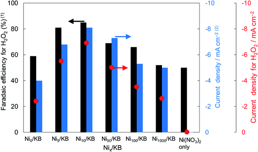
Fig. 2 shows the dependence of the loading amount of Ni nitrate over the KB cathode on FE(H2O2), J(Total), and Jap(H2O2). All values of the FE(H2O2), J(Total), and Jap(H2O2) showed volcano shape profiles, depending on the amount of Ni nitrate modification, and had the best values at 10 wt% of Ni nitrate on the KB cathode (Ni10/KB). As for the Ni-nitrate-loaded cathode without KB powder (the rightmost data in Fig. 2), the J(Total) and the Jap(H2O2) were very small, while the FE(H2O2) was equivalent to pristine KB powder. The current–potential dependences of some typical cathodes with and without Ni nitrate are shown in Fig. 3. It was surmised that the loaded nickel compound itself on the CP substrate might be hardly conductive, and the excess amount of Ni compound hindered the electron transfer though the network of the conductive KB.
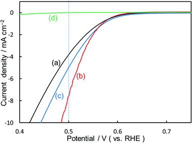 | ||
| Fig. 3 I–E curves of (a) pristine KB powder, (b) Ni10/KB cathode, (c) Ni100/KB cathode, (d) Ni nitrate only without KB powder at a scan rate of 2 mV s−1. | ||
The TEM and EDX images of Ni10/KB are shown in Fig. 4. The Ni10/KB sample was prepared by immersion in KHCO3 electrolyte. Although it was difficult to recognize the clear particle shapes of the Ni compounds based on a TEM image only, the presence of a small aggregation of Ni element was confirmed by TEM-EDX image analysis. The aggregation size of the Ni compounds was approximately 10–40 nm in the EDX mapping images. On the other hand, when a larger amount of Ni was loaded (Ni100/KB), a large aggregation (>0.5 μm) of the Ni element was observed by SEM-EDX measurements (Fig. S3†). It was speculated that the large aggregation of the Ni compounds might decrease the current density at a higher loading amount of Ni(NO3)2 ≧ 50 wt% in Fig. 2.
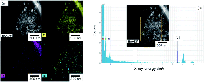 | ||
| Fig. 4 Ni10/KB images: (a) HAADF-TEM image and element mapping images of EDX. (b) EDX spectrum and analysis area (yellow square). | ||
The Ni amount with KB powder (Ni10/KB and Ni100/KB) measured by XRF before and after washing with distilled water or KHCO3 aqueous solutions is shown in Table 2. The Ni signal by XRF before the washing process completely disappeared after washing with distilled water. On the other hand, after washing with KHCO3 aqueous solution, the Ni signal was clearly detected, and more than 80% of Ni remained on the KB cathode. Ni(NO3)2 is easily dissolved in water, while nickel carbonates have a very poor water solubility (solubility product (pKsp) = 11.2).48 Actually, the green transparent aqueous solution of Ni(NO3)2 changed to colorless by the addition of KHCO3, and insoluble green powders were precipitated (Fig. S4†). The positive effect of Ni loading on the I–E curve disappeared by washing with distilled water, not by washing with a bicarbonate solution (Fig. S5†). Moreover, the presence of Ni species on the surfaces of the cathodes was also investigated by XPS (Fig. S6†). The peaks of the spectrum of Ni2p3/2 and Ni2p5/2 were observed on Ni10/KB (a) before and (b) after washing with KHCO3 aqueous solution. However, they were not observed (c) after washing with distilled water. While the apparent surface coverage of Ni compounds to carbon before washing with KHCO3 aqueous solution as calculated by XPS intensity was not large (less than 1%), the exact Ni coverage was difficult to estimate due to the low sensitivity and presence of carbon impurities.
| Pristine KB | Ni10/KB | Ni100/KB | |
|---|---|---|---|
| Amount of Ni/μg cm−2 | |||
| Before washing | 0 | 2.6 | 24.5 |
| Washing with distilled water | 0 | 0 | 0 |
| Washing with 2.0 M KHCO3 | 0 | 2.3 | 20.2 |
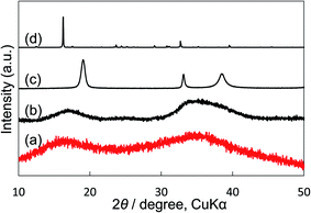
We compared our electrocatalyst powder sample with reference reagents of nickel(II) carbonate basic hydrate (NiCO3·2Ni(OH)2·4H2O; Fujifilm Wako Pure Chemical Corporation, 44% as Ni), nickel(II) hydroxide (Ni(OH)2; Fujifilm Wako Pure Chemical Corporation, 95%) and nickel(II) nitrate hexahydrate (Ni(NO)2·6H2O; Fujifilm Wako Pure Chemical Corporation, 99.9%) using XRD and thermogravimetric-differential thermal analysis (TG-DTA). Our synthetic powder sample was prepared by immersing Ni(NO3)2 in a KHCO3 aqueous solution. As shown in the XRD patterns (Fig. 5), the shape and the broad peak position at around 17° and 35° of our powder sample were similar to those of the reference nickel carbonate rather than Ni(OH)2. In the TG-DTA results (Fig. S7†), the curves of TG and DTA of our electrocatalyst sample (a) were very similar to those of the reference reagent of NiCO3·2Ni(OH)2·4H2O (b), but different from those of Ni(OH)2 (c) and Ni(NO)2·6H2O (d). Therefore, it was concluded that the loaded Ni(NO3)2 on the KB cathode was immediately changed to insoluble nickel(II) carbonate basic hydrate when the cathode electrode was soaked in a KHCO3 solution, and that the small particles (10–40 nm) of Ni carbonate formed by this process can function as an excellent catalyst for H2O2 production on the KB cathode. This simple preparation of the insoluble electrocatalyst at ambient conditions is a significant advantage for practical applications.
We confirmed that the H2O2 production properties on FE(H2O2) and Jap(H2O2) over Ni10/KB were almost the same as those over pristine KB in KOH and potassium hydrogen phosphate aqueous solution, suggesting that a positive nickel salt effect was not observed in KOH and potassium hydrogen phosphate aqueous solution, in contrast with the KHCO3 aqueous solution. The particle of nickel carbonate basic hydrate was stable and insoluble in KOH (pH > 14) and potassium hydrogen phosphate (pH > 8.5, which is the same as KHCO3) aqueous solution. The surface condition is very important for electrocatalytic reactions. The loaded Ni(OH)2 on KB could show a positive effect in KHCO3 aqueous solution, as shown in Table 1. It was confirmed using XPS measurement that the surface carbonate was reduced after the immersion in KOH or potassium hydrogen phosphate aqueous solution. From all results, it is speculated that the nickel adsorbed with carbonate, rather than nickel element itself, on the outermost surface and at the interface of the loaded electrocatalyst with KB possibly being the active site for H2O2 production.
It has been reported that the activity of a carbon-based cathode for H2O2 production from O2 could be improved by nitric acid treatment, where the carbon surface was changed in concentrated nitric acid for a long time at high temperature.49,50 Therefore, we tried to combine nitric acid treatment and Ni carbonate effect on the KB cathode (abbreviated as Ni/KBHNO3). Table 3 shows the J(Total), FE(H2O2), and Jap(H2O2) for the O2 reduction reaction to H2O2 on KBHNO3 and Ni10/KBHNO3. All values of the FE(H2O2), J(Total), and Jap(H2O2) of KBHNO3 were improved by the nitric acid treatment compared to those when the pristine KB was used. Moreover, the J(Total) and Jap(H2O2) of KBHNO3 were improved by the loading of Ni carbonate (Ni10/KBHNO3), and the Jap(H2O2) reached −9.8 mA cm−2 at +0.5 V vs. RHE. The J(Total) and Jap(H2O2) of Ni10/KBHNO3 were higher compared to those of Ni10/KB, suggesting the synergistic effect of nitric acid treatment and Ni carbonate catalyst.
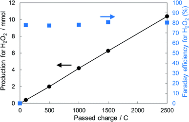
Fig. 6 shows the dependence of the FE(H2O2) on the applied potentials for Ni10/KBHNO3. The FE(H2O2) increased with the applied potential positively, and this behavior was similar to those in previous reports of carbon-based cathodes in KOH.51 The highest FE(H2O2) at 5C was 82–84% at around +0.5 to +0.6 V (vs. RHE). We also measured faradaic efficiency by the rotating ring disk electrode (RRDE) method (Fig. S8†), and found that the value of the FE(H2O2) by the RRDE method was 85% at +0.5 V (vs. RHE), which was almost consistent with the results of the accumulated H2O2 after passing 5C electrons of using a Fe3+ colorimetry method. The production rates of H2O2 on Ni10/KBHNO3 at +0.5 and +0.2 V (vs. RHE) were 121.9 and 330.3 mmol L−1 h−1 g−1 cm−2, respectively. To the best of our knowledge, these rates for reductive H2O2 production were the highest among all reports on noble-metal-free cathodes in aqueous solutions having near-neutral pH (Table S2†). Fig. 7 shows the long-term evaluation result of H2O2 production on the Ni10/KBHNO3 cathode with large amounts of passed charge. H2O2 production was increased linearly at a constant applied bias at +0.5 V (vs. RHE), and the FE(H2O2) was around 80% passing charges up to 2500C, suggesting that the produced H2O2 was not further reduced to H2O sequentially (eqn (10)) for a long term. From the linear production and the agreement of the FE(H2O2) by colorimetry and RRDE methods for long- and short-term quantitative measurements, respectively, we concluded that the total H2O2 selectivity was determined by the initial H2O2 selectivity on the cathode with the electrocatalyst. The amount of the produced H2O2 was 10.4 mmol and the amount of nickel was 0.037 μmol cm−2 (calculated from XRF) using Ni10/KBHNO3. Therefore, the turnover number was calculated as more than 14![[thin space (1/6-em)]](https://www.rsc.org/images/entities/char_2009.gif) 000 from eqn (7). The H2O2 accumulation concentration reached 1.0 wt% in 35 mL of 2.0 M KHCO3 aqueous solution. In addition, the I–E curves of the cathode hardly changed even after repeated 150 cycles of I–E measurements during 36 h (Fig. S9†), and the cathodic current remained around −11 mA cm−2, suggesting that the modification effect of the Ni10/KBHNO3 cathode was very stable under the H2O2 production conditions.
000 from eqn (7). The H2O2 accumulation concentration reached 1.0 wt% in 35 mL of 2.0 M KHCO3 aqueous solution. In addition, the I–E curves of the cathode hardly changed even after repeated 150 cycles of I–E measurements during 36 h (Fig. S9†), and the cathodic current remained around −11 mA cm−2, suggesting that the modification effect of the Ni10/KBHNO3 cathode was very stable under the H2O2 production conditions.
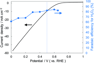 | ||
| Fig. 6 I–E curves for Ni10/KBHNO3 (area 1 cm2) at a scan rate of 2 mV s−1 and the FE(H2O2) at the passed charge after 5C in terms of the applied potential. | ||
Nitric acid treatment and Ni carbonate catalyst had different effects. The I–E curve of the Ni10/KB after washing with distilled water cathode (Fig. S5(c)†) was overlapped to that of the pristine KB cathode (Fig. S5(a)†), and the FE(H2O2) of Ni10/KB after washing with water (62%) was almost similar as that of the pristine KB (59%). It is suggested that the Ni10/KB cathode returned to the original KB just by washing with pure water and reversibly due to the removal of the loaded Ni compound. On the other hand, the mechanism of the nitric acid treatment effect was explained by the change of the carbon surface structure, especially by the ratio of sp2 and sp3 bonded carbons.51,52 The former originated mainly from graphitic and/or aromatic bonded carbon (C![[double bond, length as m-dash]](https://www.rsc.org/images/entities/char_e001.gif) C), and the latter was from aliphatic and/or diamond bonded carbon (C–C). By XPS measurement, the sp2/sp3 ratio of C 1s became higher, and the activity was higher.49,53 It was also confirmed that the sp2/sp3 ratio and the peak of the COO functional group at around 289.3 eV in our samples increased after nitric acid treatment (Fig. S10†). The increase of sp2/sp3 may indicate the increase of the graphitic carbon structure with high conductivity. The C 1s XPS spectrum of KBHNO3 did not change even when the sample was washed with distilled water thoroughly (Fig. S11†), suggesting that the carbon surface structure of the KB powder was irreversibly oxidized or dehydrated by concentrated nitric acid treatment at 353 K.
C), and the latter was from aliphatic and/or diamond bonded carbon (C–C). By XPS measurement, the sp2/sp3 ratio of C 1s became higher, and the activity was higher.49,53 It was also confirmed that the sp2/sp3 ratio and the peak of the COO functional group at around 289.3 eV in our samples increased after nitric acid treatment (Fig. S10†). The increase of sp2/sp3 may indicate the increase of the graphitic carbon structure with high conductivity. The C 1s XPS spectrum of KBHNO3 did not change even when the sample was washed with distilled water thoroughly (Fig. S11†), suggesting that the carbon surface structure of the KB powder was irreversibly oxidized or dehydrated by concentrated nitric acid treatment at 353 K.
The positive effect of nitric acid treatment was not observed when the immersed time was short (<1 h), and/or the temperature was low at around room temperature. In the case of KBHNO3 and Ni10/KBHNO3, the XPS spectra of C 1s were hardly changed by Ni carbonate loading (Fig. S10(c and d)†). From the results, it was concluded that the mechanism of effect by Ni carbonate catalyst was different from that by nitric acid treatment. It was surmised that the presence of small particles of insoluble Ni carbonate catalyst (mainly NiCO3·2Ni(OH)2·4H2O) on the carbon surface of both KB and KBHNO3 could accelerate the two-electron process from O2 to H2O2 effectively. The detailed mechanism of the nickel carbonate basic hydrate effect is under investigations.
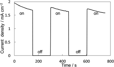
The property of H2O2 production on the BiVO4/WO3 photoanode is known to be highly excellent, and we also confirmed that the FE(H2O2) was around 90% initially on our BiVO4/WO3 photoanode in KHCO3 aqueous solution.19,29,32 Finally, the combination of the Ni10/KBHNO3 cathode with the BiVO4/WO3 photoanode was investigated in the one-compartment cell without any membrane between electrodes in 2.0 M KHCO3 aqueous solution under the solar simulator AM 1.5G (1 SUN). Fig. 8 shows the current–time dependence under simulated solar light irradiation in the two-electrode system without an applied bias potential. The current was not observed between electrodes in the dark condition. When the simulated solar light was irradiated to the photoanode, a photocurrent of >1.75 mA cm−2 was observed initially, and the photocurrent was maintained at around 1.5 mA cm−2. This photocurrent value was in agreement with that in the I–E curve at 0 V of the potential (Fig. S12†). The average FE(H2O2) from both electrodes was calculated to be 168% in total at passed charge after 0.5C using eqn (5), and the production rate of H2O2 was estimated to be 0.92 μmol min−1 cm−2. The values of the apparent solar-to-chemical energy conversion efficiency for the H2O2 production (STCH2O2) were estimated to be 1.75% without applying an external bias, using eqn (8). This value is, to the best of our knowledge, the highest among all the reported values for H2O2 production systems using simulated solar light (Table S3†). We successfully achieved highly efficient H2O2 production by only using electrolytes, oxygen, and simulated solar light, without using external electricity, a membrane, and a noble metal.
Conclusion
We have successfully prepared a highly active non-noble-metal electrocatalyst for H2O2 production from O2 in 2.0 M KHCO3 aqueous solution using an in situ preparation process. The small particles (10–40 nm) of Ni carbonate prepared by immersion of Ni nitrate in a KHCO3 solution are remarkably effective on the HNO3 pretreated KB electrode. The highest values of the FE(H2O2) and Jap(H2O2) of 82% and −9.8 mA cm−2, respectively, were obtained using a Ni10/KBHNO3 cathode at +0.5 V vs. RHE. The cathode is very stable, and the H2O2 accumulation concentration can reach 1.0 wt%. Finally, the H2O2 production on a BiVO4/WO3 photoanode and a Ni10/KBHNO3 cathode in a one-compartment photochemical cell was demonstrated without applying an external bias, and the apparent FE(H2O2) was 168% in total. The production rate of H2O2 was 0.92 μmol min−1 cm−2. The value of STCH2O2 was estimated to be 1.75% without applying an external bias. This H2O2 production system on both electrodes without external bias has great economic advantages compared to a system using a one-side electrode with bias. This one-compartment cell system without any membrane is very simple, and it will be developed using photocatalyst sheets as both cathode and anode electrodes for a large area application.19 In order to accumulate the produced H2O2 further in this system, the development of the suppression method about the H2O2 successive decomposition on the photoanode is very important.20 Moreover, the elucidation on the mechanism of the nickel carbonate basic hydrate at the atomic level by computational chemistry is also needed. They are under investigations.Conflicts of interest
There are no conflicts of interest to declare.Acknowledgements
The present work was partially supported by the International Joint Research Program for Innovative Energy Technology and JSPS KAKENHI Grant Number JP17H06436. The work at BNL was supported by the U.S. Department of Energy, Office of Science, Office of Basic Energy Sciences, Division of Chemical Sciences, Geosciences, & Bioscience, under contract DE-SC0012704.References
- Z. Qiang, J. H. Chang and C. P. Huang, Water Res., 2002, 36, 85–94 CrossRef CAS PubMed.
- J. M. Campos-Martin, G. Blanco-Brieva and J. L. G. Fierro, Angew. Chem., Int. Ed., 2006, 45, 6962–6984 CrossRef CAS PubMed.
- E. Brillas, I. Sirés and M. A. Oturan, Chem. Rev., 2009, 109, 6570–6631 CrossRef CAS PubMed.
- P. V. Nidheesh and R. Gandhimathi, Desalination, 2012, 299, 1–15 CrossRef CAS.
- M. H. M. T. Assumpcão, R. F. B. DeSouza, R. M. Reis, R. S. Rocha, J. R. Steter, P. Hammer, I. Gaubeur, M. L. Calegaro, M. R. V. Lanza and M. C. Santos, Appl. Catal., B, 2013, 142–143, 479–486 CrossRef.
- R. R. Adžić, Recent advances in the kinetics of oxygen reduction, Electrocatalysis, 1996, 1 Search PubMed.
- K. Kinoshita, Electrochemical oxygen technology, 1992, pp. 193–344 Search PubMed.
- B. Šljukić, C. E. Banks and R. G. Compton, J. Iran. Chem. Soc., 2005, 2, 1–25 CrossRef.
- F. Sandelin, P. Oinas, T. Salmi, J. Paloniemi and H. Haario, Ind. Eng. Chem. Res., 2006, 45, 986–992 CrossRef CAS.
- J. K. Edwards, E. Ntainjua, A. F. Carley, A. A. Herzing, C. J. Kiely and G. J. Hutchings, Angew. Chem., Int. Ed., 2009, 48, 8512–8515 CrossRef CAS PubMed.
- S. J. Freakley, Q. He, J. H. Harrhy, L. Lu, D. A. Crole, D. J. Morgan, E. N. Ntainjua, J. K. Edwards, A. F. Carley, A. Y. Borisevich, C. J. Kiely and G. J. Hutchings, Science, 2016, 351, 965–968 CrossRef CAS PubMed.
- Y. Nomura, T. Ishihara, Y. Hata, K. Kitawaki, K. Kaneko and H. Matsumoto, ChemSusChem, 2008, 1(7), 619–621 CrossRef CAS PubMed.
- F. Li, Q. Shao, M. Hu, Y. Chen and X. Huang, ACS Catal., 2018, 8, 3418–3423 CrossRef CAS.
- I. Yamanaka, T. Onizawa, S. Takenaka and K. Otsuka, Angew. Chem., Int. Ed., 2003, 42, 3653–3655 CrossRef CAS PubMed.
- I. Yamanaka and T. Murayama, Angew. Chem., Int. Ed., 2008, 47, 1900–1902 CrossRef CAS PubMed.
- T. Iwasaki, Y. Masuda, H. Ogihara and I. Yamanaka, Electrocatalysis, 2018, 9(2), 236–242 CrossRef CAS.
- W. T. Li, A. Bonakdarpour, E. Gyenge and D. P. Wilkinson, J. Appl. Electrochem., 2018, 48, 985–993 CrossRef CAS.
- C. Xia, Y. Xia, P. Zhu, L. Fan and H. Wang, Science, 2019, 366(6462), 226–232 CrossRef CAS PubMed.
- K. Fuku, Y. Miyase, Y. Miseki, T. Funaki, T. Gunji and K. Sayama, Chem.–Asian J., 2017, 12, 1111–1119 CrossRef CAS PubMed.
- Y. Miyase, S. Takasugi, S. Iguchi, Y. Miseki, T. Funaki, T. Gunji, K. Sasaki, E. Fujita and K. Sayama, Sustainable Energy Fuels, 2018, 2, 1621–1629 RSC.
- T. H. Jeon, H. Kim, H. Kim and W. Choi, Energy Environ. Sci., 2020, 13, 1730–1742 RSC.
- X. Shi, Y. Zhang, S. Siahrostami and X. L. Zheng, Adv. Energy Mater., 2018, 8, 1801158 CrossRef.
- Y. Liu, X. Quan, X. Fan, H. Wang and S. Chen, Angew. Chem., Int. Ed., 2015, 54, 6837–6841 CrossRef CAS PubMed.
- C. Zhao, B. Li and Q. Zhang, J. Energy Chem., 2019, 34, 10–11 CrossRef.
- Z. Chen, S. Chen, S. Siahrostami, P. Chakthranont, C. Hahn, D. Nordlund, S. Dimosthenis, J. K. Nørskov, Z. Bao and T. F. Jaramillo, React. Chem. Eng., 2017, 2, 239–245 RSC.
- R. A. Sidik, A. B. Anderson, N. P. Subramanian, S. P. Kumaraguru and B. N. Popov, J. Phys. Chem. B, 2006, 110, 1787–1793 CrossRef CAS PubMed.
- Y. H. Lee, F. Li, K. -H. Chang, C. C. Hu and T. Ohsaka, Appl. Catal., B, 2012, 126, 208–214 CrossRef CAS.
- K. Zhao, Y. Su, X. Quan, Y. Liu, S. Chen and H. Yu, J. Catal., 2018, 357, 118–126 CrossRef.
- F. Yu, M. Zhou and X. Yu, Electrochim. Acta, 2015, 163, 182–189 CrossRef CAS.
- S. Fukuzumi and Y. Lee, Chem. Eur. J, 2018, 24, 5016–5031 CrossRef CAS PubMed.
- K. Ueno and H. Misawa, NPG Asia Mater., 2013, 5, e61 CrossRef CAS.
- K. Fuku, Y. Miyase, Y. Miseki, T. Gunji and K. Sayama, RSC Adv., 2017, 7, 47619–47623 RSC.
- X. Shi, S. Siahrostami, G. Li, Y. Zhang, P. Chakthranont, F. Studt, T. Jaramillo, X. L. Zheng and J. Norskov, Nat. Commun., 2017, 8, 701 CrossRef PubMed.
- J. Liu, Y. Zou, B. Jin, K. Zhang and J. H. Park, ACS Energy Lett., 2019, 4, 3018–3027 CrossRef CAS.
- K. Zhang, J. Liu, L. Wang, B. Jin, X. Yang, S. Zhang and J. H. Park, J. Am. Chem. Soc., 2020, 142, 8641–8648 CrossRef CAS PubMed.
- Y. Xue, Y. Wang, Z. Pan and K. Sayama, Angew. Chem., Int. Ed., 2021, 60 DOI:10.1002/anie.202011215.
- J. H. Kim, J. Jang, Y. H. Jo, F. F. Abdi, Y. H. Lee, R. v. d. Krol and J. S. Lee, Nat. Commun., 2016, 13380 CrossRef CAS PubMed.
- Z. Lu, G. Chen, S. Siahrostami, Z. Chen, K. Liu, J. Xie, L. Liao, T. Wu, D. Lin, Y. Liu, T. F. Jaramillo, J. K. Nørskov and Y. Cui, Nat. Catal., 2018, 1, 156–162 CrossRef CAS.
- Z. Chen, S. Chen, S. Siahrostami, P. Chakthranont, C. Hahn, D. Nordlund, S. Dimosthenis, J. K. Nørskov, Z. Bao and T. F. Jaramillo, React. Chem. Eng., 2017, 2, 239–245 RSC.
- N. Jia, Y. Liu, L. Wang, P. Chen, X. Chen, Z. An and Y. Chen, ACS Sustainable Chem. Eng., 2020, 8, 2883–2891 CrossRef CAS.
- W. Zhou, X. Meng, J. Gao and A. N. Alshawabkeh, Chemosphere, 2019, 225, 588–607 CrossRef CAS PubMed.
- J. Lee, G. Su Park, H. Il Lee, S. T. Kim, R. Cao, M. Liu and J. Cho, Nano Lett., 2011, 11, 5362–5366 CrossRef CAS PubMed.
- J. Li, N. Zhou, J. Song, L. Fu, J. Yan, Y. Tang and H. Wang, ACS Sustainable Chem. Eng., 2018, 6, 413–421 CrossRef CAS.
- T. Kinumoto, J. Nakamura, K. Kikuchi and Z. Ogumi, Tanso, 2010, 244, 133–136 Search PubMed.
- K. Fuku and K. Sayama, Chem. Commun., 2016, 52, 5406–5409 RSC.
- D. D. Wagman, W. H. Evans, V. B. Parker, I. Halow, S. M. Bailey and R. H. Schumm, Tables for the First Thirty-Four Elements in the Standard Order of Arrangement, U. S. Government Printing Office, 1968 Search PubMed.
- S. Maeno, Tanso, 2006, 222, 140–146 CrossRef CAS.
- R. Grauer, Solubility Products of M(II)-Carbonates, PSI Bericht Nr. 99-04, 1999 Search PubMed.
- A. Moraes, M. H. M. T. Assumpção, F. C. Simões, V. S. Antonin, M. R. V. Lanza, P. Hammer and M. C. Santos, Electrocatalysis, 2016, 7, 60–69 CrossRef CAS.
- I. Yamanaka and T. Murayama, Angew. Chem., Int. Ed., 2008, 47, 1900–1902 CrossRef CAS PubMed.
- R. Haerle, E. Riedo, A. Pasquarello and A. Baldereschi, Phys. Rev. B: Condens. Matter Mater. Phys., 2001, 65, 045101 CrossRef.
- J. C. Lascovich, R. Giorgi and S. Scaglione, Appl. Surf. Sci., 1991, 47, 17–21 CrossRef CAS.
- R. Pandiyan, N. Delegan, A. Dirany, P. Drogui and M. A. El Khakani, Carbon, 2015, 94, 988–995 CrossRef CAS.
Footnote |
| † Electronic supplementary information (ESI) available. See DOI: 10.1039/d1ra01045j |
| This journal is © The Royal Society of Chemistry 2021 |

