 Open Access Article
Research progress in transition metal chalcogenide based anodes for K-ion hybrid capacitor applications: a mini-review
Muhammad Sajjad
 ab,
Fang Cheng
ab and
Wen Lu
 *ab
*ab
aInstitute of Energy Storage Technologies, Yunnan University, Kunming 650091, P. R. China. E-mail: sajjadfisica@gmail.com; wenlu@ynu.edu.cn
bCollege of Chemical Sciences and Engineering, Yunnan University, Kunming 650091, P. R. China
First published on 22nd July 2021
Abstract
Metal ion capacitors have gained a lot of interest as a new kind of capacitor-battery hybrid energy storage system because of their high power density while maintaining energy density and a long lifetime. Potassium ion hybrid capacitors (PIHCs) have been suggested as possible alternatives to lithium-ion/sodium-ion capacitors because of the plentiful potassium supplies, and their lower standard electrode potential and low cost. However, due to the large radius of the potassium ion, PIHCs also face unsatisfactory reaction kinetics, low energy density, and short lifespan. Recently, transition metal chalcogenide (TMC)-based materials with distinctive structures and fascinating characteristics have been considered an emerging candidate for PIHCs, owing to their unique physical and chemical properties. This mini-review mainly focuses on the recent research progress on TMC-based materials for the PIHC applications summarized. Finally, the existing challenges and perspectives are given to improve further and construct advanced TMC-based electrode materials.
1. Introduction
Lithium-ion batteries (LIBs) and supercapacitors (SCs) are currently successfully meeting the needs of commercial appliances such as handheld devices and electric cars. They are outperforming other energy storage systems due to their ability to provide high energy and high capacity, respectively. The key drawbacks of LIBs are their low power density and poor cycling efficiency (within 4000 cycles).1 An SC is a type of capacitor that can store a significant amount of energy per unit mass or volume, usually 10 to 100 times more than electrolytic capacitors. It is favoured over batteries because of its quicker and easier charging as well as faster charge delivery. SCs, on the other hand, have advantages in terms of power density, cycling lifespan (typically more than 100![[thin space (1/6-em)]](https://www.rsc.org/images/entities/char_2009.gif) 000 cycles), and protection, but their energy density (only 1/10 that of LIBs) restricts them.2,3 SCs cross the difference between batteries and traditional dielectric capacitors (cell voltage, specific power, and operating cost); the latter are considered to be ideal for rapid storage/release power systems,4 with power distribution and absorption of 196 kW kg−1 (10–100 times the energy density of electrolytic capacitors) in just a few seconds.5–7 It is typically advantageous to provide a high energy density, and long cycle life for practical applications in automotive power storage systems and grid energy storage systems.8–19
000 cycles), and protection, but their energy density (only 1/10 that of LIBs) restricts them.2,3 SCs cross the difference between batteries and traditional dielectric capacitors (cell voltage, specific power, and operating cost); the latter are considered to be ideal for rapid storage/release power systems,4 with power distribution and absorption of 196 kW kg−1 (10–100 times the energy density of electrolytic capacitors) in just a few seconds.5–7 It is typically advantageous to provide a high energy density, and long cycle life for practical applications in automotive power storage systems and grid energy storage systems.8–19
A hybrid-ion capacitor (HIC) is a rapidly evolving technology that incorporates batteries' and SCs' best features to produce massive energy densities at high rates over a long period. According to previous studies, these HICs can supply energy between 60 and 200 W h kg−1 (considering the mass of active materials), which is superior to a traditional SC, and their primary strength ranges between 200 and 20![[thin space (1/6-em)]](https://www.rsc.org/images/entities/char_2009.gif) 000 W kg−1, which is considerably higher than that of batteries.20,21 In comparison to Li (0.0017%), sodium (Na, 2.6%) and potassium (K, 2.1%) are plentiful in the earth's crust, rendering them promising substitutes to encourage batteries.22,23 Furthermore, both K and Na belong to the same group after Li in the periodic table, displaying similar physicochemical properties. Consequently, research into Na+/K+ storage technology is gaining momentum, paving the way to commercialize successful renewable energy storage systems.24 K+ storage devices are highlighted because they have a higher operating voltage and more excellent ionic conductivity in electrolytes than Na-ion storage devices. The K/K+ redox pair, for example, has a potential of 2.93 V (vs. standard hydrogen electrode (SHE)), which is lower than that of Na/Na+ (2.71) and quite similar to that of Li/Li+ (3.3 V vs. SHE), maintaining the functional feasibility of high energy density and high operating potential of K+ centered energy storage systems.21,25,26 Furthermore, because of the weaker Lewis acidity, K+ allows rapid transportation in the propylene carbonate electrolyte, resulting in a smaller Stokes radius (3.6). Simultaneously, Li+ and Na+ have Stokes radius values of 4.8 and 4.6, respectively.27–29 With all these fascinating benefits, designing high-energy electrode materials (both anode and cathode) that guarantee overall energy values and good structural stability for long cycling performance is a significant challenge.
000 W kg−1, which is considerably higher than that of batteries.20,21 In comparison to Li (0.0017%), sodium (Na, 2.6%) and potassium (K, 2.1%) are plentiful in the earth's crust, rendering them promising substitutes to encourage batteries.22,23 Furthermore, both K and Na belong to the same group after Li in the periodic table, displaying similar physicochemical properties. Consequently, research into Na+/K+ storage technology is gaining momentum, paving the way to commercialize successful renewable energy storage systems.24 K+ storage devices are highlighted because they have a higher operating voltage and more excellent ionic conductivity in electrolytes than Na-ion storage devices. The K/K+ redox pair, for example, has a potential of 2.93 V (vs. standard hydrogen electrode (SHE)), which is lower than that of Na/Na+ (2.71) and quite similar to that of Li/Li+ (3.3 V vs. SHE), maintaining the functional feasibility of high energy density and high operating potential of K+ centered energy storage systems.21,25,26 Furthermore, because of the weaker Lewis acidity, K+ allows rapid transportation in the propylene carbonate electrolyte, resulting in a smaller Stokes radius (3.6). Simultaneously, Li+ and Na+ have Stokes radius values of 4.8 and 4.6, respectively.27–29 With all these fascinating benefits, designing high-energy electrode materials (both anode and cathode) that guarantee overall energy values and good structural stability for long cycling performance is a significant challenge.
The comparatively plentiful reserves and low cost of potassium, potassium-ion hybrid capacitor (PIHCs) have recently emerged as a potential next-generation energy storage solution among the candidates.30,31 The developmental history of PIHC is illustrated in Scheme 1a and b. Since 2015, there has been an increase in potassium ion batteries' research papers (Scheme 1c). Since potassium does not shape Al–K intermetallic compounds thermodynamically, far less costly Al foil may be used as an anode current collector for KIBs. K has a lower standard electrode potential (−2.936 V vs. K+/K) than Na (−2.714 V vs. Na+/Na), which may contribute to a larger voltage window and better energy capacity than sodium-ion batteries (Scheme 1d). Due to the lower Lewis acidity of K+, it can shape smaller solvated ions (3.6) than Li+ (4.8) and Na+ (4.6). KIBs have a strong conductivity and a fast ion diffusion rate in the propylene carbonate (PC) solvent. Furthermore, unlike sodium-ion batteries, graphite can be used as an anode material for KIBs by creating the intercalation compound KC8, a theoretical power of 279 mA h g−1.31 Another significant benefit of K ion batteries over sodium-ion batteries is that the K+ intercalation capacity is 0.2 V vs. K+/K for other negative materials, resulting in fewer potassium metal plating and essentially preventing dendrite forming while charging in KIBs.24,28 For hard carbon, the sodiation power in NIB is 0.05 V vs. Na+/Na, while in KIB, it is 0.2 V vs. K+/K. Since potassium ions have a high ionic radius (1.38), significant volume expansion of electrode materials, predominantly negative electrodes, during the charge and discharge phase results in a limited lifetime for most KIBs (usually 500 cycles) and a low power density. The technology for storing potassium ions as energy is also in its infancy.32–35
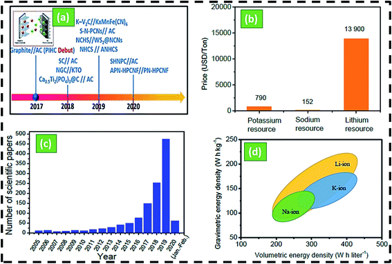 | ||
| Scheme 1 (a) The history and development of PIHCs, (b) comparison of the price of Na/Li/K,1,9,22 (c) number of publications according to the web of science with the topic of ‘potassium-ion batteries’’ from 2005 to 2020, (d) volumetric and gravimetric density of Na/Li/K-ion batteries.36,37 | ||
2. Transition metal chalcogenides nanomaterials for PIHCs
Massive volume shifts and pulverization occur in alloying metals, resulting in unexceptionally fast power decay within 200 cycles. The use of sylvite compounds in metalorganic composites reveals additional challenges to overcome, such as time-consuming planning, restricted performance, volatility, complicated K+ ion insertion/extraction reactions, and poor reliability. Due to extreme side reactions between radicals and K+ ions, insufficient active sites, and low electric/ionic conductivity, organic polymers typically have low initial coulombic efficiencies (CEs), restricted reversible capacities, and weak rate capabilities.In contrast to oxides and phosphides, transition metal chalcogenides (TMCs) have gained a lot of attention from researchers in recent years because of their broad theoretical specific power, limited volume shifts, and higher electrical conductivity, high surface area, and multiple oxidation states.38,39 These properties enable them to store significant energy via an electrical double layer. The synergistic effects between TMDs and other materials in hybrid electrode designs and hybrid configurations (e.g., PIHCs) meet the demand for high energy density requirements of modern electronic devices. In recent years, TMCs have been used as advanced hybrid electrochemical energy storage systems to solve the problems of power density and cycle life of LIBs, and low energy density of SCs,40,41 and the schematic is shown in Fig. 2. These TMCs consist of a battery-type anode (electrochemical intercalation or conversion) and a capacitor-type cathode (physical adsorption) in an electrolyte containing metal ions. They include many of the features of LIBs and SCs.29 TMC-based materials have a variety of special charge storage properties in PIHCs.42,43 The ion diffusion duration is limited since TMC-based materials have a high particular surface area, resulting in multiple exposed active areas. Secon d, TMC-based materials have quick ion transport through 2D channels that can be easily expanded and contracted. Third, materials based on TMC have excellent electrical conductivity, increasing electrode dynamics and cycle stability. Fourth, intercalation or surface redox pseudo-capacitance can be achieved using TMC-based materials. Finally, structures dependent on TMC have exceptional stability and mechanical ability. These remarkable properties suggest that metal chalcogenides-base materials can be used as cutting-edge active electrode materials in PIHCs.44–46
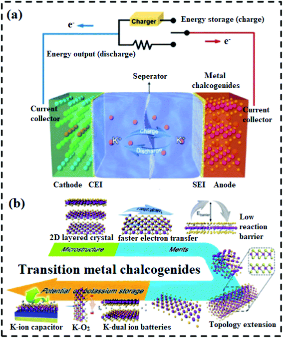
Due to the integration of two energy storage mechanisms in one device, TMCs show several preponderances, including (1) higher battery capacity and energy density than SCs, (2) higher power density than LIBs, (3) broad operating temperature range from −25 to 80 °C, and (4) self-discharge properties lower than SCs.47,48 Most metal chalcogenides have a two-dimensional (2D) layered structure and low reaction energy barriers for the handling of alkali metal ions. Because of the simplicity of topological expansion, several techniques may be used to build various morphologies of metal chalcogenides of the same crystal structure, extending the material's future applications. The TMCs, in particular, aren't only for K-ion batteries; they're “shining stars,” with applications in K dual-ion batteries, KO2 batteries, PIHCs, and other energy storage and conversion areas, as seen in Fig. 1b.49–52 This study progress study addresses essential technological advancements and dominated challenges confronting existing TMC-based PIHCs. Meanwhile, some previous TMCs-based nanostructures and nanocomposites that have been specially engineered or prepared are used to illustrate the critical alteration strategies. In the final section of the review paper, the recent progress in TMC-based materials is highlighted.
In this mini-review, we summarize the most recent endeavors towards developing high-performance PIHCs using TMD-based electrodes. Finally, we share our insights into the present challenges and possible future research directions, hoping to provide some inspirations for the design and fabrication of high-performance metal chalcogenide-based anode materials for PIHCs.
3. Potassium-ion hybrid capacitors (PIHCs)
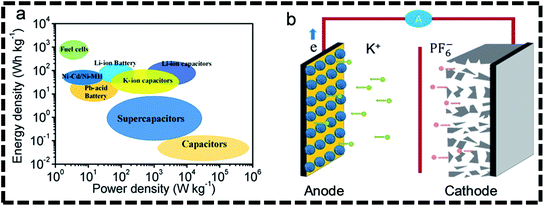
The first step toward high-performance K+-based energy storage technologies is to use host materials with superior potassium storage capacity and structural integrity to withstand repeated K+ ion injection and extraction processes.53,54 The goal mentioned above indicates that designing effective anode materials with the desirable features of high specific capacities, excellent cycling stabilities, and rapid diffusion/reaction kinetics is urgently needed to advance current PIHCs toward practical applications for PIHCs, the most representative K+-based rechargeable energy storage device.55–57 PIHCs have been regarded as possible alternatives to lithium-ion/sodium-ion capacitors because of their plentiful potassium supplies, lower standard electrode potential, and low expense.29,42,58–60 Fig. 1a illustrates how PIHCs correspond to other energy storage systems in energy density and power density diagrams.60 Research on potassium ion hybrid capacitors has seldom been recorded because of the severe kinetics mismatch between the negative and positive electrodes. The study goes into the basics of how a potassium ion capacitor works and new advancements in electrode formulations for dual-carbon and non-dual-carbon PIHCs. The electrolyte chemistry, binders, and electrode/electrolyte interface of PIHCs were also discussed. Finally, future problems and prospects for potassium ion capacitor production are discussed.4. Energy storage mechanism in PHICs
The developmental history of PIHCs is schematically presented in Fig. 1b. In 2017, Le Comte et al.42 published a groundbreaking paper on a potassium ion hybrid capacitor made up of a graphite battery-style anode and an AC electric double-layer capacitor (EDLC) type positive electrode with an Al foil current collector for both electrodes in a 0.8 mol L−1 KPF6/acetonitrile electrolyte. At the pouch cell size, superior electrochemical efficiency can be obtained, with cycling performance of up to 55![[thin space (1/6-em)]](https://www.rsc.org/images/entities/char_2009.gif) 000 cycles at a high current density of 100C/100D (corresponding to a discharge period of 30 s). With a discharge rate of up to 300C in rigid 18
000 cycles at a high current density of 100C/100D (corresponding to a discharge period of 30 s). With a discharge rate of up to 300C in rigid 18![[thin space (1/6-em)]](https://www.rsc.org/images/entities/char_2009.gif) 650 cells, corresponding to a discharge period of 12 s and an applied current of 21 A, the hybrid ion capacitor also has outstanding rate efficiency. The results reveal that the system has twice the energy density of a standard SC. The specific energy of 12 W h kg−1 can be obtained under optimal conditions by combining all of the device's components, including all electrodes collector, binder, conductive carbon, electrolyte, and separator. Since the prototypes and their excellent electrochemical efficiency, PIHCs have been studied by a few classes. The distinction between dual-carbon and nondual-carbon PIHCs is when the anode is constructed of carbon content.
650 cells, corresponding to a discharge period of 12 s and an applied current of 21 A, the hybrid ion capacitor also has outstanding rate efficiency. The results reveal that the system has twice the energy density of a standard SC. The specific energy of 12 W h kg−1 can be obtained under optimal conditions by combining all of the device's components, including all electrodes collector, binder, conductive carbon, electrolyte, and separator. Since the prototypes and their excellent electrochemical efficiency, PIHCs have been studied by a few classes. The distinction between dual-carbon and nondual-carbon PIHCs is when the anode is constructed of carbon content.
An ion insertion style negative electrode, a positive capacitor electrode with current collectors and an electrolyte (e.g., 0.8 m KPF6/EC![[thin space (1/6-em)]](https://www.rsc.org/images/entities/char_2009.gif) :
:![[thin space (1/6-em)]](https://www.rsc.org/images/entities/char_2009.gif) DEC) make up a potassium ion capacitor. Using the KPF6 electrolyte as an example, during charging, K+ from the electrolyte is injected into the negative electrode content. Simultaneously, the electrolyte's anion (PF6−) is adsorbed on the positive electrode's back. A double layer of electricity is created. K+ is liberated from the negative electrode content and returned to the electrolyte during discharge. Anions are emitted from the positive electrode surface when the electric double layer developed between the active carbon cathode and electrolyte interface dissociates. Electrons transfer from the negative electrode to the positive electrode through the external circuit (Fig. 1b).42,61 During the charge/discharge process, the battery-type anode retains a constant potential and is linked to the Faraday reaction, regulated by diffusion. The capacitor-type positive electrode exhibits a linear relationship between voltage and charge/discharge time during the charge/discharge phase and is similar to the non-Faraday reaction. During the charge/discharge operation, the battery-type anode retains a constant potential and is linked to the Faraday reaction, regulated by diffusion. According to eqn (1), the energy density of the PIHIC is proportional to the sum of squared voltage and capacitance62
DEC) make up a potassium ion capacitor. Using the KPF6 electrolyte as an example, during charging, K+ from the electrolyte is injected into the negative electrode content. Simultaneously, the electrolyte's anion (PF6−) is adsorbed on the positive electrode's back. A double layer of electricity is created. K+ is liberated from the negative electrode content and returned to the electrolyte during discharge. Anions are emitted from the positive electrode surface when the electric double layer developed between the active carbon cathode and electrolyte interface dissociates. Electrons transfer from the negative electrode to the positive electrode through the external circuit (Fig. 1b).42,61 During the charge/discharge process, the battery-type anode retains a constant potential and is linked to the Faraday reaction, regulated by diffusion. The capacitor-type positive electrode exhibits a linear relationship between voltage and charge/discharge time during the charge/discharge phase and is similar to the non-Faraday reaction. During the charge/discharge operation, the battery-type anode retains a constant potential and is linked to the Faraday reaction, regulated by diffusion. According to eqn (1), the energy density of the PIHIC is proportional to the sum of squared voltage and capacitance62
 | (1) |
The power density can be calculated according to eqn (2).7,63
 | (2) |
Besides, the mass ratio between battery-type and capacitor-type electrodes has a significant impact on the cycling life of PIHC. For hybrid capacitors, although one electrode acts as a battery electrode with different anode and cathode peaks, the cyclic voltammograms (CV) and galvanostatic charge/discharge curves of the entire device may also show more capacitor-like activity with noticeable deviation from ideal capacitive characteristics. In the case of a supercapacitor, the charge balance would be as follows: q+ = q−. Assume that the capacitance properties of a hybrid capacitor are ideal. In the electrode materials involving a different reaction mechanism, the applied current will split into the capacity of the individual electrodes. The charge balance between the two electrodes is necessary to achieve higher energy density in a hybrid capacitor configuration.64
| Qanode = Qcathode | (3) |
The total charge stored in each electrode is determined by the specific capacitance (Celectrode), the mass of the electrode (m), and the potential window (ΔE) of each electrode.
| Qelectrode = Celectrode × m × ΔE | (4) |
For asymmetrical PIHCs, the charge should be balanced.65 Therefore, the mass ratio between two electrodes can be calculated by the following eqn (5)65
 | (5) |
5. Transition metal chalcogenides (TMCs) based composite electrodes for PIHCs
The basic structure and operating theory of “rocking-chair” PIBs are depicted schematically in Fig. 2a. Because of their excellent physicochemical properties and strong theoretical ability, two-dimensional (2D) transition metal chalcogenides have drawn growing research attention for energy storage devices. TMCs have higher electrical conductivity, mechanical performance, and thermal stability than metal oxides, making them a promising candidate for HCs anode. Unfortunately, the conversion reaction's broad volume expansion induces rapid output degradation, stopping them from becoming suitable anodes for PIHCs. Furthermore, there are high hopes for maximizing the pseudo-capacitance benefits from the charge storage process to improve slow intercalation/deintercalation Na+/K+ kinetics in transition metal dichalcogenides. Designing nanomaterials is thought to be a good way to shorten the electron and ion diffusion pathways while still exposing more active areas, resulting in better rate efficiency. Despite this, metal dichalcogenides' low intrinsic conductivity induces extreme polarization effects and slow electron utilization. In the charge/discharge phase for metal dichalcogenides, coupling with carbon materials will speed up electron transfer, thus reducing volume transition. Metal chalcogenides are “shining stars,” with potential uses in K dual-ion batteries, K–O2 batteries, PIHC, and other energy storage and conversion areas, as seen in Fig. 2b.Because of its high power density and low cost, PIHCs technology has many promises for large-scale energy devices. However, it's still constrained by the slow diffusion method and inadequate K+ ion storage in the electrodes. Transition metal dichalcogenides with high power, a suitable voltage platform, and stability have emerged as a critical factor as a promising anode for PIHCs functional applications in recent years. In this regard, further research into suitable metal dichalcogenides with new approaches and structures that provide excellent pseudocapacitive conduct and apparent electrochemical kinetics is needed to realize realistic PIHCs devices with reasonable efficiency. As a superior anode material for PIHCs, Yi and colleagues created nitrogen-doped MoSe2/graphene (N-MoSe2/G) composites with good pseudocapacitive K+ ion storage.66 To make diatomite@N-MoSe2/G, diatomite templates were combined with graphite oxide, sodium molybdate, and Se powder, then hydrothermally processed and annealed. The 3D biomorphic N-MoSe2/G with large pore structures was obtained (Fig. 3a).66 The SEM and TEM photos demonstrate that the diatomite-derived N-MoSe2/G composites maintain a significant number of spherical voids, resulting in a 3D porous N-MoSe2/G structure (Fig. 3b and c). The PIHC unit, which used N-MoSe2/G as an anode and bioderived activated carbon (AC) as a cathode, provided a high energy production of 119 W h kg−1 and a high power density of 7212 W kg−1, as well as a long lifetime of 3000 cycles at 1.0 A g−1 (Fig. 3d). The unique hierarchical 3D nanoarchitecture contributes to improved electrode/electrolyte interfacial connectivity, fast ion/electron transport, reduced volume transition, and enriched active sites, resulting in a noticeable pseudocapacitive effect.
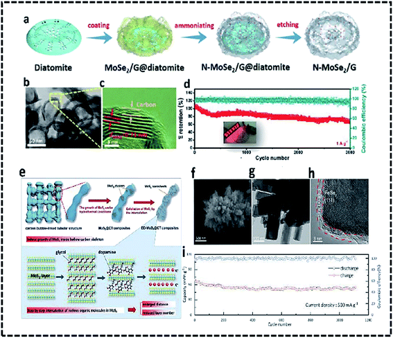 | ||
| Fig. 3 Schematic diagram of the synthetic process (a) and TEM photos (b and c) of N-MoSe2/G as an anode for PIHCs. (d) The long-term cyclic output of the N-MoSe2/G/AC PIHC system, (e) schematic diagram of the ED-MoS2@CT synthesis method,67 (f) FeSe2/N–C SEM graphic, (g) TEM image, and (h) HRTEM image.68 (i) The cycling stability of the PIHC device. | ||
Ge J. et al.68 generated ED-MoS2@CT hybrids by self-loading and anchoring well-distributed MoS2 nanosheets on hollow tubular carbon skeletons (Fig. 3e). The self-loading active materials within hollow structures were accomplished, utilizing MoS2@CT composites extracted from well-dispersed anionic groups anchored on the inner surface of HTCSs. The intercalation of ethylene glycol (EG) and dopamine (DA) hydrochloride in a step-by-step manner regulates the number of layers and interlayer spacing of MoS2. This unique MoS2@CT with the accessible and interconnecting area widened layer spacing and spacious “roads” and “houses” for fast ion/electron diffusion, and the transition will effectively alleviate mechanical strain and provide spacious “roads” and “houses” for rapid ion/electron diffusion and transition. Consequently, the ED-MoS2@CT/PC PIHC system has a strong energy/power density and good cycling stability. N-doping carbon-coated FeSe2 clusters were suggested as the anode for PIHCs by Ge and colleagues. FeSe2/N–C has a 3D structure with micro rods assembly and a diameter of about 100 nm and a carbon sheet with a thickness of about 3 nm, as seen in SEM and TEM pictures (Fig. 3f–h). With its unusual 3D nanostructures and carbon coating, the FeSe2/N–C effectively shortens the electron transport road, enhances electron conductivity, provides rich active sites, and reduces volume expansion. The PIHC achieved a high energy density of 230 W h kg−1, a strength density of 920 W kg−1, and excellent cycling endurance over 1100 cycles at 500 mA g−1, thanks to the above merits (Fig. 3i). Sheet-like MoSe2/carbon nanofibers produced by a simple electrospinning and selenization process were also investigated as anodes for PIHCs.69 The composite has outstanding performance in PIHCs, including high capacity and stability, due to the structural stability of one-dimensional nanofibers and the extended interlayer spacing of MoSe2. A sheet-on-sheet nanostructure was developed by multilayer tungsten sulfide (WS2) nanosheets anchored on nitrogen-doped carbon nanosheets metal-chelate-assisted method followed by a sulfidation procedure. During sodium/potassium ion intercalation/extraction, the composite anodes with sheet-on-sheet architecture boost electron transport, ion migration, and volume expansion of WS2, and the interface between the two nanosheets will improve pseudocapacitive charge recovery. Furthermore, the nitrogen-doped carbon hollow nanospheres cathode, which was made up of vertically aligned ultrathin carbon nanosheets, had a wide specific area and pores for anion adsorption (Fig. 4a and b).70 The nitrogen factor was uniformly distributed in the hollow carbon nanospheres according to EDX mapping (Fig. 4c). The fabricated PIHCs will produce a high energy density of 134.7 W h kg−1 at a power density of 117.5 W kg−1 due to unique characteristics and improved anode and cathode compatibility. The high energy of 103.4 W h kg−1 can also be reached at a high 235 W kg−1. Meanwhile, the mounted PIHC has shown good cycling reliability over 500 cycles, with 78% power retention at 500 mA g−1 (Fig. 4d). Ten processes of the WS2 composite anode and carbon nanospheres cathode were presented at scan rates of 0.1 and 1 mV−1, respectively, prior to assembling the hybrid complete cell to reduce irreversible power.
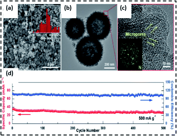 | ||
| Fig. 4 (a–c) NCHS cathode SEM and TEM characterizations, (d) cycling efficiency of the assembled NCHS/WS2@NCNS PIHCs.70 | ||
Guan's team looked at the FeS2 potassium storage mechanism.71 Fig. 5a–c indicates that when the discharge voltage decreases to 1.1 V, the peak amplitude of the FeS2 phase is significantly reduced. In contrast, a slight peak corresponding to KFeS2 appears, meaning that K+ is intercalated into FeS2 interlayers to form KxFeS2. A minor peak of the Fe process can be seen in the XRD pattern after the anode is discharged to 0.5 V. Because of the low crystallinity or the small particle size in discharge products, there were no prominent XRD peaks when the electrode was fully discharged. Peaks corresponding to KxFeS2 and K2S phases were predominantly observed after the electrode was recharged to 2.8 V, suggesting that the final charge result is KxFeS2. Surprisingly, certain potassium chalcogenides have poor reaction kinetics and also loss chemical activity when de-alloyed. Furthermore, the TEM findings show that Fe and KFeS2 are embedded in the discharge and charge materials, respectively, which agrees with the XRD results. Consequently, despite the reversibility of the deeper intercalation and conversion steps, the group concluded that the initial phase transformation between FeS2 and KxFeS2 is an irreversible potassium ion reaction, as seen in Fig. 5d. Guo's group72 was the first to investigate Sb2S3 as a PIB anode material. To understand the phase evolution of Sb2S3 during discharge/charge, they used in operando synchrotrons XRD (=0.6888), as seen in Fig. 5e. The intercalation of K+ extends the interlayer gap of Sb2S3, as evidenced by the transition to smaller diffraction angles associated with Sb2S3 above 0.7 V (Fig. 5f). Diffraction peaks attributed to Sb appeared when Sb2S3 was discharged from 0.7 to 0.5 V, suggesting the existence of transfer reactions. Peaks attributed to K2S6, K2S3, and K3Sb were produced when the voltage reached 0.1 V, but they were weak and wide due to the nano crystallinity. In situ selected area electron diffraction (SAED) verified the existence of K2S6 and Sb as intermediate products based on their polycrystalline diffraction rings, which is encouraging. Therefore, the potassiation mechanism for Sb2S3 can be summarized by eqn (6)–(8).
| Intercalation: Sb2C3 + xK+ + xe− → KxSb2S3 (x < 8) | (6) |
| Conversion: KxSb2S3 + 2xK+ + 2xe− → 2Sb + 3KxS (x < 2/3) | (7) |
| Alloying: 2Sb + 3KxS + (8 − 3x)K+ + (8 − 3x)e− → 2K3Sb + K2S3 | (8) |
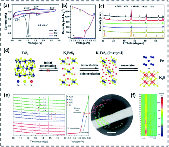 | ||
| Fig. 5 At different states of pure FeS2 anode, (a) CV curves, (b) original discharge/charge curves, and (c) ex situ X-ray diffractometry (XRD) trends, (d) a diagram depicting the potassium storage reaction process,71 (e) in situ synchrotron XRD patterns of Sb2S3 upon K insertion (left) and ex situ selected area electron diffraction (SAED) pattern (right) at 0.5 V, (f) Image plots of the (212) reflection and corresponding fitted peak.72 | ||
Apart from acknowledging undecomposed K3Sb and K2S3 in recharged materials, the phase evolution during charging was not addressed in the literature. Furthermore, Guo et al. suggested that the rapid decay in potential is due to the continuous pulverization of Sb2S3 particles induced by the massive volume shift (approximately 300%) during cycling.72 Furthermore, Xia's team looked into the potassiation/depotassiation method.71 In situ XRD, TEM, and SAED measurements were used to research the actions of SnS2. The XRD findings reveal that the conversion reaction of SnS2 starts above 1.0 V, as shown by the existence of diffraction peaks for SnS, K2S5, and K2S. Following that, further conversion and alloying reactions take place, with the prevailing power input happening between 0.01 and 0.5 V. The KSn and K2S (primary) and -Sn and K4Sn23 (secondary) were found to be the final discharge products (minor). Despite the electrode being recharged to 2.0 V, only SnS coupled with K2S (rather than SnS2) was detected. The morphology, microstructure, components, and interfacial bonding of metal-chalcogenide-based PIHCs anodes are intimately dependent on their morphology, microstructure, and components, and phase transition is very likely to be incompletely reversible, as shown by the preceding works.
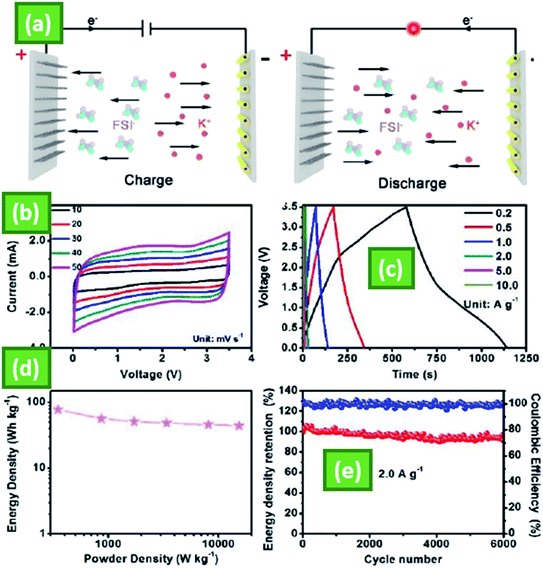
MnSe is a strongly conductive substance that often affects ion transport and storage. MnSe promotes a stable base structure, which reduces diffusive capacitive behavior and improves NiCo2O4 surface charge transfer. The output of manganese selenide (MnSe) and manganese selenide (MnSe)/nickel cobalt oxide (NiCo2O4) as electrode materials for SCs was investigated using an electrodeposition technique. The formation and configuration of the MnSe and MnSe(20)/NiCo2O4 functioning electrodes are exposed by physical characterization techniques such as X-ray diffraction, field emission scanning electron microscopy, X-ray photoelectron spectroscopy, and transmission electron microscopy. The electrochemical activity of electrodeposited MnSe and MnSe(20)/NiCo2O4 was observed and analyzed for the first time. At a current density of 0.1 A g−1, the electrodeposited MnSe and MnSe(20)/NiCo2O4 single electrodes had specific capacitances of 184.92 F g−1 and 450.75 F g−1, respectively. Furthermore, the MnSe(20)/NiCo2O4 asymmetric cell showed a particular capacitance of 45.78 F g−1 at 0.1 A g−1 and 12.46 W h kg−1 at a current density of 0.1 A g−1. The MnSe(20)/NiCo2O4 asymmetric cell demonstrated excellent long-term cycling stability over 5000 cycles, with an 86 percent capacitive retention.46 The PIHC system centered on MoS2/3Se4/3/C-HNT anode and industrial AC cathode (denoted as MoS2/3Se4/3/C-HNT/AC) is further constructed to determine its possible applications, as shown schematically in Fig. 6a. During the charging phase, K+ is intercalated into MoS2/3Se4/3/C-HNT anode, and FSI is absorbed onto the surface of the AC cathode before being extracted/desorbed and releasing the electron. In the voltage range of 0.01–3.5 V, Fig. 6b displays successive CV curves under variable scan speeds from 10 to 50 mV s−1, where minor differences from the ideal rectangular form can be shown, indicating the coexistence of faradaic and non-faradaic reactions. Because of the differing energy-storage kinetics of the anode and cathode in the hybrid capacitor, the galvanostatic charge and discharge curves at different current densities (Fig. 6c) do not show a linear relationship like a capacitor or voltage plateaus like a battery, which is compatible with the CV performance. The Ragone plot of the PIHC can be determined from the charge/discharge profiles using the combined mass of the cathode and anode with the IR decrease omitted, as seen in Fig. 6d.
At a power density of 348.1 W kg−1, an impressive energy density of 77.4 W h kg−1 was achieved. It can have an excellent energy density of 44.1 W h kg−1 even at an ultrahigh power output of 15![[thin space (1/6-em)]](https://www.rsc.org/images/entities/char_2009.gif) 414.0 W kg−1, which may be useful to practical applications requiring high power density. Importantly, the hybrid capacitor system will maintain 91.3% of its energy density after 6000 cycles with a current density of 2.0 A g−1 (Fig. 6e) and a coulombic performance of nearly 100%, showing the great ability of as-synthesized MoS2/3Se4/3/C-HNTs as anode candidates for advanced K+ dependent energy storage applications.73
414.0 W kg−1, which may be useful to practical applications requiring high power density. Importantly, the hybrid capacitor system will maintain 91.3% of its energy density after 6000 cycles with a current density of 2.0 A g−1 (Fig. 6e) and a coulombic performance of nearly 100%, showing the great ability of as-synthesized MoS2/3Se4/3/C-HNTs as anode candidates for advanced K+ dependent energy storage applications.73
6. Summary and outlook
According to previous research, TMC-based composites have a lot of capacity for potassium preservation. The reaction kinetics of TMC, which are influenced by their elements, microstructure, particle size, and hybridization, determine the depth of potassiation and depotassiation. Limiting discharge width, nanostructure engineering, containment by carbon nanophases, and ternary alloying are four standard modification techniques that can be used to overcome TMC's inherent structural instability and low electric/ionic conductivity, resulting in significant improvements in electrochemical efficiency. However, these modifications tactics pose several concerns that should be considered. Finally, we believe that future research focusing on TMC for potassium storage should pay more attention to the following points.• Build heterojunctions dependent on metal chalcogenides. This orientation tends to be unique to PIHCs dependent on metal chalcogenides. Surface/interface control, on the other side, can be an important way of guiding modifications to achieve high efficiency.
• During the synthesis of TMC-based compounds, high-temperature vulcanization occurs, thus requires high-tech equipment. This is inconvenient in terms of manufacturing and implementation. The mass development and low-cost processing of high-quality TMC-based materials must be solved before TMC-based materials can be used in PIHCs.
• Increase the amount of electrochemical activity that is regulated by capacitance. Even at high rates, most recorded TMC-based PIHCs anodes have a small capacitance-based power contribution (80%). If this aspect of power contribution can be encouraged, capacity retention can be improved at high rates. This will be particularly useful in consumer markets where quick charging is expected.
• To better understand the underlying potassium storage mechanisms, further in situ characterization is required. It is hoped that a better understanding of the process would help create new TMC-based nanostructures and provide guidance for potential material modification.
• Develop innovative potassium-based hybrid energy storage systems that incorporate the benefits of multiple energy storage technologies. This modern hybrid system is expected to make greater use of modified metal chalcogenides' superior potassium storage capacity, resulting in higher energy densities.
Current TMC for PIHCs and other potassium-based energy storage systems is expected to be overcome by advances in design, preparation, and characterization techniques, making potassium-based energy storage solutions a feasible option for daily use.
Author contributions
Dr Muhammad Sajjad: investigation, formal analysis, data curation, conceptualization, validation, writing-original draft, writing-review, and editing, Dr Fang Cheng: investigation, Prof. Wen Lu: supervision.Conflicts of interest
The authors declare that they have no known competing financial interests or personal relationships that could have influenced the work reported in this paper.Acknowledgements
This work was financially supported by The Special Significant Science and Technology Program of Yunnan Province (grant number: 2016HE001 and 2016HE002).References
- X. Zou, P. Xiong, J. Zhao, J. Hu, Z. Liu and Y. Xu, Phys. Chem. Chem. Phys., 2017, 19, 26495–26506 RSC.
- M. Yan, H. Chen, Y. Yu, H. Zhao, C. F. Li, Z. Y. Hu, P. Wu, L. Chen, H. Wang and D. Peng, Adv. Energy Mater., 2018, 8, 1801066 CrossRef.
- M. Yan, W.-P. Wang, Y.-X. Yin, L.-J. Wan and Y.-G. Guo, EnergyChem, 2019, 1, 100002 CrossRef.
- J. Huang, B. G. Sumpter and V. Meunier, Chem.–Eur. J., 2008, 14, 6614–6626 CrossRef CAS.
- M. Hashemi, M. S. Rahmanifar, M. F. El-Kady, A. Noori, M. F. Mousavi and R. B. Kaner, Nano Energy, 2018, 44, 489–498 CrossRef CAS.
- A. González, E. Goikolea, J. A. Barrena and R. Mysyk, Renewable Sustainable Energy Rev., 2016, 58, 1189–1206 CrossRef.
- M. Sajjad, J. Inorg. Organomet. Polym. Mater., 2021, 1–19 Search PubMed.
- A. S. Arico, P. Bruce, B. Scrosati, J.-M. Tarascon and W. Van Schalkwijk, Nature Materials, 2011, 148–159 Search PubMed.
- B. Dunn, H. Kamath and J.-M. Tarascon, Science, 2011, 334, 928–935 CrossRef CAS PubMed.
- J. Kim and A. Manthiram, Nature, 1997, 390, 265–267 CrossRef CAS.
- P. Poizot, S. Laruelle, S. Grugeon, L. Dupont and J. Tarascon, Nature, 2000, 407, 496–499 CrossRef CAS PubMed.
- S. J. Lee, Nat. Nanotechnol., 2010, 5, 531 CrossRef CAS PubMed.
- D. Zhao, R. Zhao, S. Dong, X. Miao, Z. Zhang, C. Wang and L. Yin, Energy Environ. Sci., 2019, 12, 2422–2432 RSC.
- T. Liu, J. P. Vivek, E. W. Zhao, J. Lei, N. Garcia-Araez and C. P. Grey, Chem. Rev., 2020, 120, 6558–6625 CrossRef CAS.
- K. J. Griffith, K. M. Wiaderek, G. Cibin, L. E. Marbella and C. P. Grey, Nature, 2018, 559, 556–563 CrossRef CAS PubMed.
- S. Chu, Y. Cui and N. Liu, Nat. Mater., 2017, 16, 16–22 CrossRef PubMed.
- A. González, E. Goikolea, J. A. Barrena and R. Mysyk, Renewable Sustainable Energy Rev., 2016, 58, 1189–1206 CrossRef.
- A. Jagadale, X. Zhou, R. Xiong, D. P. Dubal, J. Xu and S. Yang, Energy Storage Materials, 2019, 19, 314–329 CrossRef.
- M. Ma, Y. Yao, Y. Wu and Y. Yu, Advanced Fiber Materials, 2020, 1–24 Search PubMed.
- A. Eftekhari, Z. Jian and X. Ji, ACS Appl. Mater. Interfaces, 2017, 9, 4404–4419 CrossRef CAS PubMed.
- X. Wu, D. P. Leonard and X. Ji, Chem. Mater., 2017, 29, 5031–5042 CrossRef CAS.
- T. Hosaka, K. Kubota, A. S. Hameed and S. Komaba, Chem. Rev., 2020, 120, 6358–6466 CrossRef CAS PubMed.
- D. Li, Q. Sun, Y. Zhang, L. Chen, Z. Wang, Z. Liang, P. Si and L. Ci, ChemSusChem, 2019, 12, 2689–2700 CrossRef CAS PubMed.
- B. Ji, F. Zhang, X. Song and Y. Tang, Adv. Mater., 2017, 29, 1700519 CrossRef PubMed.
- L. Fan, R. Ma, Q. Zhang, X. Jia and B. Lu, Angew. Chem., Int. Ed., 2019, 58, 10500–10505 CrossRef CAS PubMed.
- K. Share, A. P. Cohn, R. Carter, B. Rogers and C. L. Pint, ACS Nano, 2016, 10, 9738–9744 CrossRef CAS.
- R. Rajagopalan, Y. Tang, X. Ji, C. Jia and H. Wang, Adv. Funct. Mater., 2020, 30, 1909486 CrossRef CAS.
- X. Zhang, D. Yang, X. Rui, Y. Yu and S. Huang, Curr. Opin. Electrochem., 2019, 18, 24–30 CrossRef CAS.
- S. Komaba, T. Hasegawa, M. Dahbi and K. Kubota, Electrochem. Commun., 2015, 60, 172–175 CrossRef CAS.
- L. Jiang, Y. Lu, C. Zhao, L. Liu, J. Zhang, Q. Zhang, X. Shen, J. Zhao, X. Yu and H. Li, Nat. Energy, 2019, 4, 495–503 CrossRef CAS.
- J. C. Pramudita, D. Sehrawat, D. Goonetilleke and N. Sharma, Adv. Energy Mater., 2017, 7, 1602911 CrossRef.
- C. D. Wessells, S. V. Peddada, R. A. Huggins and Y. Cui, Nano Lett., 2011, 11, 5421–5425 CrossRef CAS PubMed.
- H. Huang, R. Xu, Y. Feng, S. Zeng, Y. Jiang, H. Wang, W. Luo and Y. Yu, Adv. Mater., 2020, 32, 1904320 CrossRef CAS PubMed.
- K. Song, C. Liu, L. Mi, S. Chou, W. Chen and C. Shen, Small, 2019, 1903194 Search PubMed.
- L. Zhou, Z. Cao, W. Wahyudi, J. Zhang, J.-Y. Hwang, Y. Cheng, L. Wang, L. Cavallo, T. Anthopoulos and Y.-K. Sun, ACS Energy Lett., 2020, 5, 766–776 CrossRef CAS.
- W. Zhang, Y. Liu and Z. Guo, Sci. Adv., 2019, 5, eaav7412 CrossRef CAS PubMed.
- M. Liu, L. Chang, Z. Le, J. Jiang, J. Li, H. Wang, C. Zhao, T. Xu, P. Nie and L. Wang, ChemSusChem, 2020, 13, 5837–5862 CrossRef CAS PubMed.
- S. Chong, L. Sun, C. Shu, S. Guo, Y. Liu, W. A. Wang and H. K. Liu, Nano Energy, 2019, 63, 103868 CrossRef CAS.
- C. Chen, Y. Yang, X. Tang, R. Qiu, S. Wang, G. Cao and M. Zhang, Small, 2019, 15, 1804740 CrossRef PubMed.
- V. Aravindan, J. Gnanaraj, Y.-S. Lee and S. Madhavi, Chem. Rev., 2014, 114, 11619–11635 CrossRef CAS PubMed.
- Y. Zhang, J. Jiang, Y. An, L. Wu, H. Dou, J. Zhang, Y. Zhang, S. Wu, X. Zhang and M. Dong, ChemSusChem, 2020, 651–658 Search PubMed.
- A. Le Comte, Y. Reynier, C. Vincens, C. Leys and P. Azaïs, J. Power Sources, 2017, 363, 34–43 CrossRef CAS.
- L. Zhou, M. Zhang, Y. Wang, Y. Zhu, L. Fu, X. Liu, Y. Wu and W. Huang, Electrochim. Acta, 2017, 232, 106–113 CrossRef CAS.
- Z. Hai and S. Zhuiykov, Adv. Mater. Interfaces, 2018, 5, 1701385 CrossRef.
- Y.-W. Lee, B.-S. Kim, J. Hong, H. Choi, H.-S. Jang, B. Hou, S. Pak, J. Lee, S.-H. Lee and S. M. Morris, Nano Energy, 2017, 37, 15–23 CrossRef CAS.
- V. Raman, D. Chinnadurai, R. Rajmohan, V. T. Chebrolu, V. Rajangam and H.-J. Kim, New J. Chem., 2019, 43, 12630–12640 RSC.
- L. Jin, C. Shen, A. Shellikeri, Q. Wu, J. Zheng, P. Andrei, J.-G. Zhang and J. P. Zheng, Energy Environ. Sci., 2020, 13, 2341–2362 RSC.
- H. Wang, C. Zhu, D. Chao, Q. Yan and H. J. Fan, Adv. Mater., 2017, 29, 1702093 CrossRef.
- A. Vasileff, Y. Zheng and S. Z. Qiao, Adv. Energy Mater., 2017, 7, 1700759 CrossRef.
- C. Sun, Q. Dong, J. Yang, Z. Dai, J. Lin, P. Chen, W. Huang and X. Dong, Nano Res., 2016, 9, 2234–2243 CrossRef CAS.
- L. Yang, W. Zhou, J. Lu, D. Hou, Y. Ke, G. Li, Z. Tang, X. Kang and S. Chen, Nano Energy, 2016, 22, 490–498 CrossRef CAS.
- Y. Qiao, P. Yuan, Y. Hu, J. Zhang, S. Mu, J. Zhou, H. Li, H. Xia, J. He and Q. Xu, Adv. Mater., 2018, 30, 1804504 CrossRef PubMed.
- Y. Wu, H. B. Huang, Y. Feng, Z. S. Wu and Y. Yu, Adv. Mater., 2019, 31, 1901414 CrossRef CAS PubMed.
- S. Yao, J. Cui, J. Huang, J. Q. Huang, W. G. Chong, L. Qin, Y. W. Mai and J. K. Kim, Adv. Energy Mater., 2018, 8, 1702267 CrossRef.
- Y. Qian, S. Jiang, Y. Li, Z. Yi, J. Zhou, T. Li, Y. Han, Y. Wang, J. Tian and N. Lin, Adv. Energy Mater., 2019, 9, 1901676 CrossRef.
- D. Qiu, J. Guan, M. Li, C. Kang, J. Wei, Y. Li, Z. Xie, F. Wang and R. Yang, Adv. Funct. Mater., 2019, 29, 1903496 CrossRef.
- Z. Li, Y. Dong, J. Feng, T. Xu, H. Ren, C. Gao, Y. Li, M. Cheng, W. Wu and M. Wu, ACS Nano, 2019, 13, 9227–9236 CrossRef CAS PubMed.
- Z. Xu, M. Wu, Z. Chen, C. Chen, J. Yang, T. Feng, E. Paek and D. Mitlin, Adv. Sci., 2019, 6, 1802272 CrossRef PubMed.
- J. Chen, B. Yang, B. Liu, J. Lang and X. Yan, Curr. Opin. Electrochem., 2019, 18, 1–8 CrossRef.
- B. Yang, J. Chen, L. Liu, P. Ma, B. Liu, J. Lang, Y. Tang and X. Yan, Energy Storage Materials, 2019, 23, 522–529 CrossRef.
- Y. Luo, L. Liu, K. Lei, J. Shi, G. Xu, F. Li and J. Chen, Chem. Sci., 2019, 10, 2048–2052 RSC.
- M. Sajjad, R. Tao, K. Kang, S. Luo and L. Qiu, ACS Appl. Energy Mater., 2021, 4, 828–838 CrossRef CAS.
- H. Yuan, L. Kong, T. Li and Q. Zhang, Chin. Chem. Lett., 2017, 28, 2180–2194 CrossRef CAS.
- M. Sajjad, Y. Khan and W. Lu, J. Energy Storage, 2021, 35, 102336 CrossRef.
- M. Sajjad and Y. Khan, CrystEngComm, 2021, 23(15), 2869–2879 RSC.
- Y. Yi, Z. Sun, C. Li, Z. Tian, C. Lu, Y. Shao, J. Li, J. Sun and Z. Liu, Adv. Funct. Mater., 2020, 30, 1903878 CrossRef CAS.
- Y. Cui, W. Liu, W. Feng, Y. Zhang, Y. Du, S. Liu, H. Wang, M. Chen and J. Zhou, Adv. Funct. Mater., 2020, 30, 1908755 CrossRef CAS.
- J. Ge, B. Wang, J. Wang, Q. Zhang and B. Lu, Adv. Energy Mater., 2020, 10, 1903277 CrossRef CAS.
- Q. Shen, P. Jiang, H. He, C. Chen, Y. Liu and M. Zhang, Nanoscale, 2019, 11, 13511–13520 RSC.
- Y. Li, Y. Yang, P. Zhou, T. Gao, Z. Xu, S. Lin, H. Chen, J. Zhou and S. Guo, Matter, 2019, 1, 893–910 CrossRef.
- Y. Zhao, J. Zhu, S. J. H. Ong, Q. Yao, X. Shi, K. Hou, Z. J. Xu and L. Guan, Adv. Energy Mater., 2018, 8, 1802565 CrossRef.
- Y. Liu, Z. Tai, J. Zhang, W. K. Pang, Q. Zhang, H. Feng, K. Konstantinov, Z. Guo and H. K. Liu, Nat. Commun., 2018, 9, 1–10 CrossRef PubMed.
- J. Gao, G. Wang, Y. Liu, J. Li, B. Peng, S. Jiao, S. Zeng and G. Zhang, J. Mater. Chem. A, 2020, 8, 13946–13954 RSC.
| This journal is © The Royal Society of Chemistry 2021 |


