 Open Access Article
Self-supported Cu3P nanowire electrode as an efficient electrocatalyst for the oxygen evolution reaction†
Xin Zhoua,
Xiaoliang Zhou *a,
Limin Liu*a,
Hanyu Chena,
Xingguo Hua,
Jiaqi Qiana,
Di Huanga,
Bo Zhangb and
Junlei Tang*a
aCollege of Chemistry and Chemical Engineering, Southwest Petroleum University, Chengdu, 610500, PR China. E-mail: xlzhou_swpu@sina.com
bHydrogen Energy Division, Dong Fang Boiler Group Co., Ltd., Chengdu, 611731, PR China
First published on 21st October 2021
Abstract
Hydrogen is an ideal energy carrier due to its abundant reserves and high energy density. Electrolyzing water is one of the carbon free technologies for hydrogen production, which is limited by the sluggish kinetics of the half reaction of the anode – the oxygen evolution reaction (OER). In this study, a self-supported Cu3P nanowire (Cu3P NWs/CF) electrode is prepared by electrodeposition of a Cu(OH)2 nanowire precursor on conductive Cu foam (Cu(OH)2 NWs/CF) with a subsequent phosphating procedure under a N2 atmosphere. When used as an OER working electrode in 1.0 M KOH solution at room temperature, Cu3P NWs/CF exhibits excellent catalytic performance with an overpotential of 327 mV that delivers a current density of 20 mA cm−2. Notably, it can run stably for 22 h at a current density of 20 mA cm−2 without obvious performance degradation. This highly efficient and stable OER catalytic performance is mainly attributed to the unique nanostructure and stable electrode construction. Interestingly, this synthesis strategy has been proved to be feasible to prepare large-area working electrodes (e.g. 40 cm−2) with unique nanowire structure. Therefore, this work has provided a good paradigm for the mass fabrication of self-supporting non-noble metal OER catalysts and effectively promoted the reaction kinetics of the anode of the electrolyzing water reaction.
Introduction
Increasing attention to new energy and environmental issues has promoted extensive research on energy storage and conversion technologies.1,2 Water splitting driven by electricity has been considered to be a promising method to generate sustainable hydrogen.3,4 The oxygen evolution reaction (OER) is the anode half reaction of the electrochemical water splitting reaction, which is a slow kinetic process involving four electron–proton transfer and coupling.5–7 Therefore, OER is critical to the overall energy consumption and efficiency of the electrolyzing water reaction, thus designing OER electrocatalysts with high catalytic activity and stability is highly required. Recent studies have shown that noble metal based catalysts (such as RuO2 and IrO2) have good electrocatalytic activity for OER.8–10 However, their large-scale application is greatly compromised by their low reserves and high cost. Therefore, it is highly imperative to explore non-precious metal based OER electrocatalysts with high catalytic activity and stability.Recently, transition metal phosphides (TMPs) have attracted great interest in electrocatalytic OER owing to the low cost, good electrical conductivity, and high catalytic activity.11–13 Many kinds of TMPs, such as Co2P,14 CoP,15 Ni2P,16 and Fe2P17 were synthesized and proved to be excellent and durable OER electrocatalysts. However, most of these catalysts are powder catalysts and cannot be used directly as OER working electrode, which need to be coated on current collector with the aid of binder. The binder will cover part of electrocatalytic active sites and not conducive to the stability of the working electrode.18 Recently, the electrocatalysts with unique nanostructures grown directly on various conductive substrates have been proved to be a promising strategy for improving the catalytic activity and stability for OER working electrode.19,20 For example, Qiao and co-workers reported the preparation of Co3O4–carbon porous nanowire arrays on Cu foil by oxidizing a Co-based metal organic framework and used as an electrocatalyst for OER, which can generate a stable current density of 10.0 mA cm−2 with an overpotential of 290 mV in alkaline electrolyte.21 Jiang and co-workers reported the synthesis of CoP films on Cu foil via an electrodeposition method, which can achieved a current density of 10 mA cm−2 with an overpotential of 345 mV in alkaline media.22 However, previous studies have mainly focused on the preparation of small area membrane catalysts in the laboratory, such as usually less than 5 cm−2. For a water splitting device, a large-area of working electrode with efficient, inexpensive, and stable catalysts is highly required.23 Compared with other transition metals based catalysts such as Fe, Co, and Ni, Cu based catalysts have more advantages in price and reserves. Although the OER activity of Cu based catalysts is lower than that of other transition metal based catalysts, it can still be used as a substitute for noble metal catalysts.24,25 Although Cu3P has been reported as OER catalysts with excellent catalytic activity in alkaline electrolyte, the preparation of large-area Cu3P on Cu foam substrate has not been reported.26,27
In this regard, we had prepared Cu3P nanowires on Cu foam via a simple two-step method. Firstly, Cu(OH)2 NWs/CF was obtained through in situ electrochemical anodic oxidation, in which the Cu foam served as both current collector and copper source. And then Cu(OH)2 NWs/CF was converted to Cu3P/NWs after a phosphating process. The as-prepared Cu3P NWs/CF electrode exhibited high-efficient activities and outstanding stabilities for OER in alkaline media due to the unique nanostructure and the high conductivity of Cu foam. Notably, this simple two-step method has been proved to be suitable for the preparation of large-area Cu3P electrode (such as 40 cm−2), which provides a universal method for the mass fabrication of OER electrodes with high performance.
Experimental
Materials and instrumentation
All chemical reagents used in this study were all analytical graded and utilized directly without any further purification. Cu foam was purchased from Hefei Kejing Material Technology Co., Ltd. Powder X-ray diffraction (XRD) patterns were collected on a RIGAKU Ultima IV, and X-ray diffractometer was attained by Cu-Kα radiation at a scanning rate of 2° min−1. Field-emission scanning electron microscopy (FESEM) measurements were performed on Carl Zeiss Supra-55. Transmission electron microscope (TEM) measurements were conducted on FEI Talos F200s, operating at 200 kV. XPS was carried out on ESCALAB 250 instrument to determine chemical-state of the samples.Synthesis of Cu(OH)2 nanowires on Cu foam (labelled as Cu(OH)2 NWs/CF)
Firstly, a piece of Cu foam (1 cm × 2 cm) was cleaned by ultrasonication in 2 M HCl aqueous solution, ethanol, and deionized water for 5 minutes, respectively. This process is used to remove the surface oxide layer in the Cu foam. Cu(OH)2 NWs/CF was prepared by electrochemical anodic oxidation method (0.02 A cm−2 for 600 s) using a two-electrode system with Ti sheet as the counter electrode and Cu foam as the working electrode. Then, the as-prepared Cu(OH)2 NWs/CF was dried in a vacuum oven at 60 °C overnight.Synthesis of Cu3P nanowires on Cu foam (labelled as Cu3P NWs/CF)
Cu3P NWs/CF was prepared by low-temperature phosphorization of Cu(OH)2 NWs/CF. Specifically, the NaH2PO2·H2O and obtained Cu(OH)2 NWs/CF precursor were put into two different ceramic boats, and then the ceramic boat with NaH2PO2·H2O was placed on the upstream side and the ceramic boat with Cu(OH)2 NWs/CF precursor was placed at the center of tube furnace. After evacuating the air out of the tube furnace for 30 min, the samples were heated at 270 °C for 2 h at a heating rate of 2 °C min−1 under N2 atmosphere.For comparison, a pice of bare Cu foam (1 cm × 2 cm) was phosphated using the identical procedure, the as-prepared samples were labeled as Cu3P/CF in this paper.
Synthesis of RuO2 on Cu foam (labeled as RuO2/CF)
The RuO2/CF was prepared as follows: 5 mg of RuO2 was dispersed into a mixture containing 600 μL of ethanol, 340 μL of water, and 60 μL of Nafion solution (5 wt%). The solution was sonicated for 45 min to generate a homogeneous ink. Then, 100 μL of the homogeneous ink was dropped onto Cu foam (1 cm × 0.5 cm) and dried overnight at ambient conditions.Electrochemical measurements
All electrochemical tests were performed using the three-electrode system in CHI 660E electrochemical workstation. The as-prepared samples on Cu foam, Pt sheet, and Ag/AgCl were used as the working electrode, the counter electrode, and reference electrode, respectively. The linear sweep voltammetry (LSV) curves were recorded in 1.0 M KOH solution at a scan rate of 2 mV s−1 after several cyclic voltammetry (CV) cycles at a sweep rate of 100 mV s−1. The potentials were calibrated relative to hydrogen electrode (ERHE) based on the equation: ERHE = 0.197 + 0.059 × pH + EAg/AgCl. Electrochemical impedance spectroscopy (EIS) was measured at 1.6 V versus RHE in the frequency range from 100 kHz to 0.01 Hz. Chronoamperometric response (i–t) tests were evaluated to certify the stability. CV curves at different scan rates (20, 40, 60, 80, 100, and 120 mV s−1) were performed in non-faradaic potential range from 0.9 to 1.0 V (vs. RHE) to probe the electrochemical double-layer capacitance (Cdl).Results and discussion
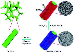
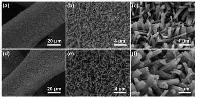
Cu foam has a large surface area, porous structure, and excellent stability and conductivity under alkaline conditions, which is beneficial to promote the OER reaction.28,29 The Cu3P nanowires on Cu foam (Cu3P NWs/CF) was synthesized by a simple two-step method, as shown in Fig. 1. The Cu(OH)2 nanowires precursor (Cu(OH)2 NWs/CF) was first obtained by electrochemical anodic oxidation on Cu foam in 1.0 M KOH solution. Powder X-ray diffraction (XRD) patterns of Cu(OH)2 NWs/CF (Fig. S1†) shows that the diffraction peaks at 16.8°, 23.8°, 33.9°, 35.7°, 38.0°, and 39.5° matched well with the (020), (021), (002), (111), (022), and (130) facets of Cu(OH)2 (PDF # 80-0656), indicating that the successful preparation of Cu(OH)2 on Cu foam. Besides, the three strong peaks at 43.1°, 50.3°, and 74.0° are attributed to the (111), (200), and (220) facets of Cu (Fig. S2†). Further, the final product of Cu3P NWs/CF was obtained by phosphating the Cu(OH)2 NWs/CF with NaH2PO2·H2O as the P source under N2 atmosphere. The colour of Cu foam changed from saffron yellow to blue, which eventually became black after low temperature phosphating at 270 °C (Fig. S3†).The morphology of Cu(OH)2 NWs/CF and Cu3P NWs/CF were observed by scanning electron microscopy (SEM). The low-magnification SEM image of Cu(OH)2 NWs/CF (Fig. 2a) shows that uniform and dense Cu(OH)2 nanowires were grown on the surface of Cu foam. From the corresponding high-magnification SEM images, Cu(OH)2 nanowires exhibited a smooth surface (Fig. 2b and c). For comparison, the SEM images of bare Cu foam are also shown in Fig. S4.† The SEM images of the Cu3P NWs/CF are shown in Fig. 2d–f. After phosphating with NaH2PO2·H2O at 270 °C under N2 atmosphere, the as-prepared Cu3P NWs/CF samples can inherit the morphology of Cu(OH)2 nanowires precursors. The dense Cu3P nanowires uniformly covered the Cu foam surface as shown in Fig. 2d. Compared with Cu(OH)2 NWs/CF, Cu3P NWs/CF samples exhibited a much rough surface (Fig. 2e and f). The scanning electron microscopy energy dispersive X-ray spectroscopy (SEM-EDX) elemental mapping images showed that Cu and P elements are uniformly distributed in Cu3P NWs/CF (Fig. S5†). For comparison, the bare Cu foam was also phosphated via a similar procedure (labelled as Cu3P/CF). The results show that Cu3P obtained by directly phosphating Cu foam does not have a unique nanostructure (Fig. S6 and S7†).
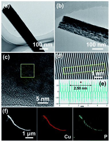
The morphology of the as-prepared Cu(OH)2 and Cu3P nanowires were further investigated by transmission electron microscopy (TEM). Fig. 3a and b displays the TEM images of Cu(OH)2 and Cu3P nanowires, suggesting the smooth surface of Cu(OH)2 nanowires became rough and porous after phosphorization. This unique morphology can not only promote the contact between electrolyte and catalyst, but also enhance the release of oxygen bubbles, leading to the enhancement of OER catalytic activity.30–33 The high-resolution TEM (HRTEM) image and the inverse fast Fourier transformation (IFFT) image of Cu3P NWs/CF exhibit that an inter-planar spacing of 0.25 nm, which is assigned to the (112) plane of Cu3P (Fig. 3c–e). The scanning TEM (STEM) image and the corresponding EDX elemental mapping images of P and Cu in Cu3P NWs/CF are shown in Fig. 3f, indicating that Cu and P elements are uniformly distributed in the whole nanowire. These results confirmed the successful synthesis of Cu3P NWs/CF on Cu foam.
The XRD patterns of Cu3P NWs/CF shows that the diffraction peaks at 36.2°, 39.3°, 41.8°, 45.1°, 46.5°, and 47.3° are indexed as the (112), (202), (211), (300), (113), and (212) planes of Cu3P (PDF # 02-1263) (Fig. 4a). In addition, the diffraction peaks at 43.3°, 50.4°, and 74.1° were attributed to (111), (200), and (220) planes of Cu. XRD measurement results show that the successful formation of Cu3P. X-ray photoelectron spectroscopy (XPS) spectrum was conducted to investigate the surface chemical composition and element valence states of the Cu3P NWs/CF. The survey scan spectrum in Fig. 4b shows the presence of Cu, P, C, and O elements, while the presence of O element may be caused by carbon contamination and air exposure.34–36 Fig. 4c shows the high-resolution XPS spectrum of Cu 2p. The peaks at 932.6 and 952.2 eV are corresponded to the Cuδ+ 2p3/2 and Cuδ+ 2p1/2 (δ is likely close to 0) in Cu3P, while the peaks at 934.6 and 954.7 eV are corresponding to the oxidized Cu2+ 2p3/2 and Cu2+ 2p1/2. The peaks at 941.1 eV, 943.9 eV, and 962.4 eV are attributed to the satellite peaks.37,38 Fig. 4d shows that the peaks of P 2p are located at 129.1 eV and 129.9, corresponding to the P 2p3/2 and P 2p1/2, respectively, which are the characteristic peaks of P in Cu3P.38,39 In addition, the peak located at 132.7 eV can be assigned to P–O bonds, which probably due to the surface oxidation of Cu3P after being exposure to air.40,41
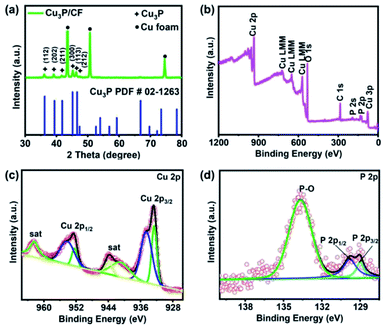 | ||
| Fig. 4 (a) XRD patterns of Cu3P NWs/CF, (b) XPS survey spectrum of Cu3P NWs/CF, high-resolution XPS spectra of (c) Cu 2p and (d) P 2p for Cu3P NWs/CF. | ||
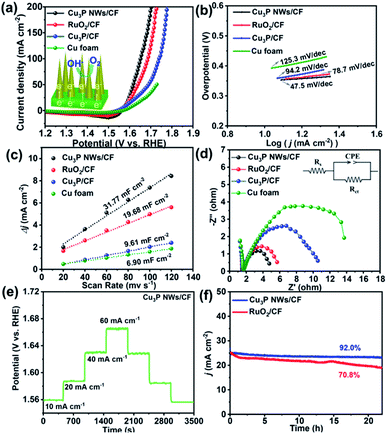
The electrocatalytic activity of Cu3P NWs/CF toward OER was investigated by a typical three-electrode system in an alkaline solution of 1.0 M KOH. For comparison, the reference samples, including Cu3P/CF, commercial RuO2/CF, and bare Cu foam were also measured in this study. In order to provide reliable electrochemical data and eliminate the effects of oxidative peaks, linear sweep voltammetry (LSV) curves of various samples were recorded from high potential to low potential with a 2 mV s−1 scan rate.25,41 As shown in Fig. 5a and S13,† the Cu3P NWs/CF electrode displayed an excellent OER catalytic performance with a low overpotential of 327 mV to reach a current density of 20 mA cm−2, which is much lower than the RuO2/CF (370 mV), Cu3P/CF (386 mV), and Cu foam (427 mV). Moreover, at a current density of 50 mA cm−2, the overpotential of Cu3P NWs/CF (352 mV) is much smaller than those of RuO2/CF (409 mV), Cu3P/CF (459 mV), and Cu foam (500 mV). To investigate the effect of Pt as counter electrode on OER activity, a graphite rod was used as counter electrode to measure LSV curve under the same conditions (Fig. S12†). The results show that LSV curve has no obvious change, indicating that Pt has a negligible effect on OER performance.42 These results suggest that the Cu3P NWs/CF can promote the OER in alkaline electrolyte. We also summarize that the OER performance of other OER electrocatalysts in previous reported articles (Table S1†). The OER performance of Cu3P NWs/CF electrode is comparable or much better than other previous reported electrocatalysts.
Furthermore, the Tafel slopes for all catalysts were investigated to have an insight into the OER kinetics of the working electrode.43,44 The Tafel slope of Cu3P NWs/CF is 74.5 mV dec−1, which is lower than those of RuO2/CF (78.7 mV dec−1), Cu3P/CF (94.2 mV dec−1), and CF (125.3 mV dec−1), implying a favorable OER kinetics for Cu3P NWs/CF (Fig. 5b). The double-layer capacitances (Cdl) were obtained based on CV curves against various scan rates (20, 40, 60 80![[thin space (1/6-em)]](https://www.rsc.org/images/entities/char_2009.gif) 100, and 120 mV s−1) (Fig. S8†).45,46 The Cu3P NWs/CF shows the larger Cdl value of 31.77 mF cm−2 than those of RuO2/CF (19.68 mF cm−2), Cu3P/CF (9.61 mF cm−2), and CF (6.90 mF cm−2) (Fig. 5c), which indicates that Cu3P NWs/CF has more electrocatalytic active sites. Electrochemical impedance spectrum (EIS) was conducted to explore the electrode kinetics.47,48 As depicted in Fig. 5d and Table S2,† Cu3P NWs/CF has a much smaller charge-transfer resistance (3.6 ohm) than RuO2/CF (4.5 ohm), Cu3P/CF (9.5 ohm), and Cu foam (14.4 ohm), implying a fast charge transfer process of Cu3P NWs/CF. The present Cu3P NWs/CF sample was firmly anchored to the Cu foam, which can effectively reduce the interface gap between the catalyst and substrate, promoting the mass and charge transfer (inset to Fig. 1a). Fig. 5e shows that the each step of multi-step chronopotentiometry curve remained unchanged for as long as 500 s with the current density of 10 mA cm−2, 20 mA cm−2, 40 mA cm−2 and 60 mA cm−2, indicating an excellent mechanical robustness and mass transportation of Cu3P NWs/CF towards OER.49,50
100, and 120 mV s−1) (Fig. S8†).45,46 The Cu3P NWs/CF shows the larger Cdl value of 31.77 mF cm−2 than those of RuO2/CF (19.68 mF cm−2), Cu3P/CF (9.61 mF cm−2), and CF (6.90 mF cm−2) (Fig. 5c), which indicates that Cu3P NWs/CF has more electrocatalytic active sites. Electrochemical impedance spectrum (EIS) was conducted to explore the electrode kinetics.47,48 As depicted in Fig. 5d and Table S2,† Cu3P NWs/CF has a much smaller charge-transfer resistance (3.6 ohm) than RuO2/CF (4.5 ohm), Cu3P/CF (9.5 ohm), and Cu foam (14.4 ohm), implying a fast charge transfer process of Cu3P NWs/CF. The present Cu3P NWs/CF sample was firmly anchored to the Cu foam, which can effectively reduce the interface gap between the catalyst and substrate, promoting the mass and charge transfer (inset to Fig. 1a). Fig. 5e shows that the each step of multi-step chronopotentiometry curve remained unchanged for as long as 500 s with the current density of 10 mA cm−2, 20 mA cm−2, 40 mA cm−2 and 60 mA cm−2, indicating an excellent mechanical robustness and mass transportation of Cu3P NWs/CF towards OER.49,50
The long-term durability of Cu3P NWs/CF and RuO2/CF were employed by chronoamperometric in 1.0 M KOH (Fig. 5f). The Cu3P NWs/CF exhibited 92% of the initial current density after 22 h sustained reaction, while RuO2/CF just showed 70.8% of the initial current density, suggesting high stability of the Cu3P NWs/CF. Meanwhile, LSV curves of Cu3P NWs/CF showed that there was no significant change after the long-term durability measurement (Fig. S9†), which also proves the good OER durability in alkaline electrolyte. To investigate the changes in structure and morphology post OER, Cu3P NWs/CF after 22 h chronoamperometry test in 1.0 M KOH solution was characterized by SEM, TEM, and XPS. SEM and TEM images show that the nanowires morphology of the Cu3P NWs/CF electrode was maintained post-OER test (Fig. S10†). Comparing to initial Cu3P NWs/CF, the XPS spectrum of Cu 2p in Cu3P NWs/CF after OER test showed two additional peaks at 933.5 eV (Cu 2p3/2) and 953.4 eV (Cu 2p1/2), which can be ascribed to the Cu2+ species (Fig. S11a†).51 This surface electrochemical oxidation process was also confirmed by the P 2p XPS spectrum (Fig. S11b†).52 Meanwhile, such an electrochemical oxidative transformation has been reported for other phosphatides-based OER electrocatalysts under alkaline electrolyte.53 Similar to the previous reported electrocatalysts,54,55 it is considered that the in situ formed phosphate layer is promoting the proton-coupled electron transfer process via unstable high valence Cu–oxo intermediate for enhancing OER activity.56–60
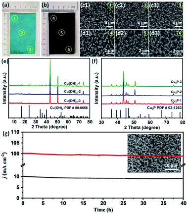
In order to further obtain the OER working electrode meeting the requirements of practical application, this simple two-step strategy was used to prepare a large-area electrode (40 cm−2). As shown in Fig. 6a, the surface of the whole Cu foam is completely covered by Cu(OH)2 after electrodeposition. After further low-temperature phosphating, a black Cu3P electrode was obtained (Fig. 6b). The edge and central regions of Cu(OH)2 and Cu3P were characterized by SEM. As shown in Fig. 6c1-3 and d1-3, both Cu(OH)2 and Cu3P show uniform nanowire morphology, which indicates that this simple two-step method can be used for large-area preparation of OER electrode. XRD patterns (Fig. 6e and f) further confirmed that the large-area of Cu(OH)2 and Cu3P nanowires were successfully synthesized. Finally, the OER catalytic activity and stability of the large-area Cu3P electrode was tested.
After about 100 CV cycles of activation, the large-area Cu3P electrode was measured by chronoamperometry for 40 hours. As shown in Fig. 6g, after 40 hours of continuous OER reaction, Cu3P electrode can operate stably at a current density of 10 mA cm−2. Even at high current density of 100 mA cm−2, no obvious attenuation of current density was observed, and the nanowire structure can still be maintained after stability measurement.
Conclusions
In summary, we demonstrate the preparation of self-supported Cu3P nanowires on Cu foam (Cu3P NWs/CF) and their application for high-efficiency electrocatalytic OER. Cu(OH)2 nanowires were in situ grown on Cu foam (Cu(OH)2 NWs/CF) by electrochemical of anodic oxidation in this paper, which is facilely converted into Cu3P nanowires with a low temperature phosphorization process under N2 atmosphere. The resulting Cu3P NWs/CF exhibits enhanced activity toward OER with a small overpotential of 327 mV at the current density of 20 mA cm−2, and good durability in alkaline medium. The unique nanowire structure, high conductivity of the electrocatalyst, and the reduced interfacial gap can effectively reduce the resistance of charge transfer as well as provide a large number of available active sites, thus enhancing the OER performance. More importantly, this simple two-step strategy is facile to fabricate large-area electrodes with uniform nanowire structure, which may promote future development of other catalysts in large-scale for water electrolysis.Conflicts of interest
There are no conflicts to declare.Acknowledgements
Funding for this work was received from the National Natural Science Foundation of China with the granted numbers of 21875056 and 22075231 and from Sichuan Science and Technology Program with the granted numbers of 2020YFSY0026 and 2021YFSY0022, for which the authors are greatly appreciative. Limin Liu gratefully acknowledges the financial support of the Fundamental Research Funds for the Central Universities (2572018BC29), and the National Natural Science Foundation of Heilongjiang Province (B2018002).Notes and references
- N.-T. Suen, S.-F. Hung, Q. Quan, N. Zhang, Y.-J. Xu and H. M. Chen, Chem. Soc. Rev., 2017, 46, 337–365 RSC.
- L. M. Gandía, R. Oroz, A. Ursúa, P. Sanchis and P. M. Diéguez, Energy Fuels, 2007, 21, 1699–1706 CrossRef.
- E. Hu, Y. Feng, J. Nai, D. Zhao, Y. Hu and X. W. D. Lou, Energy Environ. Sci., 2018, 11, 872–880 RSC.
- L. Yan, L. Cao, P. Dai, X. Gu, D. Liu, L. Li, Y. Wang and X. Zhao, Adv. Funct. Mater., 2017, 27, 1703455 CrossRef.
- H. Jiang, J. Gu, X. Zheng, M. Liu, X. Qiu, L. Wang, W. Li, Z. Chen, X. Ji and J. Li, Energy Environ. Sci., 2019, 12, 322–333 RSC.
- K. Zhu, X. Zhu and W. Yang, Angew. Chem., Int. Ed., 2019, 58, 1252–1265 CrossRef CAS PubMed.
- Y. Guo, P. Yuan, J. Zhang, H. Xia, F. Cheng, M. Zhou, J. Li, Y. Qiao, S. Mu and Q. Xu, Adv. Funct. Mater., 2018, 28, 1805641 CrossRef.
- K. A. Stoerzinger, O. Diaz-Morales, M. Kolb, R. R. Rao, R. Frydendal, L. Qiao, X. R. Wang, N. B. Halck, J. Rossmeisl and H. A. Hansen, ACS Energy Lett., 2017, 2, 876–881 CrossRef CAS.
- Y.-H. Fang and Z.-P. Liu, J. Am. Chem. Soc., 2010, 132, 18214–18222 CrossRef CAS PubMed.
- Y. Lee, J. Suntivich, K. J. May, E. E. Perry and Y. Shao-Horn, J. Phys. Chem. Lett., 2012, 3, 399–404 CrossRef CAS PubMed.
- A. Parra-Puerto, K. L. Ng, K. Fahy, A. E. Goode, M. P. Ryan and A. Kucernak, ACS Catal., 2019, 9, 11515–11529 CrossRef CAS.
- C. G. Read, J. F. Callejas, C. F. Holder and R. E. Schaak, ACS Appl. Mater. Interfaces, 2016, 8, 12798–12803 CrossRef CAS PubMed.
- K. Liu, F. Wang, P. He, T. A. Shifa, Z. Wang, Z. Cheng, X. Zhan and J. He, Adv. Energy Mater., 2018, 8, 1703290 CrossRef.
- H. Liu, J. Guan, S. Yang, Y. Yu, R. Shao, Z. Zhang, M. Dou, F. Wang and Q. Xu, Adv. Mater., 2020, 2003649 CrossRef CAS PubMed.
- Y. Lin, L. Yang, Y. Zhang, H. Jiang, Z. Xiao, C. Wu, G. Zhang, J. Jiang and L. Song, Adv. Energy Mater., 2018, 8, 1703623 CrossRef.
- L.-A. Stern, L. Feng, F. Song and X. Hu, Energy Environ. Sci., 2015, 8, 2347–2351 RSC.
- Y. Yao, N. Mahmood, L. Pan, G. Shen, R. Zhang, R. Gao, F.-e. Aleem, X. Yuan, X. Zhang and J.-J. Zou, Nanoscale, 2018, 10, 21327–21334 RSC.
- M. B. Stevens, L. J. Enman, A. S. Batchellor, M. R. Cosby, A. E. Vise, C. D. Trang and S. W. Boettcher, Chem. Mater., 2017, 29, 120–140 CrossRef CAS.
- R. Xu, R. Wu, Y. Shi, J. Zhang and B. Zhang, Nano Energy, 2016, 24, 103–110 CrossRef CAS.
- T. Wu, M. Pi, D. Zhang and S. Chen, J. Mater. Chem. A, 2016, 4, 14539–14544 RSC.
- T. Y. Ma, S. Dai, M. Jaroniec and S. Z. Qiao, J. Am. Chem. Soc., 2014, 136, 13925–13931 CrossRef CAS PubMed.
- N. Jiang, B. You, M. Sheng and Y. Sun, Angew. Chem., Int. Ed., 2015, 127, 6349–6352 CrossRef.
- J. Song, C. Wei, Z.-F. Huang, C. Liu, L. Zeng, X. Wang and Z. J. Xu, Chem. Soc. Rev., 2020, 49, 2196–2214 RSC.
- J. Du, F. Li and L. Sun, Chem. Soc. Rev., 2021, 50, 2663–2695 RSC.
- P. Zhang, L. Li, D. Nordlund, H. Chen, L. Fan, B. Zhang, X. Sheng, Q. Daniel and L. Sun, Nat. Commun., 2018, 9, 1–10 CrossRef PubMed.
- C.-C. Hou, Q.-Q. Chen, C.-J. Wang, F. Liang, Z. Lin, W.-F. Fu and Y. Chen, ACS Appl. Mater. Interfaces, 2016, 8, 23037–23048 CrossRef CAS PubMed.
- A. Han, H. Zhang, R. Yuan, H. Ji and P. Du, ACS Appl. Mater. Interfaces, 2017, 9, 2240–2248 CrossRef CAS PubMed.
- J. Xia, H. Zhao, B. Huang, L. Xu, M. Luo, J. Wang, F. Luo, Y. Du and C. H. Yan, Adv. Funct. Mater., 2020, 30, 1908367 CrossRef CAS.
- X. Zhou, W. Qi, K. Yin, N. Zhang, S. Gong, Z. Li and Y. Li, Front. Chem., 2020, 7, 900 CrossRef PubMed.
- W. Jiang, J. Chen, G. Qian, H. He, H. Zhang, X. Zhuo, F. Shen, L. Luo and S. Yin, Electrochim. Acta, 2021, 390, 138887 CrossRef CAS.
- J. Liu, G. Qian, H. Zhang, J. Chen, Y. Wang, H. He, L. Luo and S. Yin, Chem. Eng. J., 2021, 426, 131253 CrossRef CAS.
- J. Chen, Y. Wang, G. Qian, T. Yu, Z. Wang, L. Luo, F. Shen and S. Yin, Chem. Eng. J., 2021, 421, 129892 CrossRef CAS.
- G. Qian, J. Chen, T. Yu, L. Luo and S. Yin, Micro Nano Lett., 2021, 13, 1–13 CrossRef CAS PubMed.
- Y. Wang, G. Qian, Q. Xu, H. Zhang, F. Shen, L. Luo and S. Yin, Appl. Catal., B, 2021, 286, 119881 CrossRef CAS.
- F. Shen, Y. Wang, G. Qian, W. Chen, W. Jiang, L. Luo and S. Yin, Appl. Catal., B, 2020, 278, 119327 CrossRef CAS.
- Q. Wang, Z. Zhang, C. Cai, M. Wang, Z. L. Zhao, M. Li, X. Huang, S. Han, H. Zhou, Z. Feng, L. Li, J. Li, H. Xu, J. S. Francisco and M. Gu, J. Am. Chem. Soc., 2021, 143, 13605–13615 CrossRef CAS PubMed.
- J. Tian, Q. Liu, N. Cheng, A. M. Asiri and X. Sun, Angew. Chem., Int. Ed., 2014, 126, 9731–9735 CrossRef.
- H. Pfeiffer, F. Tancret and T. Brousse, Electrochim. Acta, 2005, 50, 4763–4770 CrossRef CAS.
- M. Kong, H. Song and J. Zhou, Adv. Energy Mater., 2018, 8, 1801489 CrossRef.
- J. Li, G. Wei, Y. Zhu, Y. Xi, X. Pan, Y. Ji, I. V. Zatovsky and W. Han, J. Mater. Chem. A, 2017, 5, 14828–14837 RSC.
- C. Du, L. Yang, F. Yang, G. Cheng and W. Luo, ACS Catal., 2017, 7, 4131–4137 CrossRef CAS.
- T. Wang, H. Chen, Z. Yang, J. Liang and S. Dai, J. Am. Chem. Soc., 2020, 142, 4550–4554 CrossRef CAS PubMed.
- A. Wu, Y. Xie, H. Ma, C. Tian, Y. Gu, H. Yan, X. Zhang, G. Yang and H. Fu, Nano Energy, 2018, 44, 353–363 CrossRef CAS.
- J. Chen, F. Zheng, S.-J. Zhang, A. Fisher, Y. Zhou, Z. Wang, Y. Li, B.-B. Xu, J.-T. Li and S.-G. Sun, ACS Catal., 2018, 8, 11342–11351 CrossRef CAS.
- D. Chen, J. Zhu, X. Mu, R. Cheng, W. Li, S. Liu, Z. Pu, C. Lin and S. Mu, Appl. Catal., B, 2020, 268, 118729 CrossRef CAS.
- S. L. Zhang, B. Y. Guan, X. F. Lu, S. Xi, Y. Du and X. W. Lou, Adv. Mater., 2020, 32, 2002235 CrossRef CAS PubMed.
- L. Zhang, L. Wang, Y. Wen, F. Ni, B. Zhang and H. Peng, Adv. Mater., 2020, 32, 2002297 CrossRef CAS PubMed.
- H. Zhang, A. W. Maijenburg, X. Li, S. L. Schweizer and R. B. Wehrspohn, Adv. Funct. Mater., 2020, 2003261 CrossRef CAS.
- Y. Li, Z. Wang, J. Hu, S. Li, Y. Du, X. Han and P. Xu, Adv. Funct. Mater., 2020, 1910498 CrossRef CAS.
- C. Liang, P. Zou, A. Nairan, Y. Zhang, J. Liu, K. Liu, S. Hu, F. Kang, H. J. Fan and C. Yang, Energy Environ. Sci., 2020, 13, 86–95 RSC.
- Z. Hu, Q. Liu, W. Lai, Q. Gu, L. Li, M. Chen, W. Wang, S. L. Chou, Y. Liu and S. X. Dou, Adv. Energy Mater., 2020, 10, 1903542 CrossRef CAS.
- Q. Shi, Q. Liu, Y. Ma, Z. Fang, Z. Liang, G. Shao, B. Tang, W. Yang, L. Qin and X. Fang, Adv. Energy Mater., 2020, 10, 1903854 CrossRef CAS.
- Y. Hou, X. Zhuang and X. Feng, Small Methods, 2017, 1, 1700090 CrossRef.
- J. Lu, X. Luo, T. Wu, K. Amine and L. Ma, Division of Fuel Chemistry Preprints, American Chemical Society, 2016 Search PubMed.
- J. Lu, S. Yin and P. K. Shen, Electrochem. Energy Rev., 2019, 2, 105–127 CrossRef CAS.
- J. Xu, J. Li, D. Xiong, B. Zhang, Y. Liu, K.-H. Wu, I. Amorim, W. Li and L. Liu, Chem. Sci., 2018, 9, 3470–3476 RSC.
- W. Li, D. Xiong, X. Gao and L. Liu, Chem. Commun., 2019, 55, 8744–8763 RSC.
- F. Hu, S. Zhu, S. Chen, Y. Li, L. Ma, T. Wu, Y. Zhang, C. Wang, C. Liu and X. Yang, Adv. Mater., 2017, 29, 1606570 CrossRef PubMed.
- R.-Q. Li, B.-L. Wang, T. Gao, R. Zhang, C. Xu, X. Jiang, J. Zeng, Y. Bando, P. Hu and Y. Li, Nano Energy, 2019, 58, 870–876 CrossRef CAS.
- S. Riyajuddin, S. Tarik Aziz, S. Kumar, G. D. Nessim and K. Ghosh, ChemCatChem, 2020, 12, 1394–1402 CrossRef CAS.
Footnote |
| † Electronic supplementary information (ESI) available. See DOI: 10.1039/d1ra05526g |
| This journal is © The Royal Society of Chemistry 2021 |

