 Open Access Article
Preparation and characterization of a self-suspending ultra-low density proppant
Zhifeng Luoa,
Jianbin Li *a,
Liqiang Zhaoa,
Nanlin Zhang
 *a,
Xiang Chen*a,
Weijie Miaob,
Weihua Chenc and
Chong Liangd
aState Key Laboratory of Oil and Gas Reservoir Geology and Exploitation, Southwest Petroleum University, Chengdu 610500, China. E-mail: li15884539161@163.com; Nanlin_zhang@163.com; Chen_swpu@163.com
bPetroleum Engineering Technology Institute of Southwest Petroleum Branch, SINOPEC, Deyang 618000, China
cEngineering Technology Research Institute of Southwest Oil & Gas Field Company, PetroChina, Chengdu, Chengdu 610017, China
dResearch Institute of Petroleum Exploration and Development, CNPC, Beijing 100083, China
First published on 7th October 2021
Abstract
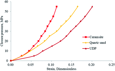
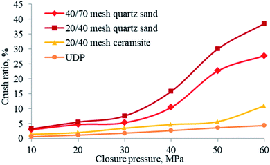
A self-suspending ultra-low density proppant (UDP) was developed based on the polymerization of the unsaturated carbon double bond. Its performance was characterized by FT-IR and SEM, and the sphericity and roundness, diameter distribution, density, mechanical properties, the conductivity of the propped fracture, and mass loss of different fluids were measured. The test results indicated that the UDP no longer contained the unsaturated carbon double bond and the polymerization took place in the raw material. The fracture surface of UDP is compact and it is not easy to produce debris after compression failure. The sphericity and roundness of UDP were above 0.9, and the high sphericity and roundness provided high conductivity. The stirring speed has a great influence on the diameter of UDP, and the UDP with different sizes could be used to prop the hydraulic fracture to different widths. The average apparent density of UDP is as low as 1.044 g cm−3, and it can be suspended in the fracturing fluid for a long time. The strain in the UDP is higher than that in the ceramsite and quartz sand, but its crushing ratio is far below theirs; therefore, the conductivity of the fracture propped by UDP was higher than that of quartz sand and ceramsite. The solubility of UDP in kerosene, reservoir water, and hydrochloric acid is below 1%, indicating that the UDP is also suitable for acid fracturing with proppant. All the experimental results proved that the self-suspending ultra-low density proppant has great potential use in hydraulic fracturing and acid fracturing.
1. Introduction
Hydraulic fracturing is often used in unconventional reservoirs to improve hydrocarbon recovery.1–3 In the process of fracturing, the proppant serves as the most important material to avoid fracture closure.4,5 Although proppants are widely used, there are two serious weaknesses: (1) with the continuous development of the deep reservoir, the proppant may break, deform, and embed under the high closure stress, resulting in the decrease of the hydraulic fracture width, which can not provide sufficient conductivity. (2) To carry high-strength proppant in fracturing treatment, it is necessary to use high-viscosity fracturing fluid, but high polymer concentration will lead to formation damage.These disadvantages of fracturing proppants mentioned above are often responsible for fracture failure, which is in the process of construction and production, pollution, injury, blockage and other reasons caused the fracture conductivity to decrease continuously until the fracture failed.6 Novel proppants have been proposed and developed to mitigate these problems. Hao et al. prepared a low-density ceramic proppant with calcined flint clay (45.6 wt% Al2O3) and solid waste coal gangue by solid-state sintering method; the low-density ceramic proppant sintered at 1400 °C had the best performance with bulk density of 1.27 g cm−3, apparent density of 2.79 g cm−3, breakage ratio of 3.27% under 35 MPa closed pressure and 8.36% under 52 MPa closed pressure.7 Kincaid et al. proposed a self-suspending proppant in which conventional proppant particles are encapsulated with a thin layer of high-molecular-weight hydrogel polymer to form a self suspending proppant (SSP); once the SSP comes into contact with water, the hydrogel layer expands spontaneously and it forms a space-filling cushion around each granule, thereby increasing the volume of the particle and decreasing the particle density resulting in the reducing of settling rate of the proppant suspension.8 Song et al. proposed a hydro-thermal reaction to form hydroxyapatite crystals on calcite-rich shale surfaces to act as proppants;9 the most obvious defect of this method is its low conductivity. Chang et al. developed an in situ proppant generated from a fracturing fluid containing chemical precursors that will set into spherical particle beads; since the fracturing fluid is solid-free, abrasion of the equipment due to the proppant is avoided.10 J. D. Wine et al. performed numerous fracture design and production simulations, conductivity tests performed at 100 °F indicate organo-metallic crosslinked fracturing fluids yield significantly more conductivity impairment than borate crosslinked fluids.11 Conductivity studies performed under in situ conditions by Penny have shown polymer loading, type of crosslinker, and breaker system dramatically affect the conductivity of a proppant pack.12 Other proppants with different functions or performances have been developed for different oil and gas reservoirs, such as the low crushing rate proppant,13 oil-wet proppant,14 expandable proppant,15 and non-spherical proppant.16
Existing proppants have addressed some problems, but the density and suspension ability do not meet the requirement of network fracturing. It is difficult to fully prop the hydraulic fracture network. With the development of the petroleum industry, oil and gas exploration aims at extraction from shallow layers to deep layers, and from low closure pressure to high and ultra-high closure pressure. The requirement of increasing the proppant strength causes a concomitant increase in proppant density, and finally causes the consequences that the proppants settle rapidly near the well.17 Therefore, it is necessary to carry out the research and development of high-strength and low-density proppants to improve the fracturing effect. In this study, we describe a self-suspending ultra-low density proppant, which may be used as a novel fracturing treatment agent.
2. Experimental section
2.1 Materials
The materials needed for UDP production are as follows:18Paraxylene (PX); acrylonitrile (AN); hydrogen peroxide (HP, ωH2O2 = 35%); ferrous sulfate (FS); 1,3,5-tri-2-propenyl-1,3,5-triazine-2,4,6(1H,3H,5H)-trione (TAIC); vinyl acetate (VA).
A typical preparation method is as follows:
(1) 50 g PX, 12 g VA and 2 g AN are added into the beaker and stirred until they are completely dissolved at room temperature (25 °C);
(2) 2 g HP solution is added to the beaker and stirred until it is fully mixed;
(3) In another beaker, take 10 g TAIC, heat it in a water bath at 40 °C, and slowly add the solution prepared in the previous step while stirring;
(4) 2 g FS is added to the solution prepared in step (3), name the mixture liquid MX, and stirred until the self-suspending spherical ultra-low density proppant (UDP) particles are formed.
2.2 Fourier transform infrared (FT-IR) measurements
The Fourier Transform Infrared (FT-IR) spectra of UDP and the liquid mixture before the generation of UDP are tested with a WQF-520A Fourier transform infrared spectrometer. The test method is as follows: drop the mixed liquid onto a piece of KBr sheet and spread it evenly on the sheet surface. The FT-IR test can be carried out using this sample. Use pure spectral KBr and UDP to prepare a mixture with the mass ratio (KBr![[thin space (1/6-em)]](https://www.rsc.org/images/entities/char_2009.gif) :
:![[thin space (1/6-em)]](https://www.rsc.org/images/entities/char_2009.gif) UDP = 50
UDP = 50![[thin space (1/6-em)]](https://www.rsc.org/images/entities/char_2009.gif) :
:![[thin space (1/6-em)]](https://www.rsc.org/images/entities/char_2009.gif) 1), mix it evenly, grind, and roll into thin slices. Their infrared spectrum is measured by a WQF-520A Fourier transform infrared spectrometer at room temperature.
1), mix it evenly, grind, and roll into thin slices. Their infrared spectrum is measured by a WQF-520A Fourier transform infrared spectrometer at room temperature.
2.3 SEM measurements
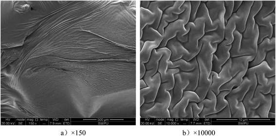
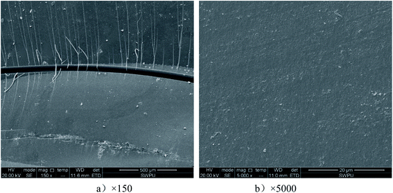
The morphology of MX was investigated by an FEI Quanta 450 ESEM (environmental scanning electron microscope). MX was frozen using liquid nitrogen. The frozen surfaces of the samples were observed with ESEM operating at an accelerating voltage of 20 kV.Besides, the morphology of UDP was investigated using the FEI Quanta 450 environmental scanning electron microscope.
2.4 Density tests of UDP
The density of UDP determines its suspension performance and its ability to be carried by the fracturing fluid. The lower the density, the easier it is to be carried by the fracturing fluid, and the easier it is to enter the far end of the fracture to improve the conductivity there. The density includes both apparent density and bulk density. The test method for apparent density is as follows:(1) Use a balance with a sensitivity of 0.0001 g to weigh the mass m1 of the dry empty density bottle;
(2) Fill the density bottle with water and weigh its mass m2;
(3) Empty the density bottle and dry it;
(4) Fill the density bottle with ethanol and weigh its mass m3;
(5) Measure out an appropriate amount of UDP. The mass is equal to m4;
(6) Pour out approximately half of the ethanol in the density bottle, and move the UDP in step (5) to the density bottle;
(7) Fill the density bottle with ethanol and rotate it along the vertical axis until all bubbles in the density bottle are discharged. If necessary, refill the bottle with ethanol, and weigh the mass m5.
The calculated equation of apparent density is:
 | (1) |
The method for measurement of bulk density is:
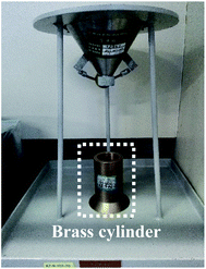
(1) Take a balance of sensitivity 0.0001 g to weigh the mass m7 of the empty brass cylinder of Q/SY-2 bulk density meter (Fig. 1);
(2) Close the outlet of the funnel with a rubber ball valve, center the brass cylinder directly below the outlet of the funnel, and pour the UDP sample into the funnel from the beaker;
(3) Open the rubber ball valve at the bottom of the funnel, pour the UDP samples into the brass cylinder from the funnel, and use a ruler to smoothen it at the edge of the cylinder, so that the sample is flush with the surface of the brass cylinder mouth;
(4) The weight of the brass cylinder and the sample in the cylinder is m8.
The bulk density is calculated using the equation:
 | (2) |
2.5 Sphericity and roundness of UDP measurements
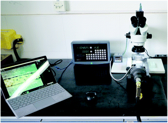
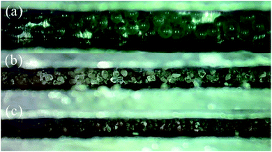
The morphology of UDP was characterized by the ICM (image collecting microscope) shown in Fig. 2. Then, process the image taken by the ICM and extract the edges of all proppant particles in the image, the roundness and sphericity are measured based on the edges. The sphericity was measured qualitatively according to the ISO 13503-2-2006 standard (Fig. 3) based on the image taken by the ICM.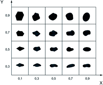 | ||
| Fig. 3 Chart for visual estimation of sphericity and roundness in ISO 13503-2-2006 (X-roundness, Y-sphericity). | ||
2.6 Diameter measurements of UDP
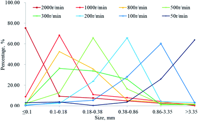
The particle size of UDP determines the width of a hydraulic fracture into which it can enter and how suitable it is for fracturing. Once the raw material ratio of UDP is determined, its diameter is only related to the stirring speed. Therefore, the particle size distribution under different stirring speeds is tested.2.7 Mechanical property test
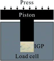
Under the high closure pressure in the hydraulic fracture, UDP may break and embed into the formation rock, resulting in a decrease in the conductivity of the propped fractures. Hence, it is necessary to test the compressive strength of UDP. The strain of the UDP under different pressures and the long-term strain under 55 MPa were tested with the experimental device shown in Fig. 4. The strains in ceramsite, quartz sand, and UDP under different pressures were compared.The test method for compressive strength is as follows:
(1) Prepare an equal amount of ceramsite, quartz sand and UDP respectively, and use the compressive strength test device shown in Fig. 4 to gradually pressurize to 55 Mpa;
(2) Measure the strain values of ceramsite, quartz sand and UDP under different stresses;
(3) Prepare equal amounts of 40/70 mesh quartz sand, 20/40 mesh quartz sand, 20/40 mesh ceramsite and UDP, and gradually pressurize them to 60 Mpa;
(4) Screening, weighing and calculating the crushing rate under different stresses;
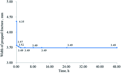
(5) Prepare a certain amount of UDP, and pressurize it stably at 55 Mpa;
(6) Measure UDP strain values at different times.
2.8 Fracture conductivity
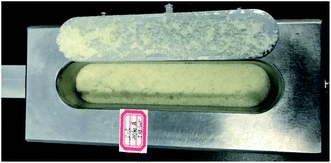
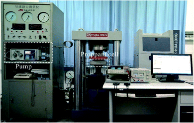
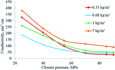
The conductivity of the propped-fracture is the key parameter in evaluating the effect of fracturing. Under high closure pressure, the conductivity and proppant concentration vary greatly, making testing imperative. According to SY/T6302-2009,19 the conductivity test steps are shown as follows:(1) The set mass of UDP, quartz sand, and ceramsite was subjected to the proppant cell (Fig. 5) of the conductivity test device (Fig. 6), respectively.
(2) The closure pressure was set to a different value, respectively.
(3) The outlet flow under each test pressure, the left and right width of the propped fracture, and the reading of the differential pressure transmitter were recorded, the fracture conductivity value was calculated using eqn (3).
 | (3) |
2.9 Mass loss rate tests in different fluids
After UDP enters the hydraulic fracture, it will be in high temperature and high-pressure fluid environment for a long time. The physical and chemical stability in the formation fluid environment directly determines the long-term fracturing effect. Therefore, it is necessary to test the mass loss of UDP in crude oil and reservoir water. To facilitate the analysis, the mass loss rate of UDP is tested with kerosene and reservoir water respectively.(1) UDP with a mass of m0 is put in the reaction kettle and diesel or reservoir water with a mass of m′ is added;
(2) The reaction kettle is sealed and placed in an electric oven, and the temperature is set to 120 °C;
(3) After 48 h, take out the reaction kettle, dry the UDP at 80 °C for 6 h, and weigh its mass m.
The mass-loss rate is calculated by:
 | (4) |
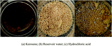
The proppant and acid may be used together in hydraulic fracturing. The proppant is used to support hydraulic fractures, and acid is used to break the fracturing fluid or remove carbonate plugs.20 Therefore, it is necessary to test the mass loss rate of UDP in the acid solution. The mass-loss rate of UDP in 20% hydrochloric acid was tested by the method mentioned above.
3. Results and discussions
3.1 FT-IR measurements
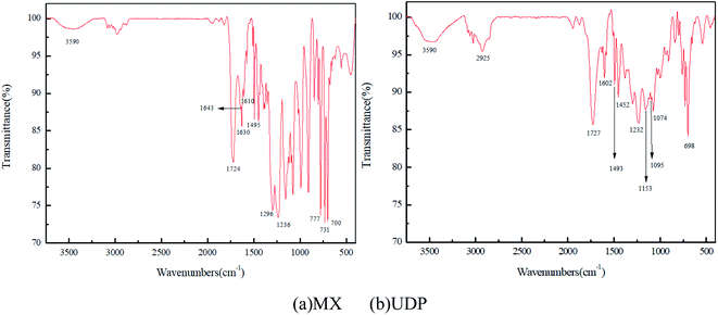
![[double bond, length as m-dash]](https://www.rsc.org/images/entities/char_e001.gif) O and C–O respectively, indicating that there are a large number of ester groups in the molecular chain; the characteristic absorption peaks of C
O and C–O respectively, indicating that there are a large number of ester groups in the molecular chain; the characteristic absorption peaks of C![[double bond, length as m-dash]](https://www.rsc.org/images/entities/char_e001.gif) C are found at 1630 cm−1 and 1643 cm−1, indicating that there are two kinds of C
C are found at 1630 cm−1 and 1643 cm−1, indicating that there are two kinds of C![[double bond, length as m-dash]](https://www.rsc.org/images/entities/char_e001.gif) C in the MX, namely, the C
C in the MX, namely, the C![[double bond, length as m-dash]](https://www.rsc.org/images/entities/char_e001.gif) C from the TAIC and the VA. There is a wide peak at approximately 3590 cm−1, which is the stretching vibration peak of –OH, and there is an obvious absorption peak at 1296 cm−1, which is the stretching vibration peak of C–O in primary alcohol.
C from the TAIC and the VA. There is a wide peak at approximately 3590 cm−1, which is the stretching vibration peak of –OH, and there is an obvious absorption peak at 1296 cm−1, which is the stretching vibration peak of C–O in primary alcohol.In Fig. 7b, there is a wide peak at approximately 3590 cm−1, which is the stretching vibration peak of –OH. The obvious characteristic absorption peaks at 1727 cm−1 and 1232 cm−1 were C![[double bond, length as m-dash]](https://www.rsc.org/images/entities/char_e001.gif) O and C–O, indicating the presence of the ester group in the molecular chain. No obvious absorption peak was found in the range of 1620–1680 cm−1, indicating that unsaturated carbon double bond was no longer contained in the UDP and the polymerization took place between TAIC and the VA.
O and C–O, indicating the presence of the ester group in the molecular chain. No obvious absorption peak was found in the range of 1620–1680 cm−1, indicating that unsaturated carbon double bond was no longer contained in the UDP and the polymerization took place between TAIC and the VA.
3.2 SEM measurements
3.3 Density of UDP
| Item | No. 1 | No. 1 | No. 1 | Average |
|---|---|---|---|---|
| Apparent density (g cm−3) | 1.044 | 1.042 | 1.045 | 1.044 |
| Bulk density (g cm−3) | 0.671 | 0.638 | 0.655 | 0.655 |
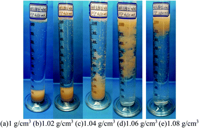
The average apparent density of UDP is approximately 1.044 g cm−3, and the bulk density is approximately 0.655 g cm−3. The bulk density of UDP is close to that of water. Fig. 10 shows the UDP suspended in KCl solutions with different densities. UDP was nearly suspended in the KCl solution with a density of 1.04 g cm−3. When the density of the KCl solution increased to 1.08 g cm−3, UDP was completely suspended in the solution. The density of the fracturing fluid is usually more than 1.1 g cm−3, so that UDP can remain in suspension and effectively improve the fracturing effect. The density of UDP is lower than the existing low-density proppant.7,22–27
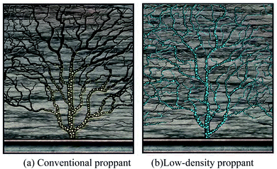 | ||
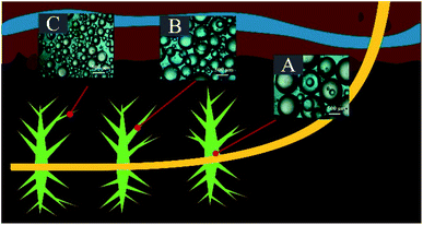
| Fig. 11 Prop effect of conventional proppant and low-density proppant.28 | ||
3.4 Sphericity and roundness of UDP
3.5 Diameter distribution
3.6 Mechanical properties
The effect of stress on the fracture width is significant.34 The width of the propped fracture decreased rapidly during the first 0.04 h. Subsequently, the decrease tended to be slow and continued to be the same for 2 hours (Fig. 18). The test results indicated that UDP exhibited long-term stability, maintained good propping performance, and a long-term high conductivity under 55 MPa closure stress. Through the analysis of fracture width, the best viscosity parameters of fracturing fluid are obtained, and the fracturing fluid is optimized.35
3.7 Fracture conductivity
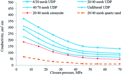
Due to the low crushing ratio and high sphericity, the conductivity of the fracture propped by UDP was higher than that of quartz sand and ceramsite (Fig. 20).
3.8 Mass loss rate in different fluids
| Item | Mass of UDP before the test, g | Mass of UDP after the test, g | Mass loss rate |
|---|---|---|---|
| Kerosene | 5 | 4.95 | 1.0% |
| Reservoir water | 5 | 4.96 | 0.8% |
| Hydrochloric acid | 5 | 4.99 | 0.2% |
3.9 Proppant embedment
After stimulating a well, the conductivity and porosity of the well will decline because of proppant embedment as well as deformation.36 Particle shapes also affect the overall mechanical behavior and embedment of proppant pack in fractures.37 Proppants appear to undergo substantial proppant pack compaction and porosity reduction due to the strong in situ confining stresses that occur underground.38 The embedment of proppants leads to the decrease of conductivity. However, the fracture conductivity test has shown that the conductivity of UDP propped fracture is higher than that of quartz sand and ceramsite under high closing stress. This shows that the UDP embedding amount is small.4. Conclusions
A self-suspending ultra-low density proppant (UDP) was developed based on the polymerization between the unsaturated carbon double bonds. Its performance was characterized by FT-IR, SEM, as well as the measurement of sphericity and roundness, diameter distribution, density, mechanical property, the conductivity of propped fracture, and mass loss in different fluids. The test results indicated that the average apparent density of UDP is as low as 1.044 g cm−3 and the low density makes it easy for the proppant to be carried to the tip of the hydraulic fracture, which ensures that the tip of the fracture is also propped and this significantly improves the fracturing effect. Besides, the sphericity and roundness, mechanical properties, and conductivity of UDP are better than that of ceramsite and quartz sand, and the acid resistance performance indicates that the UDP is also suitable for acid fracturing with the proppant. All experimental results indicate that the self-suspending ultra-low density proppant has great potential for use in hydraulic fracturing and acid fracturing.Funding sources
This work was supported by the National Natural Science Foundation of China (51974264), the Research and Innovation Fund for Graduate Student of Southwest Petroleum University (2019CXZD018).Author contributions
The manuscript was written through the contributions of all authors. All authors have given approval to the final version of the manuscript. These authors contributed equally.Conflicts of interest
The authors declare no competing financial interest.References
- Y. Hu, J. Zhao, J. Zhao, C. Zhao, Q. Wang, X. Zhao and Y. Zhang, Coiled tubing friction reduction of plug milling in long horizontal well with vibratory tool, J. Pet. Sci. Eng., 2019, 177, 452–465 CrossRef CAS
.
- P. Liu, F. Liu, C. She, L. Zhao, Z. Luo, W. Guan and N. Li, Multi-phase fracturing fluid leakoff model for fractured reservoir using extended finite element method, J. Nat. Gas Sci. Eng., 2016, 28, 548–557 CrossRef
.
- J. Zhao, Q. Wang, Y. Hu, L. Ren and C. Zhao, Numerical investigation of shut-in time on stress evolution and tight oil production, J. Pet. Sci. Eng., 2019, 179, 716–733 CrossRef CAS
.
- D. Fjaestad and I. Tomac, Experimental investigation of sand proppant particles flow and transport regimes through narrow slots, Powder Technol., 2019, 343, 495–511 CrossRef CAS
.
- N. Li, J. Li, L. Zhao, Z. Luo, P. Liu and Y. Guo, Laboratory Testing on Proppant Transport in Complex-Fracture Systems, SPE Prod. Oper., 2017, 32(4), 382–391 CAS
.
- Y. Liu, Z. Zhang, F. Gao, Y. Liu and X. Zhang, Fracture failure and its influence on well productivity in low permeability reservoir[A], 2018 IFEDC International Conference on Exploration and Development of Oil and Gas Fields[C], Xi 'an Petroleum University, Shaanxi Petroleum Institute: Xi 'an Huaxian Network Information Service Co., Ltd., 2018, p. 9 Search PubMed
.
- J. Hao, H. Hao, Y. Gao, X. Li, M. Qin and K. Wang, Effect of Sintering Temperature on Property of Low-Density Ceramic Proppant Adding Coal Gangue, Mater. Sci., 2020, 26(1), 94–98 CrossRef
.
- K. P. Kincaid, P. M. Snider, M. Herring, R. P. Mahoney and D. Soane, Self-Suspending Proppant, in SPE Hydraulic Fracturing Technology Conference, Society of Petroleum Engineers: The Woodlands, Texas, USA, 2013, pp. 1–12 Search PubMed
.
- S. Tong, C. Miller and K. Mohanty, Generation of In-Situ Proppant through Hydro-Thermal Reactions, in SPE Hydraulic Fracturing Technology Conference and Exhibition, Society of Petroleum Engineers: The Woodlands, Texas, USA, 2019, pp. 1–13 Search PubMed
.
- F. F. Chang, P. D. Berger and C. H. Lee, In-Situ Formation of Proppant and Highly Permeable Blocks for Hydraulic Fracturing, in SPE Hydraulic Fracturing Technology Conference, Society of Petroleum Engineers: The Woodlands, Texas, USA, 2015, pp. 1–11 Search PubMed
.
- J. D. Wine, M. P. DeBonis and R. L. Thomas, The Effect of Guar and HPG Crosslinked Fracturing Fluids on Well Performance: A Case Study, paper presented at the Low Permeability Reservoirs Symposium, Denver, Colorado, March 1989 Search PubMed
.
- G. S. Penny, An Evaluation of the Effects of Environmental Conditions and Fracturing Fluids Upon the Long-Term Conductivity of Proppants, paper SPE 16900 presented at the 1987, SPE Annual Technical Meeting, Dallas, TX, Sept. 27-30 Search PubMed
.
- X. Ren, Q. Hu, X. Liu, Y. Shen, C. Liu, L. Yang and H. Yang, Nanoparticles Patterned Ceramsites Showing Super-Hydrophobicity and Low Crushing Rate: The Promising Proppant for Gas and Oil Well Fracturing, J. Nanosci. Nanotechnol., 2019, 19(2), 905–911 CrossRef CAS PubMed
.
- T. Palisch, M. Chapman and J. Leasure, Novel Proppant Surface Treatment Yields Enhanced Multiphase Flow Performance and Improved Hydraulic Fracture Clean-up, in SPE Liquids-Rich Basins Conference - North America, Society of Petroleum Engineers: Midland, Texas, USA, 2015, pp. 1–11 Search PubMed
.
- L. Santos, A. Dahi Taleghani and G. Li, Expandable proppants to moderate production drop in hydraulically fractured wells, J. Nat. Gas Sci. Eng., 2018, 55, 182–190 CrossRef
.
- J. Xu, Y. Ding, L. Yang, Z. Liu, R. Gao, H. Yang and Z. Wang, Conductivity analysis of hydraulic fractures filled with nonspherical proppants in tight oil reservoir, Energy Sci. Eng., 2020, 8(1), 166–180 CrossRef CAS
.
- S. Shiozawa and M. McClure, Simulation of proppant transport with gravitational settling and fracture closure in a three-dimensional hydraulic fracturing simulator, J. Pet. Sci. Eng., 2016, 138, 298–314 CrossRef CAS
.
- Z. Luo, L. Wu, L. Zhao, N. Zhang, C. Zhou, H. Liu, P. Liu, N. Li, N. Li, J. Liu, Y. Geng, Y. Zhang and D. Ren, A production method of ultra-low density proppant based on supramolecular materials, CN 110511306A, 2019-11-29
.
- National_Energy_Board_of_China, SY/T 6302-2009 Recommended practices for evaluating short term proppant pack conductivity, Petroleum Industry Press, 2009 Search PubMed
.
- P. Karadkar, W. Suzart, A. Sabhapondit, A. Buenrostro and J. L. Jauregui, Novel High Viscus Acid System for Proppant Fracture Acidizing, in Abu Dhabi International Petroleum Exhibition & Conference, Society of Petroleum Engineers, Abu Dhabi, UAE, 2016, p. 10 Search PubMed
.
- C. Zhang, L. Zhao, D. Yu, G. Liu, Y. Pei, F. Huang and B. Liu, The evaluation on physical property and fracture conductivity of a new self-generating solid proppant, J. Pet. Sci. Eng., 2019, 177, 841–848 CrossRef CAS
.
- J. Fan, T. P. Bailey, Z. Sun, P. Zhao, C. Uher, F. Yuan and M. Zhao, Preparation and properties of ultra-low density proppants for use in hydraulic fracturing, J. Pet. Sci. Eng., 2018, 163, 100–109 CrossRef CAS
.
- X. Han, Q. Cheng, F. Bao, J. Gao, Y. Yang, T. Chen, C. Yan and R. Ma, Synthesis of Low-Density Heat-Resisting Polystyrene/Graphite Composite Microspheres Used as Water Carrying Fracturing Proppants, Polym.-Plast. Technol. Eng., 2014, 53(16), 1647–1653 CrossRef CAS
.
- G. Li, X. Chang, B. Zhu, K. Wang, Y. Zhou, Y. Wu, Y. Tian and P. Bai, Sintering mechanism of high-intensity and low-density ceramic proppants prepared by recycling of waste ceramic sands, Adv. Appl. Ceram., 2019, 118(3), 114–120 CrossRef CAS
.
- R. Ma, W. Tang, P. Hu and T. Chen, Fabrication of low-density heat-resistance polystyrene/carbon black composite microspheres used as hydraulic fracturing proppant, Mater. Express, 2019, 9(2), 150–158 CrossRef CAS
.
- X. Ma, Y. Tian, Y. Zhou, K. Wang, Y. Chai and Z. Li, Sintering temperature dependence of low-cost, low-density ceramic proppant with high breakage resistance, Mater. Lett., 2016, 180, 127–129 CrossRef CAS
.
- J. Zhao, Z. Liu and Y. Li, Preparation and characterization of low-density mullite-based ceramic proppant by a dynamic sintering method, Mater. Lett., 2015, 152, 72–75 CrossRef CAS
.
- G. Xinjun, W. Minsheng, H. Fuwei and G. Lidong, Proppants for Fracturing Fluids: New Progress Made and Direction of Future Development, Drill. Fluid Completion Fluid, 2019, 36(5), 529–541 Search PubMed
.
- K. Jackson and O. Orekha, Low Density Proppant in Slickwater Applications Improves Reservoir Contact and Fracture Complexity - A Permian Basin Case History, in SPE Liquids-Rich Basins Conference - North America, Society of Petroleum Engineers: Midland, Texas, USA, 2017, pp. 1–20 Search PubMed
.
- A. Radwan, A Multifunctional Coated Proppant: A Review of Over 30 Field Trials in Low Permeability Formations, in SPE Annual Technical Conference and Exhibition, Society of Petroleum Engineers, San Antonio, Texas, USA, 2017, pp. 1–20 Search PubMed
.
- A. Neto, F. Prata, J. Gomez, C. A. Pedroso, M. Martins and D. Silva, Ultralightweight Proppants: An Effective Approach To Address Problems in Long Horizontal Gravel Packs Offshore Brazil, SPE Drill. Completion, 2013, 27, 613–624 CrossRef
.
- P. Siddhamshetty, S. Mao, K. Wu and J. S.-I. Kwon, Multi-Size Proppant Pumping Schedule of Hydraulic Fracturing: Application to a MP-PIC Model of Unconventional Reservoir for Enhanced Gas Production, Processes, 2020, 8, 570 CrossRef CAS
.
- S. Jiang, P. Chen, M. Yan, B. Liu, H. Liu and H. Wang, Model of effective width and fracture conductivity for hydraulic fractures in tight reservoirs, Arabian J. Sci. Eng., 2020, 45, 7821–7834 CrossRef CAS
.
- A. M. Elsarawy and H. A. Nasr-El-Din, A new method to measure propped fracture width and proppant porosity in shale fractures, J. Pet. Sci. Eng., 2019, 181, 106162 CrossRef CAS
.
- S. Pahari, P. Bhandakkar, M. Akbulut and J. S. I. Kwon, Optimal pumping schedule with high-viscosity gel for uniform distribution of proppant in unconventional reservoirs, Energy, 2021, 216, 119231 CrossRef CAS
.
- A. Katende, L. O’Connell, A. Rich, J. Rutqvist and M. Radonjic, A comprehensive review of proppant embedment in shale reservoirs: Experimentation, modeling and future prospects, J. Nat. Gas Sci. Eng., 2021, 104143 CrossRef
, ISSN 1875-5100..
- N. I. Osuji, J. Zhang and M. D. Tagne, Numerical simulation on the effect of particle shape on mechanical response of proppants in horizontal fractures, Computational Particle Mechanics, 2021, 2196–4386 Search PubMed
.
- A. A. A. Alzanam, U. Ishtiaq, A. S. Muhsan and N. M. Mohamed, A Multiwalled Carbon Nanotube-Based Polyurethane Nanocomposite-Coated Sand/Proppant for Improved Mechanical Strength and Flowback Control in Hydraulic Fracturing Applications, ACS Omega, 2021, 6(32), 20768–20778 CrossRef CAS PubMed
.
| This journal is © The Royal Society of Chemistry 2021 |

