 Open Access Article
Li-doped beryllonitrene for enhanced carbon dioxide capture
Andrew Pu and
Xuan Luo†
 *
*
National Graphene Research and Development Center, Springfield, Virginia 22151, USA. E-mail: xluo@ngrd.org
First published on 23rd November 2021
Abstract
In recent years, the scientific community has given more and more attention to the issue of climate change and global warming, which is largely attributed to the massive quantity of carbon dioxide emissions. Thus, the demand for a carbon dioxide capture material is massive and continuously increasing. In this study, we perform first-principle calculations based on density functional theory to investigate the carbon dioxide capture ability of pristine and doped beryllonitrene. Our results show that carbon dioxide had an adsorption energy of −0.046 eV on pristine beryllonitrene, so it appears that beryllonitrene has extremely weak carbon dioxide adsorption ability. Pristine beryllonitrene could be effectively doped with lithium atoms, and the resulting Li-doped beryllonitrene had much stronger interactions with carbon dioxide than pristine beryllonitrene. The adsorption energy for carbon dioxide on Li-doped beryllonitrene was −0.408 eV. The adsorption of carbon dioxide on Li-doped beryllonitrene greatly changed the charge density, projected density of states, and band structure of the material, demonstrating that it was strongly adsorbed. This suggests that Li-doping is a viable way to enhance the carbon dioxide capture ability of beryllonitrene and makes it a possible candidate for an effective CO2 capture material.
1 Introduction
Climate change has been an important issue facing the world since the 20th century, and research has shown that this is largely a result of the increase in greenhouse gas emissions.1 The majority of these greenhouse gas emissions are from carbon dioxide (CO2). In 2016, CO2 accounted for about 81.6% of all manmade greenhouse gas emissions in the US.2 Global warming caused by the increase in greenhouse gas emissions has caused the arctic ice caps to melt, resulting in higher sea levels.3 Rising temperatures also increase the prevalence of droughts and heatwaves, which are both significant threats to the safety of mankind.4 Thus, the demand for a material to efficiently capture CO2 from the air has been massive. Currently, there are 3 main methods for CO2 capture: pre-combustion, post-combustion, and oxyfuel.5 When applied to the burning of fossil fuels, pre-combustion and oxyfuel CO2 capture are both performed before CO2 is actually released into the air, while post-combustion CO2 capture refers to the process of capturing CO2 from the resulting gas mixtures. Thus, post-combustion CO2 capture methods are more applicable to the issue of capturing existing greenhouse gasses from the atmosphere.6Previously, several materials and processes for post-combustion CO2 capture have been explored. Two of the most promising methods of post combustion CO2 capture are chemical absorption and adsorption.7 Amine scrubbing, which is one process used for chemical absorption CO2 capture, has been practiced since its patent in 1930.8 However, chemical absorption processes usually require large equipment, large volumes of solvent, high regeneration energy, and toxic byproducts.9 On the other hand, several adsorbents have been researched for their CO2 capture ability.7 Many chemical CO2 adsorbents have been studied, including several amine-based adsorbents, but their low CO2 capacity and high cost have reduced their viability.7 Meanwhile, several different physical adsorbents have also been explored and researched, including porous coal, carbonaceous material, zeolite, fullerenes, oxides, and MOFs.7,10 For example, Signorile et al. investigated the possibility of using Mg overexchanged zeolite Y to adsorb carbon dioxide molecules,11 and Mino et al. explored the use of titanium dioxide as well.12 Many studies have also been performed to investigate the possibility of pressure and temperature regulated CO2 capture using physical adsorbents.13,14 However, for all these adsorptive CO2 capture methods, the gaseous feed must be treated, and the gaseous mixture usually has to be cooled and dried,15 which reduces the viability. Additionally, these three-dimensional materials have a very little surface area to volume ratio, so they are very inefficient at capturing carbon dioxide molecules. Since the discovery of graphene in 2004, two-dimensional materials have also gathered lots of interest as physical CO2 adsorbents.16
Two-dimensional materials have a large surface area, atomic-thin structure, and a large surface-to-volume ratio, making them great potential candidates for CO2 capture.17 Unfortunately, previous experiments have shown that pristine graphene doesn't demonstrate particularly strong interactions with CO2.18 This has prompted other researchers to investigate the possibility of two-dimensional materials other than graphene for carbon dioxide capture. Hexagonal boron nitride has a very similar structure to graphene, but it displays greater thermal conductivity, and the nitrogens are believed to be potential active sites for carbon dioxide chemisorption.19 Jiao et al. performed density functional theory calculations to investigate this but found that pristine hexagonal boron nitride monolayers were also ineffective for carbon dioxide adsorption.19 Silicene and germanene were thought to be potential materials because, unlike graphene and boron nitride, they have a buckled hexagonal structure, which gives them greater chemical reactivity.20 Both pristine silicene and pristine germanene only demonstrated physisorption with CO2.21,22 Monolayer molybdenum disulfide (MoS2) was also investigated due to its unique triple layered buckled structure.23 Like the other two-dimensional materials, pristine MoS2 also did not display much adsorption ability for CO2, so it cannot be directly used as an efficient sorbent for CO2.24 Several other two-dimensional materials have been investigated for their CO2 capture ability, including aluminum nitride,25 zinc oxide,26 gallium nitride,27 silicon phosphide,28 silicon carbide,29 graphyne,30–32 borophene,33 and several different carbon nitrides.34–37 Most of these 2D materials are unable to strongly chemisorb CO2 while in their pristine form. However, other studies have found that dopants and defects were able to greatly increase the adsorption capabilities of many of these 2D materials. Li et al. and Chandra et al. both found that graphene's CO2 capture ability was greatly increased after nitrogen doping.38,39 Boron nitride was shown to have increased CO2 adsorption behavior after fluorine doping and boron vacancies.19,40 Silicene and Germanene both displayed much greater CO2 capture ability after Li-functionalization,20,41 and MoS2 monolayers with S vacancies also demonstrated much better adsorption ability.23 Recently, Bykov et al. discovered a new two-dimensional material known as beryllonitrene, which could be a potential CO2 capture material due to its unusual structure and variety of binding sites.42
Beryllonitrene is a monolayer form of BeN4 that was created by performing high-pressure synthesis followed by decompression on triclinic BeN4.42 Not much research has been conducted regarding its practical applications, including in the field of gas capture and gas sensing. Beryllonitrene is similar to the previously stated two-dimensional materials in that it’s structure is close to a honeycomb structure, and it has a hexagonal unit cell.43 Each unit cell consists of one beryllium atom and four nitrogen atoms, so the material is mostly composed of nitrogen.43 Like in boron nitride, these nitrogens could act as potential carbon dioxide adsorption sites.19 Beryllonitrene has been shown to be both dynamically and thermodynamically stable.42 The monolayer exhibits semimetallic behavior43 and has a large surface area, similar to other two-dimensional materials, making it a good candidate for CO2 adsorption. Due to the unique properties and lack of research for beryllonitrene, it is important to investigate the potential of beryllonitrene for CO2 capture.
In this study, we use density functional theory to calculate the adsorption of CO2 molecules onto the surface of pristine beryllonitrene and Li-doped beryllonitrene in order to determine whether they have the potential to be effectively used as a CO2 capture device.
2 Methods
2.1 Computational details
First-principle calculations using density functional theory (DFT)44,45 as implemented in the ABINIT program46–51 were performed using the generalized gradient approximation (GGA) with the Perdew–Burke–Ernzerhof (PBE) formalism as the exchange-correlation functional.52 Projector augmented-wave (PAW)53,54 pseudopotentials were selected, which were generated by ATOMPAW code.55 The electron configurations and radius cutoffs used for generating the PAW pseudopotentials are listed in Table 1.| Element | Electron configuration | rcut (bohr) |
|---|---|---|
| Beryllium (Be) | 1s2 2s2 | 1.6 |
| Nitrogen (N) | [He] 2s2 2p3 | 1.2 |
| Aluminum (Al) | [Ne] 3s2 3p1 | 1.9 |
| Phosphorus (P) | [Ne] 3s2 3p3 | 1.9 |
| Sulfur (S) | [Ne] 3s2 3p4 | 1.9 |
Convergence calculations were performed to determine appropriate converged values for the kinetic energy cutoff, k point mesh, and vacuum. The values were considered converged when the difference in total energy between two data sets was less than 1.0 × 10⁻⁴ Ha two times consecutively. During the convergence calculations, the self-consistent field (SCF) total energy calculations were considered complete when the total energy difference was less than 1.0 × 10⁻¹⁰ Ha twice. For the relaxation of the lattice parameters and atomic structure, the Broyden–Fletcher–Goldfarb–Shanno (BFGS) method56 was used. During the BFGS relaxation calculations, the SCF iteration was terminated when the total difference in forces was less than 2.0 × 10⁻⁵ Ha bohr−1 two times consecutively. The BFGS relaxation calculations were considered complete when all of the forces were less than 2.0 × 10⁻⁴ Ha bohr−1.
2.2 CO2 adsorbed on pure beryllonitrene
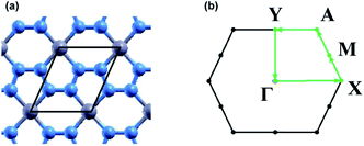
Convergence calculations were performed on a 1 × 1 unit cell of beryllonitrene, shown in Fig. 1(a), and then converged values were used for relaxation of the atomic structure. Convergence and relaxation calculations were also performed on a single carbon dioxide molecule. Calculations for the adsorption of carbon dioxide on beryllonitrene were performed using a 2 × 2 surpercell of beryllonitrene.The adsorption energy of CO2, Eads, on each material was calculated by
| Eads = Eber+CO2 − Eber − ECO2 | (1) |
2.3 CO2 adsorbed on doped beryllonitrene
Convergence and relaxation calculations were also performed for 2 × 2 supercells of doped beryllonitrene. Calculations for the adsorption of carbon dioxide on the doped beryllonitrene were also performed, and the adsorption energy was found using eqn (1).The defect formation energy, Edef, for each doped beryllonitrene monolayer is defined by
| Edef = Eber+dop − Eber − Edop | (2) |
2.4 Electronic structure
The charge transfer, Δρ(τ), involved in the adsorption of CO2 was calculated by| Δρ(τ) = ρber+CO2(τ) − ρber(τ) − ρCO2(τ) | (3) |
The band structure was calculated for each beryllonitrene monolayer and each complex using Γ, X, M, A, and Y as the high symmetry k points, as shown in Fig. 1(b). The tetrahedron method was used to plot the projected density of states (PDOS) for the different monolayers and complexes. The PDOS graphs use the 2s orbital for lithium and beryllium, as well as the 2p orbitals for carbon, nitrogen, and oxygen.
3 Results & discussion
In this study, we first optimized the structure of beryllonitrene, Li-doped beryllonitrene, and a single carbon dioxide molecule. We then calculated the adsorption energy of carbon dioxide on each of the monolayers. The carbon dioxide was considered chemisorbed when the absolute value of the adsorption energy was greater than the chemisorption threshold of −0.30 eV, which is equivalent to −0.011 Ha.10,253.1 Atomic structure
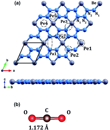
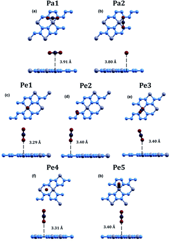
The optimized atomic structures for the materials were found using BFGS relaxation calculations, which gives the molecules free range of motion and any bonds formed are chemical bonds.56Full relaxation calculations were performed for each configuration of beryllonitrene and carbon dioxide. The relaxed values were used to perform total energy calculations for the relaxed configuration. For the first two configurations, Pa1 and Pa2, we placed the carbon dioxide molecule horizontally above the beryllonitrene such that the oxygen atoms of carbon dioxide were above the nitrogen atoms in beryllonitrene, as shown in Fig. 2(a). Position Pa1 for CO2 is above the BeN4 pentagon and parallel to the a axis. Position Pa2 for CO2 is above the Be2N4 hexagon and perpendicular to the a axis.
In the other five configurations (Pe1, Pe2, Pe3, Pe4, and Pe5), the carbon dioxide was placed perpendicular to the plane of the two-dimensional beryllonitrene, as shown in Fig. 2(a). Position Pe1 for CO2 is above a beryllium atom, Position Pe2 for CO2 is above a nitrogen atom, Position Pe3 for CO2 is above a Be–N bond, Position Pe4 for CO2 is above a Be2N4 hexagon, and Position Pe5 for CO5 is above a BeN4 pentagon.
| Position | Eads (Ha) | d (Å) | ∠O–C–O (°) |
|---|---|---|---|
| Pa1 | −0.0016 | 3.91 | 180 |
| Pa2 | −0.0017 | 3.80 | 180 |
| Pe1 | 0.0000 | 3.29 | 180 |
| Pe2 | 0.0000 | 3.40 | 180 |
| Pe3 | 0.1050 | 3.40 | 180 |
| Pe4 | 0.0851 | 3.31 | 180 |
| Pe5 | 0.0521 | 3.40 | 180 |
The relaxed atomic structure for all seven configurations is shown in Fig. 3. The adsorption energy, CO2 height, and CO2 bond angle for the configurations were calculated (Table 3). In all 7 configurations, the bond angle of carbon dioxide stayed at around 180°. The most optimal position for carbon dioxide adsorption on beryllonitrene was found to be position Pa2, which was horizontally above the beryllonitrene, 3.80 Å above the BeN4 pentagon, and perpendicular to the a axis, as shown in Fig. 3(b). This configuration has an adsorption energy of −0.0017 Ha, which is more negative than the adsorption energy for the other six configurations, but it still doesn't reach the chemisorption threshold of −0.011 Ha. For comparison, the adsorption energy for carbon dioxide on pristine boron nitride is −0.0018 Ha,19 and the adsorption energy on pristine graphene is around −0.002 Ha. This suggests that the carbon dioxide molecule is only physically adsorbed onto the surface of pristine beryllonitrene. Since the interactions between the carbon dioxide and pristine beryllonitrene are extremely weak, they may be attributed to weak London dispersion forces. All of the configurations of carbon dioxide on pristine beryllonitrene had adsorption energies smaller than −0.011 Hartree,10,25 which means that carbon dioxide cannot spontaneously chemisorb onto the beryllonitrene, and pristine beryllonitrene is not a viable adsorbent for CO2 capture.
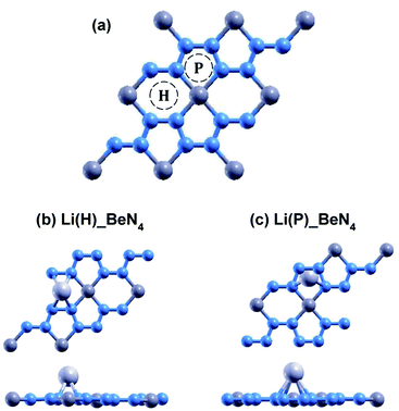
The relaxed atomic structures for each of the doped beryllonitrene supercells are shown in Fig. 4 and 5. The defect formation energy was calculated for each doped beryllonitrene monolayer (Table 4). When placed at H, all three of the dopants appeared to stay in the same spot. When placed on ste P, the dopants tended to move perpendicular to the a axis towards site H. When Al was placed on site P, the Al atom actually moved all the way to site H. The total energy for each of the dopant–beryllonitrene complexes was greater when the dopant was placed at H rather than P. Adsorption of Ca and Al on both sites resulted in positive defect formation energies, which suggests that Ca and Al atoms would prefer to form metallic clusters rather than adsorb to the surface of beryllonitrene57 at these two sites. On the other hand, Li has negative defect formation energies at both sites, so it is likely to adsorb to the surface of beryllonitrene. One possible explanation for the difference in behavior between Li and the other two metals is that they are all cations, but Li is an alkali metal with only one valence electron, so it has much greater electropositivity than Al or Ca. This means that Li is more likely to strongly bond with the electronegative nitrogen atoms in beryllonitrene. On site H, Li had a defect formation energy of −0.0192 Ha, while Li on site P had a defect formation energy of −0.0121 Ha. Both of these defect formation energies are negative and are greater in magnitude than −0.011 Ha, which is considered the chemisorption threshold,10,25 so Li is considered to be chemically adsorbed onto beryllonitrene on both of these sites, and the Li-doped beryllonitrene is considered to be stable. Since there was greater defect formation energy for Li at site 1 than at site 2, Li(H)_BeN4 is more stable than Li(P)_BeN4 (shown in Fig. 4). Since Li(H)_BeN4 was the most stable doped configuration, it was used for further calculations.
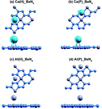 | ||
| Fig. 5 Optimized atomic structure of beryllonitrene doped with Ca at (a) H and (b) P, as well as beryllonitrene doped with Al at (c) H and (d) P after relaxation. Positions H (above the center of the Be2N4 hexagon) and P (above the center of the BeN4 pentagon) are shown in Fig. 2(a). The blue atoms are nitrogen, the dark grey atoms are beryllium, the turquoise atoms are calcium, and the light grey atoms are aluminum. | ||
| Complex | Edef (Ha) | h (Å) |
|---|---|---|
| Li(H)_BeN4 | −0.0192 | 1.49 |
| Li(P)_BeN4 | −0.0121 | 1.76 |
| Ca(H)_BeN4 | 0.0498 | 2.05 |
| Ca(P)_BeN4 | 0.0489 | 2.26 |
| Al(H)_BeN4 | 0.0141 | 2.00 |
| Al(P)_BeN4 | 0.0142 | 2.01 |
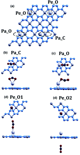
The adsorption energy, CO2 height, and CO2 bond angle for the four configurations were calculated (Table 5). Of these four positions, CO2 molecules only chemisorbed to the Li-doped beryllonitrene when placed in positions Pa_O and Pe_O1. The adsorption energy for CO2 at position Pa_C is 0.0002 Ha, which is positive, suggesting that this is not a viable position for carbon dioxide to adsorb onto beryllonitrene. In this position, the oxygen atoms were pulled closer to the lithium atom than the carbon atom, resulting in a bond angle of 142.192°. The adsorption energy for CO2 at position Pe_O2 is −0.0012, which is negative, suggesting that carbon dioxide is attracted to beryllonitrene at this location. However, the adsorption energy is smaller than the chemisorption threshold of −0.011 Ha, indicating that carbon dioxide is only weakly physisorbed to beryllonitrene at this location. The adsorption energy for CO2 at position Pa_O is −0.0155 Ha, while the adsorption energy for CO2 at position Pe_O1 is −0.0145 Ha. Both of these adsorption energies are greater than the chemisorption threshold of 0.011 Ha, so the CO2 molecule is chemisorbed to Li-doped beryllonitrene at these two positions.10,25 For comparison, the adsorption energies for carbon dioxide on N-doped, S-doped, and N–S-dual-doped graphene are −0.0055 Ha, −0.0040 Ha, and −0.0066 Ha respectively.38 The successful chemisorption positions all had the oxygen pointed towards the lithium atom, which suggests that the oxygen atoms are attracted to the lithium atom.
| Position | Eads (Ha) | d (Å) | ∠O–C–O (°) |
|---|---|---|---|
| Pa_C | 0.0002 | 2.15 | 142 |
| Pa_O | −0.0155 | 1.91 | 153 |
| Pe_O1 | −0.0145 | 1.90 | 165 |
| Pe_O2 | −0.0012 | 9.23 | 180 |
Since CO2 had the greatest adsorption energy when placed in position Pa_O, this configuration appears to be the most stable configuration, so it was used for further calculations.
3.2 Charge transfer
The charge transfer diagram was plotted for the adsorption of CO2 onto Li-doped beryllonitrene at site Pa_O, as shown in Fig. 7. There appears to be a transfer of electrons away from the carbon atom and towards the oxygen atoms, particularly the atom facing the lithium dopant. This makes sense because oxygen is much more electronegative than carbon and lithium, so it has a much stronger attraction towards the electrons. The existence of the charge transfer indicates that a chemical bond was formed between the carbon dioxide molecule and the Li-doped beryllonitrene.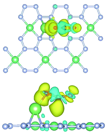 | ||
| Fig. 7 Top and side view of charge transfer isosurface for adsorption of CO2 on Li-doped beryllonitrene. Yellow areas are charge gained and blue areas are charge lost. | ||
3.3 PDOS
To further understand the adsorption of CO2 onto Li-doped beryllonitrene, the projected density of states (PDOS) was plotted for pristine beryllonitrene, Li-doped beryllonitrene with Li at position H as shown in Fig. 2(a), and Li-doped beryllonitrene with carbon dioxide at Pa_O as shown in Fig. 6(a).For pristine beryllonitrene, the 2p orbital of nitrogen (green line) and the 2s orbital for beryllium (blue line) were plotted, as shown in Fig. 8(a). There appears to be significant overlap between the 2p orbital of nitrogen and the 2s orbital of beryllium in the range from about −10 to −5 eV. This overlap indicates that the beryllium and nitrogen atoms in the beryllonitrene monolayer are chemically bonded, which means that the beryllonitrene monolayer is a plausible monolayer.
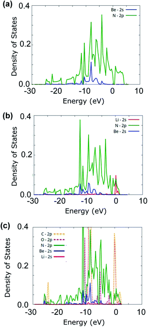 | ||
| Fig. 8 Projected density of states (PDOS) for (a) pristine beryllonitrene, (b) Li-doped beryllonitrene, and (c) Li-doped beryllonitrene with carbon dioxide adsorbed. | ||
For Li-doped beryllonitrene, the 2s orbital of lithium (red line) was also plotted alongside nitrogen and beryllium, as shown in Fig. 8(b). The addition of the lithium dopant causes the PDOS to shift towards the left (towards negative energy). The PDOS for the 2s orbital of lithium (red line) has a major peak at around 0 eV, which overlaps with the PDOS spectra of nitrogen, indicating that a chemical bond has formed between the lithium dopant and the nitrogen atoms in beryllonitrene. Lithium does not demonstrate much overlap with beryllium. This matches with the relaxed atomic structure because it shows that lithium was bonded to beryllonitrene via the four nitrogen atoms in the Be2N4 hexagon, as shown in Fig. 4(a).
The PDOS spectra was also plotted for the Li-doped beryllonitrene with a carbon dioxide molecule adsorbed at Pa_O, as shown in Fig. 8(c). In addition to the spectra for lithium, nitrogen, and beryllium, the 2p orbitals of oxygen (pink line) and carbon (orange line) were also plotted. Lithium's largest peaks were located at around 2 and −10 eV, and they had significant overlap with the carbon and oxygen molecules at these peaks. This suggests that the carbon dioxide molecule was chemically bonded to the lithium atom. The PDOS spectra of nitrogen also overlapped with lithium at these peaks, indicating that the lithium dopant was still bound to the beryllonitrene. These results show that carbon dioxide was able to successfully chemically bond to Li-doped beryllonitrene.
3.4 Band structure
In order to better understand the electronic properties of the materials, the band structure was plotted for pristine beryllonitrene, Li-doped beryllonitrene, and Li-doped beryllonitrene with CO2 adsorbed at Pa_O. Fig. 9 shows the calculated band structures for these materials.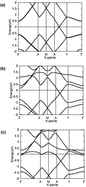 | ||
| Fig. 9 Band structure for (a) pristine beryllonitrene, (b) Li-doped beryllonitrene, and (c) Li-doped beryllonitrene with carbon dioxide adsorbed. | ||
The calculated band structure for a 2 × 2 supercell of pristine beryllonitrene is in Fig. 9(a), and it shows that beryllonitrene is a zero-gap semimetal with a Dirac-point between the A and Y k-points, which is consistent with previous results.43 The band structure for Li-doped beryllonitrene shown in Fig. 9(b) shows that after the lithium dopant is added to the beryllonitrene, the half-filled band from lithium lies entirely above the Fermi level. This means that lithium doping changes beryllonitrene from a semimetal to a metal. Fig. 9(c) shows the band structure of Li-doped beryllonitrene after carbon dioxide is adsorbed at site Pa_O. The two bands above the Fermi level appear to have been changed significantly, indicating that the adsorption of CO2 changes the electronic structure of Li-doped beryllonitrene.
Since Li-doped beryllonitrene exhibits metallic behavior, it could potentially be used as a charge-modulated CO2 capture material. Several other metallic materials have already been theoretically tested for charge-modulated CO2 capture.29,59
4 Conclusion
In summary, we used first principle calculations to determine the carbon dioxide capture ability of pristine beryllonitrene and Li-doped beryllonitrene. The atomic structure, adsorption energy, charge transfer, projected density of states, and band structure were analyzed to determine the viability of carbon dioxide adsorption. We found that pristine beryllonitrene demonstrated very weak attraction towards carbon dioxide. In order to enhance the carbon dioxide adsorption ability, we doped beryllonitrene with three different dopants: lithium, calcium, and aluminum. Calcium and aluminum were unable to spontaneously adsorb, but lithium was able to strongly chemisorb onto pristine beryllonitrene, producing Li-doped beryllonitrene. Lithium doping appeared to greatly enhance the carbon dioxide capture ability of beryllonitrene since carbon dioxide had an adsorption energy of −0.0155 Ha on Li-doped beryllonitrene, meaning that the CO2 molecule was chemisorbed. The charge transfer, projected density of states, and band structure diagrams show that the adsorption of carbon dioxide greatly change the electronic structure of the Li-doped beryllonitrene, suggesting that carbon dioxide is strongly chemisorbed onto the surface. These results demonstrate that Li-doped beryllonitrene is a possible candidate for application in CO2 capture.In our study, we did not consider whether or not the adsorption of carbon dioxide on these beryllonitrene monolayers was reversible. Typically, a certain amount of energy is required in order for the carbon dioxide to be removed. Future studies could explore the possibility of charge-controlled or strain-controlled CO2 capture using beryllonitrene for easier regeneration. Additionally, the calculations performed in this study were only theoretical. In the future, these results can be applied to experimental carbon dioxide adsorbents. In order to maximize the abilities of beryllonitrene, future research could also be done to investigate the effects of vacancies and other dopants on the CO2 capture ability of beryllonitrene.
Author contributions
Andrew Pu: conceptualization, data curation, formal analysis, investigation, methodology, writing – original draft. Xuan Luo: resources, supervision, validation, writing – review & editing.Conflicts of interest
The authors have no conflicts of interest to declare.Acknowledgements
Thank you to Dr Gefei Qian for providing software programs used in the study.Notes and references
- T. J. Crowley, Science, 2000, 289, 270–277 CrossRef CAS PubMed.
- E. G. G. Emissions and C. Change, available at, Google Scholar, 2017.
- E. Bekkers, J. F. Francois and H. Rojas-Romagosa, Econ. J., 2018, 128, 1095–1127 CrossRef.
- M. Benzie, A. Harvey, K. Burningham, N. Hodgson and A. Siddiqi, Vulnerability to heatwaves and drought: adaptation to climate change, The Joseph Rowntree Foundation, York, UK, 2011 Search PubMed.
- Q. Zhou, J. Koiwanit, L. Piewkhaow, A. Manuilova, C. Chan, M. Wilson and P. Tontiwachwuthikul, Energy Procedia, 2014, 63, 7452–7458 CrossRef CAS.
- M. Kanniche, R. Gros-Bonnivard, P. Jaud, J. Valle-Marcos, J.-M. Amann and C. Bouallou, Appl. Therm. Eng., 2010, 30, 53–62 CrossRef CAS.
- C.-H. Yu, C.-H. Huang and C.-S. Tan, et al., Aerosol Air Qual. Res., 2012, 12, 745–769 CrossRef CAS.
- G. T. Rochelle, Science, 2009, 325, 1652–1654 CrossRef CAS PubMed.
- R. S. Haszeldine, Science, 2009, 325, 1647–1652 CrossRef CAS PubMed.
- S. A. Tawfik, X. Cui, S. Ringer and C. Stampfl, RSC Adv., 2015, 5, 50975–50982 RSC.
- M. Signorile, J. G. Vitillo, M. D'Amore, V. Crocellà, G. Ricchiardi and S. Bordiga, J. Phys. Chem. C, 2019, 123, 17214–17224 CrossRef CAS.
- L. Mino, G. Spoto and A. M. Ferrari, J. Phys. Chem. C, 2014, 118, 25016–25026 CrossRef CAS.
- M. Ishibashi, H. Ota, N. Akutsu, S. Umeda, M. Tajika, J. Izumi, A. Yasutake, T. Kabata and Y. Kageyama, Energy Convers. Manage., 1996, 37, 929–933 CrossRef CAS.
- Y. Takamura, J. Aoki, S. Uchida and S. Narita, Can. J. Chem. Eng., 2001, 79, 812–816 CrossRef CAS.
- B. Metz, O. Davidson, H. De Coninck, M. Loos and L. Meyer, IPCC special report on carbon dioxide capture and storage, Cambridge, Cambridge University Press, 2005 Search PubMed.
- K. S. Novoselov, A. K. Geim, S. V. Morozov, D.-e. Jiang, Y. Zhang, S. V. Dubonos, I. V. Grigorieva and A. A. Firsov, science, 2004, 306, 666–669 CrossRef CAS PubMed.
- B. Shivananju, H. Y. Hoh, W. Yu and Q. Bao, in Fundamentals and Sensing Applications of 2D Materials, Elsevier, 2019, pp. 379–406 Search PubMed.
- T. Wehling, K. Novoselov, S. Morozov, E. Vdovin, M. Katsnelson, A. Geim and A. Lichtenstein, Nano Lett., 2008, 8, 173–177 CrossRef CAS PubMed.
- Y. Jiao, A. Du, Z. Zhu, V. Rudolph, G. Q. M. Lu and S. C. Smith, Catal. Today, 2011, 175, 271–275 CrossRef CAS.
- S. M. Aghaei, M. Monshi, I. Torres, M. Banakermani and I. Calizo, Phys. Lett. A, 2018, 382, 334–338 CrossRef.
- T. Hussain, T. Kaewmaraya, S. Chakraborty and R. Ahuja, J. Phys. Chem. C, 2016, 120, 25256–25262 CrossRef CAS.
- W. Xia, W. Hu, Z. Li and J. Yang, Phys. Chem. Chem. Phys., 2014, 16, 22495–22498 RSC.
- N. Yu, L. Wang, M. Li, X. Sun, T. Hou and Y. Li, Phys. Chem. Chem. Phys., 2015, 17, 11700–11704 RSC.
- Q. Sun, G. Qin, Y. Ma, W. Wang, P. Li, A. Du and Z. Li, Nanoscale, 2017, 9, 19–24 RSC.
- K. Jia and X. Luo, PeerJ Mater. Sci., 2020, 2, e3 CrossRef.
- G. Rao, T. Hussain, M. S. Islam, M. Sagynbaeva, D. Gupta, P. Panigrahi and R. Ahuja, Nanotechnology, 2015, 27, 015502 CrossRef PubMed.
- Y. Yong, X. Su, H. Cui, Q. Zhou, Y. Kuang and X. Li, ACS Omega, 2017, 2, 8888–8895 CrossRef CAS PubMed.
- X. Fu, H. Yang, L. Fu, C. He, J. Huo, J. Guo and L. Li, Chin. Chem. Lett., 2021, 32, 1089–1094 CrossRef CAS.
- H. Zhang, H. Xiong and W. Liu, Crystals, 2021, 11, 543 CrossRef CAS.
- M. H. Darvishnejad and A. Reisi-Vanani, Comput. Mater. Sci., 2020, 176, 109539 CrossRef CAS.
- M. H. Darvishnejad and A. Reisi-Vanani, J. CO2 Util., 2021, 46, 101469 CrossRef CAS.
- S. Zhou, M. Wang, S. Wei, S. Cao, Z. Wang, S. Liu, D. Sun and X. Lu, Mater. Today Phys., 2021, 16, 100301 CrossRef CAS.
- W. Luo, H. Wang, Z. Wang, G. Liu, S. Liu and C. Ouyang, Phys. Chem. Chem. Phys., 2020, 22, 8864–8869 RSC.
- X. Tan, L. Kou, H. A. Tahini and S. C. Smith, Sci. Rep., 2015, 5, 1–8 Search PubMed.
- G. Qin, Q. Cui, W. Wang, P. Li, A. Du and Q. Sun, ChemPhysChem, 2018, 19, 2788–2795 CrossRef CAS PubMed.
- C. He, M. Zhang, T. Li and W. Zhang, Appl. Surf. Sci., 2020, 505, 144619 CrossRef CAS.
- C. He, M. Zhang, T. Li and W. Zhang, J. Mater. Chem. C, 2020, 8, 6542–6551 RSC.
- J. Li, M. Hou, Y. Chen, W. Cen, Y. Chu and S. Yin, Appl. Surf. Sci., 2017, 399, 420–425 CrossRef CAS.
- V. Chandra, S. U. Yu, S. H. Kim, Y. S. Yoon, D. Y. Kim, A. H. Kwon, M. Meyyappan and K. S. Kim, Chem. Commun., 2012, 48, 735–737 RSC.
- Y. Liu, L. Li, Q. Li, J. Lin, Z. Guo, X. Zhang, Z. Lu, Y. Ma, Y. Huang and C. Tang, Appl. Surf. Sci., 2021, 556, 149775 CrossRef.
- J. Zhu, A. Chroneos and U. Schwingenschlögl, Phys. Status Solidi RRL, 2016, 10, 458–461 CrossRef CAS.
- M. Bykov, T. Fedotenko, S. Chariton, D. Laniel, K. Glazyrin, M. Hanfland, J. S. Smith, V. B. Prakapenka, M. F. Mahmood and A. F. Goncharov, et al., Phys. Rev. Lett., 2021, 126, 175501 CrossRef CAS PubMed.
- A. Bafekry, C. Stampfl, M. Faraji, M. Yagmurcukardes, M. Fadlallah, H. Jappor, M. Ghergherehchi and S. Feghhi, Appl. Phys. Lett., 2021, 118, 203103 CrossRef CAS.
- W. Kohn and L. J. Sham, Phys. Rev., 1965, 140, A1133 CrossRef.
- P. Hohenberg and W. Kohn, Phys. Rev., 1964, 136, B864 CrossRef.
- X. Gonze, B. Amadon, G. Antonius, F. Arnardi, L. Baguet, J.-M. Beuken, J. Bieder, F. Bottin, J. Bouchet and E. Bousquet, et al., Comput. Phys. Commun., 2020, 248, 107042 CrossRef CAS.
- A. H. Romero, D. C. Allan, B. Amadon, G. Antonius, T. Applencourt, L. Baguet, J. Bieder, F. Bottin, J. Bouchet and E. Bousquet, et al., J. Chem. Phys., 2020, 152, 124102 CrossRef CAS PubMed.
- X. Gonze, F. Jollet, F. A. Araujo, D. Adams, B. Amadon, T. Applencourt, C. Audouze, J.-M. Beuken, J. Bieder and A. Bokhanchuk, et al., Comput. Phys. Commun., 2016, 205, 106–131 CrossRef CAS.
- X. Gonze, B. Amadon, P.-M. Anglade, J.-M. Beuken, F. Bottin, P. Boulanger, F. Bruneval, D. Caliste, R. Caracas and M. Côté, et al., Comput. Phys. Commun., 2009, 180, 2582–2615 CrossRef CAS.
- X. Gonze, Zeitschrift für Kristallographie-Crystalline Materials, 2005, 220, 558–562 CrossRef CAS.
- X. Gonze, J.-M. Beuken, R. Caracas, F. Detraux, M. Fuchs, G.-M. Rignanese, L. Sindic, M. Verstraete, G. Zerah and F. Jollet, et al., Comput. Mater. Sci., 2002, 25, 478–492 CrossRef.
- J. P. Perdew, K. Burke and M. Ernzerhof, Phys. Rev. Lett., 1996, 77, 3865 CrossRef CAS PubMed.
- P. E. Blöchl, Phys. Rev. B: Condens. Matter Mater. Phys., 1994, 50, 17953 CrossRef PubMed.
- M. Torrent, F. Jollet, F. Bottin, G. Zérah and X. Gonze, Comput. Mater. Sci., 2008, 42, 337–351 CrossRef CAS.
- N. Holzwarth, A. Tackett and G. Matthews, Comput. Phys. Commun., 2001, 135, 329–347 CrossRef CAS.
- J. D. Head and M. C. Zerner, Chem. Phys. Lett., 1985, 122, 264–270 CrossRef CAS.
- B. Mortazavi, F. Shojaei and X. Zhuang, Mater. Today Nano, 2021, 100125 CrossRef.
- A. Klotz, T. Ward and E. Dartois, Astron. Astrophys., 2004, 416, 801–810 CrossRef CAS.
- X. Tan, H. A. Tahini and S. C. Smith, ACS Appl. Mater. Interfaces, 2017, 9, 19825–19830 CrossRef CAS PubMed.
Footnote |
| † These authors contributed equally to this work. |
| This journal is © The Royal Society of Chemistry 2021 |

