 Open Access Article
Enhanced photocatalytic hydrogen production of MoS2 sheet/carbon nanofiber using rapid electron transport of Mo6+ and carbon nanofiber†
Jianfeng Qiu ab,
Jiaqi Panac,
Shunhang Wei
 b,
Qifeng Liangb,
Yawei Wangd,
Rong Wu
 e and
Chaorong Li*ac
aCollege of Textile Science and Engineering, Zhejiang Sci-Tech University, Hangzhou, 310018, PR China. E-mail: crli@zstu.edu.cn
bDepartment of Physics, Shaoxing University, Shaoxing 312000, PR China
cKey Laboratory of Optical Field Manipulation of Zhejiang Province, Department of Physics, Zhejiang Sci-Tech University, Hangzhou 310018, P. R. China
dSchool of Chemistry and Chemical Engineering, Jiujiang University, Jiujiang 332005, PR China
eSchool of Physics Science and Technology, Xinjiang University, Urumqi 830000, PR China
First published on 30th November 2021
Abstract
Normal MoS2 exhibits a low photocatalytic performance for H2 production owing to the deficiency of the active sites and the poor electrical conductance. In this work, MoS2 anchored on the surface of the carbon nanofibers was designed to enhance the activity of the exposed edge and the electrical conductivity at the same time. The oxidation of the surface Mo atoms increases the activity of the exposed edge of the MoS2. The introduction of carbon nanofibers facilitates the effective transportation of the electron–hole pairs by enhancing the electrical conductivity. As a result, the introduction of carbon nanofibers and Mo6+ can facilitate the electron–hole pair separation to enhance the photocatalytic hydrogen evolution reaction (HER) performance (to eight fold more than normal MoS2).
Introduction
Owing to being clean, cheap and sustainable, H2 evolution using photocatalytic water splitting is regarded as a promising technology to convert solar energy.1–4 In recent decades, a large number of semiconductor photocatalysts have been developed for photocatalytic hydrogen evolution, for example, metal oxides,5,6 sulfides,7–10 and oxynitrides.11,12 Among these, MoS2, a typical two-dimensional (2D) sulfide, has attracted considerable attention owing to its suitable band gap potential and sufficient hydrogen evolution reaction (HER) active sites.13–15 However, restricted by the high photo-generated charge carrier recombination,16 the photocatalytic HER performance of single MoS2 can barely meet the needs of actual applications. Thus, improving the photo-generated charge carrier separation is the most significant issue for this system.17 Also, the increased HER active sites and dispersibility are important for further ameliorating the HER performance.18,19As reported, the edges S atoms are regarded as efficient active sites for the HER,13 and significant efforts have been made to expose more efficient edge S atoms active sites. For example, Li et al. have prepared N-doped MoS2 nanosheets with an enhanced HER performance,20 Kong et al. reported vertically aligned layers of crystalline MoS2 with a remarkable HER performance,21 and other specific MoS2 nanostructures, including nanosheets, nanorods, nanotubes, and so on, have been reported previously.22–24 However, the HER performance is expected to improve further, especially for promoting the charge carrier separation.25 As reported, Mo6+, with unique redox properties, was found to play a significant role in the photocatalytic reactions.26,27 Therefore, introducing Mo6+ into MoS2 may effectively improve the active sites of the Mo edge. On the other hand, rapid transportation of the photo-generated electron is also an effective method for restraining photo-generated charge carrier recombination,28 therefore, a series of co-catalyst or metallic carriers have been reported as promising candidates, such as NiS2, MoC2 or CoS,29–31 and so forth. Currently, highly carbonated carbon nanofibers,32 with a high conductivity, low cost, and which are environmentally friendly, are a hot topic of research. In particular, the unique electronic structure of the carbon fibers can maintain a good physical–chemical stability during the rapid HER process and charge carrier transportation.33–35
Additionally, the dispersibility is another important factor for photocatalysts, as owing to the large specific surface areas and high surface activity, the nano-catalysts can easily aggregate,36 leading to inactivation of the nano-catalyst, decreasing the catalytic activity. Therefore, highly dispersive and stable carriers are regarded as having indispensable properties for a highly photocatalytically active systems.37 Herein, carbon nano-fibers, prepared using the electrospinning–carbonization method,38 were fabricated and possess both toughness and dispersibility. These properties can provide sufficient specific surface areas for MoS2 deposition and enough dispersibility to prevent aggregation,33 and are reported to be an ideal carrier.39,40 Furthermore, this fiber system can be directly recycled from the reaction solution, these properties can decrease the cost, increasing the competitiveness.41
In this work, we report the growth of MoS2 (MS)/carbon nanofibers (CNF) using the electrospinning–carbonization method. Herein, the activity of the MS can be improved by changing the surface valence state (Mo6+), and carbon nanofibers can enhance the electron transportation to restrain the charge carrier recombination and increase the dispersibility. As revealed, the photocatalytic HER activity of the as-prepared MS/CNF exhibits a significantly enhancement of about eight fold upon introduction of the carbon nanofibers.
Experimental
Chemicals
Polyacrylonitrile (PAN; Mw = 150![[thin space (1/6-em)]](https://www.rsc.org/images/entities/char_2009.gif) 000; J&K Scientific), N,N-dimethylformamide (DMF; AR; Aladdin), molybdenum sulfide (MoS2; 99.5% metals basis; Aladdin), triethanolamine (AR; Aladdin), and absolute ethanol (AR; Aladdin).
000; J&K Scientific), N,N-dimethylformamide (DMF; AR; Aladdin), molybdenum sulfide (MoS2; 99.5% metals basis; Aladdin), triethanolamine (AR; Aladdin), and absolute ethanol (AR; Aladdin).
Preparation
Polyacrylonitrile (1 g) was added into DMF (10 mL) solution and magnetically stirred for 10 h. MoS2 (0.2 g) was added into the obtained transparent solution and stirring was continued for 24 h to form a homogenous solution for electrospinning. The obtained homogenous solution was fed into a syringe pump with a 17 kV voltage source. The distance between the needle tip and the collector was 15 cm. The feeding rate of the solution in the syringe was controlled at 1.0 mL h−1. The collected products were calcined at 230 °C in air for 3 h and then calcined at 800 °C in nitrogen for 2 h. A schematic illustration is shown in Fig. 1.Characterization
The crystalline phases were characterized using X-ray powder diffractometry (XRD, Empyrean). The morphology of the samples was obtained using field emission scanning electron microscopy (FESEM, SIGMA 300) and high-resolution transmission electron microscopy (HRTEM, JEM-2100 F). The elemental chemical states of the samples were examined using X-ray photoelectron spectroscopy (XPS, Thermo ESCALAB250). UV-vis diffuse reflection spectra (DRS) were obtained using a UV-3600 plus spectrophotometer (Shimadzu). The photoluminescence (PL) spectra were measured using a fluorescence spectrophotometer (Hitachi F-7000) with an excitation wavelength of 350 nm. The electrochemical impedance spectroscopy was measured using a CHI 660 electrochemical workstation in a conventional three electrode system.Photocatalytic activity measurements
Experiments were carried out in a top irradiation-type glass reactor connected to a gas-closed circulation and evacuation system (Labsolar 6A, Perfect Light, China). A 300 W xenon lamp (PLX-SXE300, Perfect Light) was used as a light source. In a typical measurement, 50 mg of the catalyst was suspended in 100 mL of a 10 vol% aqueous solution of triethanolamine (sacrificial reagent). The H2 produced in the reactor was analyzed using an online gas chromatograph (GC7806, shiweipx, China).Results and discussion
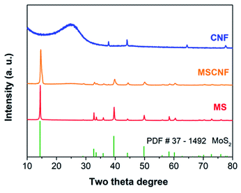
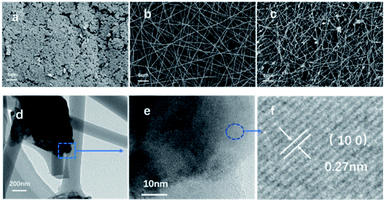
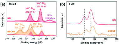
The XRD and Raman spectra results (Fig. 2 and S1†) show that the MoS2 (represented by MS) retains the original structure after high temperature carbonization and deposition around the carbon nanofibers (represented as CNF). It should be noted that the diffraction peaks exhibit an obvious broadening, which indicates that the nanocrystal size of the MS decreases after deposition around the carbon nanofibers.42 The morphologies of MS and MSCNF were characterized using FESEM and HRTEM. As shown, the normal MoS2 (Fig. 3a) is a typical bulk sample, and the carbon nanofiber (Fig. 3b) with a diameter of approximately 200 nm is smooth and uniform. Significantly, with the formation of the MoS2/carbon nanofibers, the size of the MoS2 nanosheets shows an obvious decrease (Fig. 3c), which is beneficial for the HER performance and corresponds to the XRD results. The HRTEM image of MSCNF (Fig. 3e and f) shows that the 0.27 nm lattice spacing corresponds to the (100) facets of the MS, which can further confirm the deposition of MS around the CNF.X-ray photoelectron spectroscopy (XPS) analysis was used to investigate the surface chemical states of MS and MSCNF, and is shown in Fig. 4a and b. As revealed, the binding energies of Mo 3d3/2 and Mo 3d5/2 in the MS located at 232.94 and 229.79 eV can be ascribed to Mo4+.19 After the MS is anchored onto the surface of CNF and carbonized, the new peaks at 236.02 and 232.84 eV can be assigned to the increased Mo6+ and its proportion is about approximately 74% (calculated using the peak area ratio of Mo 3d),43 indicating that the Mo atoms on the surface are oxidized during the carbonization process, which is beneficial for charge carrier transportation.44 Based on the integrated peak areas of the Mo 3d and S 2p doublets, the S![[thin space (1/6-em)]](https://www.rsc.org/images/entities/char_2009.gif) :
:![[thin space (1/6-em)]](https://www.rsc.org/images/entities/char_2009.gif) Mo ratio decreased from 1.81
Mo ratio decreased from 1.81![[thin space (1/6-em)]](https://www.rsc.org/images/entities/char_2009.gif) :
:![[thin space (1/6-em)]](https://www.rsc.org/images/entities/char_2009.gif) 1 in MS to 1.58
1 in MS to 1.58![[thin space (1/6-em)]](https://www.rsc.org/images/entities/char_2009.gif) :
:![[thin space (1/6-em)]](https://www.rsc.org/images/entities/char_2009.gif) 1 in MSCNF, which indicates that the S atoms on the surface are also oxidized. The decrease in the peak of S 2s located at 226.96 eV further confirms the deduction.18 In addition, the electron paramagnetic resonance spectroscopy (EPR) result (Fig. S2†) shows that no S-vacancy is generated after calcination. A shift in the S 2p peaks in the MS and MSCNF was also found (Fig. 4b), indicating that some electronic interactions and transfers occur between the MS and CNF.
1 in MSCNF, which indicates that the S atoms on the surface are also oxidized. The decrease in the peak of S 2s located at 226.96 eV further confirms the deduction.18 In addition, the electron paramagnetic resonance spectroscopy (EPR) result (Fig. S2†) shows that no S-vacancy is generated after calcination. A shift in the S 2p peaks in the MS and MSCNF was also found (Fig. 4b), indicating that some electronic interactions and transfers occur between the MS and CNF.
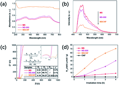
Fig. 5a shows the UV-vis absorption spectra of the as-prepared MS, the MS calcined at 800 °C in nitrogen for 2 h (called MS-800), and MSCNT. As shown, the MS-800 has a stronger light absorption than that of the single MS, which can be assigned to the presence of Mo6+. After the MS is deposited on the CNT, the enhanced absorption in the full spectra can be clearly observed, which is ascribed to the full spectrum absorption of the carbon nanofibers. PL is used to investigate the separation efficiency of the photo-generated carriers (Fig. 5b). Herein, the weaker PL intensity corresponds to the lower recombination.45,46 It can be obviously seen that the intensity of MS-800 is lower than that of MS, indicating that the surface oxidation can improve the activity of the exposed edge of the MS to reduce the recombination of the photo-generated carriers effectively. The intensity of MSCNF is further reduced, which could be attributed to the fact that the electrons excited from MS would transfer to CNF quickly, avoiding a direct recombination with the corresponding holes. The results of the electrochemical impedance spectroscopy (EIS) further demonstrate the deduction (Fig. 5c). An equivalent circuit is proposed to fit the spectra. The equivalent circuit for the MS and MS-800 samples is composed of a resistor Rs (the solution resistance between the Ag/AgCl reference electrode and the working electrode) and an electrode–electrolyte interfacial charge transfer resistor Rct. Obviously, compared with MS and MS-800, the MSCNF sample has an extra electron transfer resistor Rect, and the resistance value is much smaller than that of MS and MS-800. This indicates that there is a charge transfer between the MoS2 and carbon fiber, and the high conductivity of the carbon fiber can promote the separation of the photo-generated electron–hole pairs.9,47–49 Fig. 5d displays the H2 evolution activity of the different samples. The H2 evolution rate of MSCNF is up to about eight times that of MS and is about two times that of MS-800. As shown in Fig. S3,† in consecutive 12 h (3 cycles) hydrogen production processes, the MSCNF sample exhibits a commendable stability. Herein, a possible photocatalytic mechanism can be deduced. The results obtained using EIS and PL indicate that the carrier migration and separation of MoS2 shows little change before and after calcination. However, the H2 evolution rate of MS-800 can be up to about four times that of MS, therefore the main reason for the enhanced photocatalytic performance is that the oxidation of the Mo atoms increases the active sites of MoS2.50 The introduction of CNF further reduces the PL intensity and improves the photocatalytic activity, indicating that CNF accelerated the carrier migration and separation efficiency owing to its high conductivity.
 | ||
| Fig. 5 (a) UV-vis diffuse reflectance spectra of the samples; (b) PL spectra of the samples; (c) Nyquist plots of the samples; and (d) temporal photocatalytic H2 evolution of the samples. | ||
Conclusions
In summary, we have developed a simple method to prepare MoS2 sheet/carbon nanofibers. The surface Mo and S atoms are oxidized by calcination in nitrogen at a high temperature, which can increase the activity of the exposed edge of MS. Herein, the introduction of CNF and increased Mo6+ can enhance the photo-generated charge carrier transportation to facilitate effective electron–hole pairs separation, which is beneficial for enhancing the HER performance. As a consequence, an enhanced H2 generation was achieved in MSCNF (eight fold more than normal MoS2). This work may provide a novel avenue for commercialization of the photocatalyst.Conflicts of interest
There are no conflicts to declare.Acknowledgements
This work was supported by the National Natural Science Foundation of China (Grant No. 51672249, 51802282, 11804301, 52062023 and 22066024) and the Fundamental Research Funds of Zhejiang Sci-Tech University (No. 2019Q062).Notes and references
- P. Taberna, J. B. Barbosa, A. Balocchi, I. Gerber, K. Urita, A. Barnabe, X. Marie and J. Chane-Ching, Chem. Eng. J., 2021, 424, 130433 CrossRef CAS.
- S. Wei, S. Chang, J. Qian and X. Xu, Small, 2021, 17, 2100084 CrossRef CAS PubMed.
- W. Zhong, X. Wu, Y. Liu, X. Wang, J. Fan and H. Yu, Appl. Catal., B, 2021, 280, 119455 CrossRef CAS.
- Z. Wang, H. H. Wu, Q. Li, F. Besenbacher, Y. Li, X. C. Zeng and M. Dong, Adv. Sci., 2020, 7, 1901382 CrossRef CAS PubMed.
- S. Wei, S. Ni and X. Xu, Chin. J. Catal., 2018, 39, 510–516 CrossRef CAS.
- H. Yan and H. Yang, J. Alloys Compd., 2011, 509, L26–L29 CrossRef CAS.
- L. J. Zhang, S. Li, B. K. Liu, D. J. Wang and T. F. Xie, ACS Catal., 2014, 4, 3724–3729 CrossRef CAS.
- K. Chang, Z. Mei, T. Wang, Q. Kang, S. Ouyang and J. Ye, ACS Nano, 2014, 8, 7078–7087 CrossRef CAS PubMed.
- Z. Wang, X. Xiong, J. Li and M. Dong, Mater. Today Phys., 2021, 16, 100290 CrossRef CAS.
- Z. Wang, Q. Li, H. Xu, C. Dahl-Petersen, Q. Yang, D. Cheng, D. Cao, F. Besenbacher, J. V. Lauritsen and S. Helveg, Nano Energy, 2018, 49, 634–643 CrossRef CAS.
- C. Pan, T. Takata, K. Kumamoto, S. S. K. Ma, K. Ueda, T. Minegishi, M. Nakabayashi, T. Matsumoto, N. Shibata and Y. Ikuhara, J. Mater. Chem. A, 2016, 4, 4544–4552 RSC.
- C. Pan, T. Takata, M. Nakabayashi, T. Matsumoto, N. Shibata, Y. Ikuhara and K. Domen, Angew. Chem., Int. Ed., 2015, 54, 2955–2959 CrossRef CAS PubMed.
- Z. Li, X. Meng and Z. Zhang, J. Photochem. Photobiol., C, 2018, 35, 39–55 CrossRef CAS.
- Y.-J. Yuan, P. Wang, Z. Li, Y. Wu, W. Bai, Y. Su, J. Guan, S. Wu, J. Zhong and Z.-T. Yu, Appl. Catal., B, 2019, 242, 1–8 CrossRef CAS.
- F.-J. Zhang, X. Li, X.-Y. Sun, C. Kong, W.-J. Xie, Z. Li and J. Liu, Appl. Surf. Sci., 2019, 487, 734–742 CrossRef CAS.
- S. Y. Qi, X. T. Liu, N. L. Ma and H. Y. Xu, Chem. Phys. Lett., 2021, 763, 138203 CrossRef CAS.
- Y. R. Sun, C. Xue, L. Chen, Y. K. Li, S. W. Guo, Y. L. Shen, F. Dong, G. S. Shao and P. Zhang, Sol. RRL, 2021, 5, 2000722 CrossRef CAS.
- J. Ekspong, T. Sharifi, A. Shchukarev, A. Klechikov, T. Wågberg and E. Gracia-Espino, Adv. Funct. Mater., 2016, 26, 6766–6776 CrossRef CAS.
- Y. Chen, F. Su, H. Xie, R. Wang, C. Ding, J. Huang, Y. Xu and L. Ye, Chem. Eng. J., 2021, 404, 126498 CrossRef CAS.
- R. Li, L. Yang, T. Xiong, Y. Wu, L. Cao, D. Yuan and W. Zhou, J. Power Sources, 2017, 356, 133–139 CrossRef CAS.
- D. Kong, H. Wang, J. J. Cha, M. Pasta, K. J. Koski, J. Yao and Y. Cui, Nano Lett., 2013, 13, 1341–1347 CrossRef CAS PubMed.
- D. Voiry, M. Salehi, R. Silva, T. Fujita, M. Chen, T. Asefa, V. B. Shenoy, G. Eda and M. Chhowalla, Nano Lett., 2013, 13, 6222–6227 CrossRef CAS PubMed.
- T. Sun, J. Wang, X. Chi, Y. Lin, Z. Chen, X. Ling, C. Qiu, Y. Xu, L. Song and W. Chen, ACS Catal., 2018, 8, 7585–7592 CrossRef CAS.
- M. Remskar, A. Mrzel, Z. Skraba, A. Jesih, M. Ceh, J. Demšar, P. Stadelmann, F. Lévy and D. Mihailovic, Science, 2001, 292, 479–481 CrossRef CAS PubMed.
- H. X. Fang, H. Guo, C. G. Niu, C. Liang, D. W. Huang, N. Tang, H. Y. Liu, Y. Y. Yang and L. Li, Chem. Eng. J., 2020, 402, 126185 CrossRef CAS.
- M. Matsuoka, T. Kamegawa, R. Takeuchi and M. Anpo, Catal. Today, 2007, 122, 39–45 CrossRef CAS.
- H. Jeziorowski and H. Knoezinger, J. Phys. Chem., 1979, 83, 1166–1173 CrossRef CAS.
- Y.-J. Yuan, Y. Yang, Z. Li, D. Chen, S. Wu, G. Fang, W. Bai, M. Ding, L.-X. Yang, D.-P. Cao, Z.-T. Yu and Z.-G. Zou, ACS Appl. Energy Mater., 2018, 1, 1400–1407 CrossRef CAS.
- J. Q. Pan, B. B. Wang, Z. J. Dong, C. Zhao, Z. Y. Jiang, C. S. Song, J. J. Wang, Y. Y. Zheng and C. R. Li, Int. J. Hydrogen Energy, 2019, 44, 19942–19952 CrossRef CAS.
- Q. Hu, X. Liu, B. Zhu, L. Fan, X. Chai, Q. Zhang, J. Liu, C. He and Z. Lin, Nano Energy, 2018, 50, 212–219 CrossRef CAS.
- Y. H. Song, Z. Mo, J. J. Fu, X. N. Zhang, X. J. She, J. J. Yuan, H. X. Chen, J. C. Qian, C. Q. Zhou, Y. S. Wu, W. S. Yang, H. M. Li and H. Xu, Colloids Surf., A, 2021, 617, 126151 CrossRef CAS.
- K. E. Greenstein, M. R. Nagorzanski, B. Kelsay, E. M. Verdugo, N. V. Myung, G. F. Parkin and D. M. Cwiertny, Environ. Sci.: Nano, 2021, 8, 711–722 RSC.
- Y. K. Kim, M. Kim, S.-H. Hwang, S. K. Lim, H. Park and S. Kim, Int. J. Hydrogen Energy, 2015, 40, 136–145 CrossRef CAS.
- M.-Q. Wang, C. Ye, H. Liu, M. Xu and S.-J. Bao, Angew. Chem., Int. Ed., 2018, 57, 1963–1967 CrossRef CAS PubMed.
- Y. K. Kim, S. K. Lim, H. Park, M. R. Hoffmann and S. Kim, Appl. Catal., B, 2016, 196, 216–222 CrossRef CAS.
- J.-J. Li, M. Zhang, B. Weng, J. Chen and H. Jia, J. Alloys Compd., 2020, 849 Search PubMed.
- P. Zhang, C. Shao, Z. Zhang, M. Zhang, J. Mu, Z. Guo and Y. Liu, Nanoscale, 2011, 3, 3357–3363 RSC.
- N. A. Garcia-Gomez, D. I. Garcia-Gutierrez, S. Sepulveda-Guzman and E. M. Sanchez, J. Mater. Sci.: Mater. Electron., 2013, 24, 3976–3984 CrossRef CAS.
- W. Guo, F. Zhang, C. Lin and Z. L. Wang, Adv. Mater., 2012, 24, 4761–4764 CrossRef CAS PubMed.
- Y. Gu, C. Li, J. Bai, J. Wang and T. Ma, Vacuum, 2016, 130, 1–6 CrossRef CAS.
- B. Pant, H. R. Pant, N. A. M. Barakat, M. Park, K. Jeon, Y. Choi and H.-Y. Kim, Ceram. Int., 2013, 39, 7029–7035 CrossRef CAS.
- P. Bindu and S. Thomas, J. Theor. Appl. Phys., 2014, 8, 123–134 CrossRef.
- Z. Chen, D. Cummins, B. N. Reinecke, E. Clark, M. K. Sunkara and T. F. Jaramillo, Nano Lett., 2011, 11, 4168–4175 CrossRef CAS PubMed.
- L. Yang, Y. Xiong, W. Guo, J. Guo, D. Gao, Y. Zhang and P. Xiao, Electrochim. Acta, 2017, 256, 268–277 CrossRef CAS.
- S. Wei, S. Chang, F. Yang, Z. Fu, G. Liu and X. Xu, Chem. Commun., 2021, 57, 4412–4415 RSC.
- S. Wei, J. Gao, P. Wu, B. Yao, H. Xu, Y. Tan, S. Liu, R. Wu, Y. Wang and L. Wang, Ceram. Int., 2021, 47, 28296–28303 CrossRef CAS.
- S. Wei, G. Zhang and X. Xu, Appl. Catal., B, 2018, 237, 373–381 CrossRef CAS.
- T. Qin, Z. Wang, Y. Wang, F. Besenbacher, M. Otyepka and M. Dong, Nano-Micro Lett., 2021, 13, 1–34 CrossRef PubMed.
- Y. Wang, L. Hao, Y. Zeng, X. Cao, H. Huang, J. Liu, X. Chen, S. Wei, L. Gan and P. Yang, J. Alloys Compd., 2021, 886, 161176 CrossRef CAS.
- F. Li, R. Tao, B. Cao, L. Yang and Z. Wang, Adv. Funct. Mater., 2021, 31, 2104367 CrossRef CAS.
Footnote |
| † Electronic supplementary information (ESI) available. See DOI: 10.1039/d1ra06938a |
| This journal is © The Royal Society of Chemistry 2021 |


