 Open Access Article
A PVA/LiCl/PEO interpenetrating composite electrolyte with a three-dimensional dual-network for all-solid-state flexible aluminum–air batteries
Li Chena,
Boqiao Lic,
Liangliang Zhu ab,
Xiaobin Dengb,
Xueyan Suna,
Yilun Liu
 c,
Chen Zhangd,
Wei Zhao
 *ab and
Xi Chen
 *e
*e
aSchool of Chemical Engineering, Northwest University, Xi'an 710069, China
bShaanxi Institute of Energy and Chemical Engineering, Xi'an 710069, China. E-mail: zhaowei3313@nwu.edu.cn
cSchool of Aerospace, Xi'an Jiaotong University, Xi'an 710049, China
dFirst Aircraft Institute of Aviation Industry Corporation, Xi'an 710089, China
eEarth Engineering Center, Center for Advanced Materials for Energy and Environment, Department of Earth and Environmental Engineering, Columbia University, New York, NY 10027, USA. E-mail: xichen@columbia.edu
First published on 13th December 2021
Abstract
Aluminum–air batteries are promising electronic power sources because of their low cost and high energy density. However, traditional aluminum–air batteries are greatly restricted from being used in the field of flexible electronics due to the rigid battery structure, and the irreversible corrosion of the anode by the alkaline electrolyte, which greatly reduces the battery life. To address these issues, a three-dimensional dual-network interpenetrating structure PVA/LiCl/PEO composite gel polymer electrolyte (GPE) is proposed. The gel polymer electrolyte exhibits good flexibility and high ionic conductivity (σ = 6.51 × 10⁻³ S cm−1) at room temperature. Meanwhile, benefiting from the high-performance GPE, an assembled aluminum–air coin cell shows a highest discharge voltage of 0.73 V and a peak power density (Pmax) of 3.31 mW cm−2. The Al specific capacity is as high as 735.2 mA h g−1. A flexible aluminum–air battery assembled using the GPE also performed stably in flat, bent, and folded states. This paper provides a cost-effective and feasible way to fabricate a composite gel polymer electrolyte with high performance for use in flexible aluminum–air batteries, suitable for a variety of energy-related devices.
Introduction
Metal–air batteries have become a hot spot for researchers in recent years due to their high theoretical energy densities, and examples include zinc (Zn)–air, magnesium (Mg)–air, and aluminum (Al)–air batteries. Because of their high specific energy (up to 2.98 Ah g−1), low cost, high recyclability, and environmental benefits,1–4 Al–air batteries have become a promising safe power source. At the same time, new generations of electronic products, such as electronic skin and wearable devices, require the design and manufacture of power supplies that are shifted from traditional bulky and rigid structures to thin and flexible examples. However, commonly used electrolytes, such as sodium hydroxide (NaOH), potassium hydroxide (KOH), and sodium chloride (NaCl) aqueous solution, cannot meet the demands of flexible aluminum–air batteries.5 Therefore, to further expand the application range of aluminum–air batteries, it is necessary to develop a new type of electrolyte to replace these traditional liquid electrolytes. To accommodate this, gel polymer electrolytes (GPEs) have been designed to solve the problems relating to alkaline liquid electrolyte leakage, water evaporation, and flexibility in traditional aluminum–air batteries.Gel polymer electrolytes are expected to be candidates for use in flexible electronic devices because they are soft materials that contain a large amount of water in a three-dimensional network structure, and they can promote the transfer of charge, ions, and molecules.6–8 GPEs combine the characteristics of solid electrolytes and liquid electrolytes, with flexibility, liquid diffusivity, and high ionic conductivity at room temperature. In GPEs, the liquid electrolyte is fixed in a polymer matrix, which can reduce the risk of leakage compared to membranes. GPEs have the advantages of both liquid and solid components, not only acting as electrolytes but also as separators, and they have attracted more and more attention. The superiority of this combination is reflected in the high ionic conductivity and good interfacial properties of the liquid phase and the good mechanical properties of the solid components. Most GPEs exhibit excellent ionic conductivity at room temperature, of about 10−3 S cm−1, which can enhance the safety and flexibility of energy storage devices (ESDs).9,10 Therefore, it is desirable to develop an effective approach that can allow the fabrication of GPEs with high freedom of design and can support a rich choice of materials. Materials such as polyvinyl alcohol (PVA), polyethylene oxide (PEO), polyvinylidene fluoride (PVDF), polyvinylidene hexafluoropropylene (PVDF-HFP), polymethyl methacrylate (PMMA),11 and polyacrylonitrile (PAN)12 are often used as polymer-carriers in GPEs.
However, a GPE prepared using a single polymer substrate has only a single polymer chain structure, which limits the mobility of polymer segments and the degree of lithium-salt dissociation. As a result, the ionic conductivity, volatility, thermodynamic stability, and mechanical strength are affected. In order to improve the mechanical and electrochemical properties of the GPE to obtain more excellent electrolyte materials, researchers often compound several polymers and modify GPEs to obtain composite GPEs.13–15 Table 1 summarizes the ionic conductivities of gel electrolytes based on PVA and other polymers. Although simple physical compositions can improve the performances of GPEs to a certain extent, the improvements are far from enough to support efficient electronic devices. Therefore, researchers hope to improve the performances of GPEs directly based on structure. Three-dimensional dual-network (DN) GPEs have emerged due to modern requirements. In recent years, dual-network (DN) hydrogels have exhibited excellent physical properties and conductivities.16–19 A DN hydrogel is made up of an interpenetrating network of two different asymmetric polymer networks: a rigid and brittle network, and a soft and stretchable network.20,21 Most DN hydrogels have the common structural characteristics of the two networks. The interpenetration of the two networks makes DN hydrogels both tough and soft. Because the dual-network structure destroys the local density of polymer chains in the single-network structure, increases the segment movement of molecular chains, and improves the tolerance of the polymer to the electrolyte, the physical and chemical properties of GPEs can thus be improved.
| Electrolyte | Ionic conductivity (mS cm−1) | Ref. |
|---|---|---|
| PVA/H3PO4/H2O | 0.056 | 22 |
| PVA/potassium borate/KCl/H2O | 1.02 | 23 |
| PVA/H3PO4/cellulose/H2O | 0.104 | 24 |
| PVA/PVP/KOH/H2O | (1.5 ± 1.1) × 10−1 | 25 |
| PEO/PVDF/DMF | 2 | 26 |
| PEO/LiCF3SO3 | 0.001 ± 0.215 | 27 |
| PEO/KOH | 0.0001 | 28 |
| PEO/PA-LiFTSI/THF | 0.0177 at 80 °C | 29 |
| PVDF-HFP/HDPE/DMF | 2.97 | 30 |
| PMMA/Pr4N + I/PC/EC | 5.02 | 31 |
| PMMA/LiClO4/PC | 1.7 | 32 |
| PVDF-HFP/[PMpyr][NTf2]/THF | 1.596 | 33 |
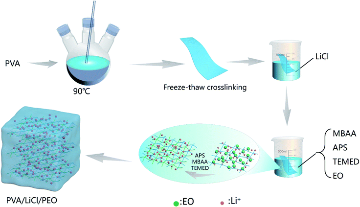
This paper proposes a three-dimensional dual-network interpenetrating structure PVA/LiCl/PEO composite GPE (hereafter referred to as PLE), which allows a flexible metal–air battery to achieve high performance without a traditional auxiliary support. PLE uses water as the solvent to avoid the toxicity and flammability of organic solvents. Polyvinyl alcohol (PVA), containing a large number of hydroxyl groups in its molecular chains, was selected as the main body of the polymer, and the first network was formed via a freeze–thaw method. Then, this was immersed in lithium chloride (LiCl) solution and ethylene oxide (EO) solution. LiCl solution and EO solution diffused into the porous structure. Then, EO is ring-polymerized into polyethylene oxide (PEO) and cross-linked as a second network. This PLE GPE prepared via a simple two-step method combines the common characteristics of a physical gel and a chemical gel, has high ionic conductivity and mechanical strength, and is especially suitable for use in aluminum–air batteries. The discharge voltage of an aluminum–air battery using the PLE GPE is higher than that using liquid electrolyte at the same concentration. The maximum discharge voltage of an assembled single aluminum–air battery can reach 0.73 V. At the same time, to explore the application potential of the PLE GPE in flexible batteries, an aluminum–air flexible battery using PLE was designed, which was discharged in flat, bent, and folded states, respectively. Excellent and stable discharge performance was shown in all cases. Thus, the PLE GPE has broad application prospects for future use.
Experimental
Experimental materials
Polyvinyl alcohol (PVA-1799, degree of alcoholysis: 98–99% (mol mol−1), Aladdin); ethylene oxide (EO, >99.0%, Aladdin); anhydrous lithium chloride (LiCl, AR 99.0%, McLean); sodium ethoxide (C2H5NaO, >99.0%, Mclean); N,N-methylene bisacrylamide (MBAA, AR, McLean), tetramethyl ethylenediamine (TEMED, 99%, Aladdin), ammonium persulfate (APS, AR, 98.5%, Aladdin); absolute ethanol (C2H6O, 99.5%, McLean); manganese dioxide (MnO2, AR, 85%, McLean); superconducting carbon black (McLean); and polyvinylidene fluoride (PVDF, McLean) were all used. The laboratory water (H2O) used in this study is deionized water.Preparation of the gel polymer electrolyte
6 wt%, 8 wt%, and 10 wt% LiCl aqueous solutions were prepared. 8 wt% sodium ethoxide–ethanol solution was prepared. N,N-Methylene bisacrylamide (MBAA), ammonium persulfate (APS), tetramethyl ethylenediamine (TMED), and ethylene oxide (EO) solution were mixed with a relative ethylene oxide molar ratio of 0.1 mol% to prepare mixed EO solution. 15 wt% PVA solution was frozen at −18 °C for 24 h and thawed for 5 h, and this was repeated 4 times; then, PVA was soaked in the 6 wt%, 8 wt%, and 10 wt% LiCl solutions for 10 h and dried at room temperature to obtain PVA/LiCl(6), PVA/LiCl(8), and PVA/LiCl(10) gels. The dried gels were soaked in 8 wt% sodium ethoxide–ethanol for 8 h and dried at room temperature. The obtained dried gels were soaked in the ethylene oxide mixed solution for 24 h, and dried at room temperature to obtain PL6E, PL8E, and PL10E GPEs. In LiCl(x), x is the mass concentration of LiCl.Fabrication of an air cathode and aluminum–air battery
Manganese dioxide, superconducting carbon black, and PVDF were accurately weighed at a mass ratio of 8![[thin space (1/6-em)]](https://www.rsc.org/images/entities/char_2009.gif) :
:![[thin space (1/6-em)]](https://www.rsc.org/images/entities/char_2009.gif) 1
1![[thin space (1/6-em)]](https://www.rsc.org/images/entities/char_2009.gif) :
:![[thin space (1/6-em)]](https://www.rsc.org/images/entities/char_2009.gif) 1, and a catalyst ink was prepared upon mixing. Imitating the approaches of early research, a microporous membrane was used as the current collector to obtain higher flexibility. The catalyst ink was coated on both sides of the microporous membrane to form an air electrode. This was dried in an oven at 45 °C. A single aluminum–air battery with a laminate structure was fabricated with Al foil, the PLE GPE, and the air electrode.
1, and a catalyst ink was prepared upon mixing. Imitating the approaches of early research, a microporous membrane was used as the current collector to obtain higher flexibility. The catalyst ink was coated on both sides of the microporous membrane to form an air electrode. This was dried in an oven at 45 °C. A single aluminum–air battery with a laminate structure was fabricated with Al foil, the PLE GPE, and the air electrode.
The total discharge reaction of the battery is:
| 4Al + 3O2 + 6H2O = 4Al(OH)3 | (1) |
The neutral solution discharge reactions are:
| O2 + 2H2O + 4e → 4OH− | (2) |
| Al + 3OH− − 3e → Al(OH)3 | (3) |
Characterization
Samples were frozen using liquid nitrogen and the morphologies of PLE GPE samples were studied via SEM (ZEISS sigma500). FTIR spectra of PLE GPE samples were recorded using a Nicolet 5700 FTIR spectrophotometer (Nicolet, USA) in the range of 4000–400 cm−1. An electronic universal testing machine was used to measure the tensile strength and tensile modulus values of PLE GPE samples. Small specimen require the use of a traction gauge, and the tensile rate was 10 mm min−1.Electrochemical testing
In this study, the conductivity of the PLE GPE was measured via the AC impedance method. The GPE is sandwiched between two stainless-steel electrodes to assemble a button battery. Chenhua CHI760E apparatus is used for impedance testing, and the test frequency is 0.1–1![[thin space (1/6-em)]](https://www.rsc.org/images/entities/char_2009.gif) 000
000![[thin space (1/6-em)]](https://www.rsc.org/images/entities/char_2009.gif) 000 Hz. When the imaginary part of the impedance of the AC impedance curve is zero, the value of the corresponding real part of the impedance is the bulk resistance R of the electrolyte; then, the conductivity of the GPE can be calculated via the following formula:
000 Hz. When the imaginary part of the impedance of the AC impedance curve is zero, the value of the corresponding real part of the impedance is the bulk resistance R of the electrolyte; then, the conductivity of the GPE can be calculated via the following formula:| σ = L/(RbA) | (4) |
All electrochemical evaluations were carried out using an electrochemical analyzer (RST-5000F). At room temperature, a specific current density (0.5 mA cm−2) was applied to the coin cell and cell voltages were recorded.
Results and discussion
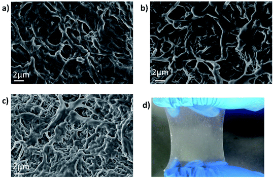
The synthesis procedure of PLE and a digital photo of the material are illustrated in Fig. 1 and 2d, respectively (details in the Experimental section). Fig. 2a–c show SEM images of PL6E, PL8E, and PL10E, respectively. It can be clearly seen from the images that the surface of PLE has a rich pore structure and an intertwined network structure.FTIR spectroscopy was used to characterize the chemical structure of the hydrogel, as shown in Fig. 3a; there are no intermolecular forces between PVA and PEO, so this can be regarded as a simple physical blend. As a result, the infrared spectrum of the two polymers are simply a superposition of the absorption peaks produced by their respective groups. At 3330 cm−1, the absorption peak from –OH stretching vibrations is seen, which illustrates hydrogen-bond association; the peak at 2946 cm−1 arises from the stretching vibrations of –CH3; the C![[double bond, length as m-dash]](https://www.rsc.org/images/entities/char_e001.gif) O stretching band from carboxyl groups appeared at 1640 cm−1 in the PVA, PLx, and PLxE hydrogel spectra; the peak at 1419 cm−1 is from –CH2 bending vibrations; there is a strong absorption peak at 1100 cm−1, which is from vibrational absorption of C–O–C; and the in-plane deformation of –CH2CH2O– in PEO results in a peak at 844 cm−1.
O stretching band from carboxyl groups appeared at 1640 cm−1 in the PVA, PLx, and PLxE hydrogel spectra; the peak at 1419 cm−1 is from –CH2 bending vibrations; there is a strong absorption peak at 1100 cm−1, which is from vibrational absorption of C–O–C; and the in-plane deformation of –CH2CH2O– in PEO results in a peak at 844 cm−1.
 | ||
| Fig. 3 (a) FTIR spectra of PVA, PLx, and PLxE. (b) The stress–strain curves of PL6E, PL8E, and PL10E. (c) Thermogravimetric analysis of PVA, PEO, and PVA/PEO. | ||
The mechanical stability of the GPE composite is important for the stability of the battery structure during the process of battery assembly and cycling. During the cycling process, the volumes of positive and negative electrode materials will expand, which can result in poor interfacial contact between the electrolyte and electrode materials or, potentially, even battery failure. A highly elastic electrolyte can always maintain excellent interfacial contact between the electrolyte and the electrode, improving the cycling stability of the battery. The stress–strain curves of PL6E, PL8E, and PL10E are shown in Fig. 3b. In our test results, PL8E shows the best mechanical properties, with tensile strength of 105.5 MPa and elongation at break of 361.9%. Generally speaking, the elongation at break of PVA hydrogels is about 150% and the tensile stress is 1.0 MPa.16,34 It can be clearly seen from the data that the formation of PEO optimizes the overall mechanical properties of the composite gel electrolyte. This fully illustrates the excellent mechanical properties of the dual-network structure. In the electrolyte salt concentration range of 6–8 wt%, with an increase in the electrolyte salt concentration, the molecular chains curl and become smaller. Li+ is prone to intramolecular cross-linking with the polymer molecules, forming a large number of tight cross-linked polymer coils, thereby improving the overall mechanical properties of the composite GPE. Although the introduction of salt ions is necessary to obtain high conductivity, the hydrogen bonds between polymer chains will be destroyed if the salt concentration is too high.35,36 Therefore, when the electrolyte concentration exceeds 8 wt%, the overall mechanical properties of the composite GPE decrease.
Fig. 3c shows the thermogravimetric curves of PVA, PEO, and the PVA/PEO DN hydrogel. The initial weight loss from all samples below 100 °C was associated with the evaporation of hydrogen-bonded bound water. For the PVA/PEO DN hydrogel, weight loss of about 70% in the range of 250–350 °C should be attributed to the degradation of the polymer sidechains. PVA exhibited the lowest thermal stability of these samples. Comparing the thermal stabilities of the three hydrogels, the DN hydrogel has the highest thermal stability, indicating that the thermal stability of the hydrogel is enhanced upon the introduction of another cross-linked network. In addition, the PVA/PEO DN hydrogel has higher residual mass than the other hydrogels, indicating that the PVA/PEO DN hydrogel has better thermal stability.
An AC impedance spectrum is generally composed of a circular arc and a straight line with a certain slope, representing the high-frequency region and the low-frequency region, respectively. The formation of an arc in the high-frequency region is caused by the movement of lithium ions, generating impedance on the electrode surface layer. In this experiment, both the positive and negative electrodes were made of stainless steel. Because there is no reaction between the stainless-steel electrodes and the electrolyte, the arc originally present in the high-frequency region is close to infinity. Consequently, the region of the AC impedance spectrum relating to conductivity in this study is approximately linear.
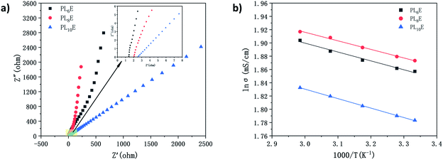
The impedance spectra of PL6E, PL8E, and PL10E are shown in Fig. 4a. Table 2 shows the ionic conductivity values of PL6E, PL8E, and PL10E at room temperature. The highest ionic conductivity is 6.51 × 10⁻³ S cm−1. This is about three times higher than that of a neutral GPE prepared on a single polymer substrate. The ionic conductivity of the GPE is mainly affected by the polymer matrix and the electrolyte salt. In the GPE, lithium ions are coordinated with the oxygen atoms of carbonyl groups, and the ions that are weakly linked to the molecular chain will be separated under the action of an electric field. Cations migrate through the coordination sites of carbonyl oxygen atoms, resulting in ionic conductivity. PVA and PEO contain large numbers of carboxyl groups which can provide coordination sites for oxygen atoms and lithium ions, thus improving the ionic conductivity. When 8 wt% LiCl solution is introduced, PLE exhibits the largest ionic conductivity. Because carbonyl groups can coordinate with lithium ions in a stable manner, the stability of the lithium-ion transmission network structure is ensured. However, when 10 wt% LiCl solution is introduced, the ionic conductivity of PL10E is decreased. This is mainly due to the destruction of the polymer network structure as a result of the high salt concentration, which limits the movement of lithium ions and polymer chains. Therefore, due to interactions between the GPE structure and the electrolyte salt, the electrolyte salt concentration is key to lithium-ion migration, and it greatly influences the ionic conductivity of the electrolyte.
| PL6E | PL8E | PL10E | |
|---|---|---|---|
| Rb (Ω) | 1.34 | 2.04 | 2.56 |
| Thickness (cm) | 0.017 | 0.026 | 0.030 |
| Ionic conductivity (S cm−1) | 6.47 × 10⁻³ | 6.51 × 10⁻³ | 5.95 × 10⁻³ |
Table 3 shows the ionic conductivities of the GPEs at different temperatures, from 25–65 °C. Each GPE shows higher ionic conductivity upon raising the temperature. This is mainly because high temperature promotes the migration of carrier ions.
| σ25 °C (mS cm−1) | σ30 °C (mS cm−1) | σ40 °C (mS cm−1) | σ50 °C (mS cm−1) | σ60 °C (mS cm−1) | |
|---|---|---|---|---|---|
| PL6E | 6.47 | 6.50 | 6.58 | 6.67 | 6.73 |
| PL8E | 6.51 | 6.55 | 6.64 | 6.74 | 6.82 |
| PL10E | 5.95 | 5.99 | 6.08 | 6.17 | 6.25 |
The ion transport model in the GPEs conforms to the Arrhenius equation, which can be expressed as follows:
 | (5) |
Through testing and data fitting, the Ea value of PL8E is found to be the smallest: 12.91 kJ mol−1 (Fig. 4b and Table 4). This is consistent with the ionic conductivity, verifying that PL8E has the highest ionic conductivity and also reflecting that PL8E has the highest ion migration abilities.
| PL6E | PL8E | PL10E | |
|---|---|---|---|
| Ea (kJ mol−1) | 13.37 | 12.91 | 14.27 |
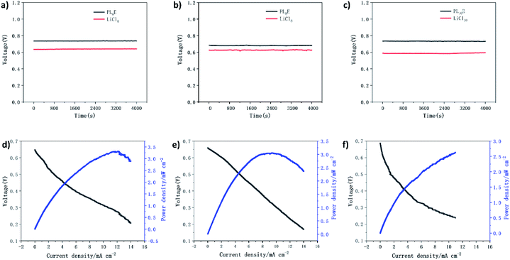
The PLE GPE and liquid electrolyte are assembled into a coin-type aluminum–air battery. Fig. 5a–c shows the discharge performances of the PLE GPE and a liquid electrolyte in an aluminum–air battery. The results show that at a current density of 0.5 mA cm−2 and the same LiCl concentration, the discharge voltage of the aluminum–air battery using the PLE GPE is higher than that using liquid electrolyte at the same concentration. The maximum discharge voltage of an assembled single aluminum–air battery can reach 0.73 V, and the calculated Al specific capacity was as high as 735.2 mA h g−1.
Fig. 5d–f shows the battery polarization and power density curves of coin cells with PL6E, PL8E, and PL10E as electrolytes. The applied discharge current density is in the range of 0–14 mA cm−2, between 0.1 V and 0.7 V. With an increase in the current density, the discharge voltage decreases accordingly. PL6E, PL8E, and PL10E act as diaphragms and electrolytes in aluminum–air coin cells, and peak power densities (Pmax) of 3.31, 3.0, and 2.7 mW cm−2 are obtained, respectively. This is because the polymer electrolyte can greatly delay the self-corrosion of the electrode, so the battery has a higher power density as a whole. The coin cell with PL6E as the electrolyte shows the highest power density. This indicates that the PLE GPE can be used as the electrolyte and separator in aluminum–air button batteries.
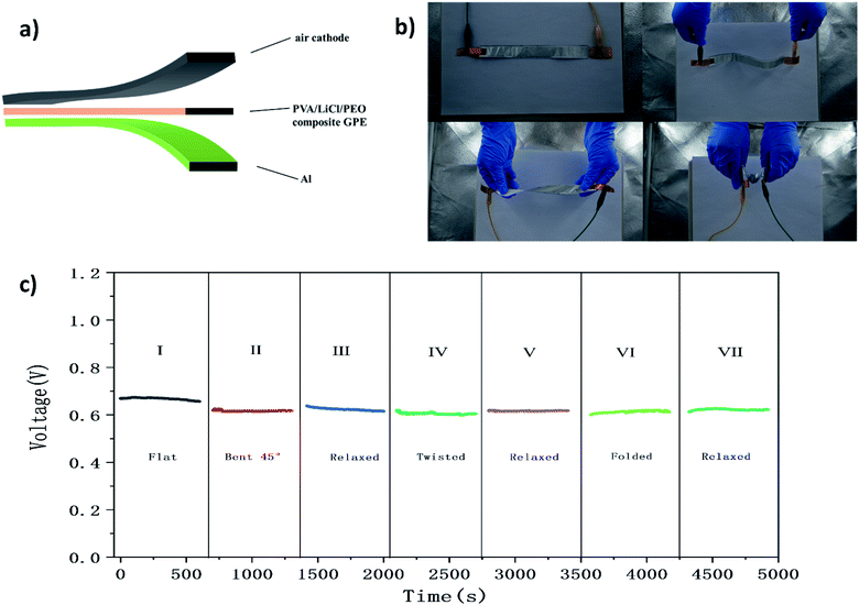
To demonstrate the excellent flexibility of a single aluminum–air battery, the overall performances of batteries were evaluated in response to various types of mechanical deformation (Fig. 6c). As shown in Fig. 6c, a single aluminum–air battery was changed from a flat configuration to bent and twisted states at 0.5 mA cm−2, and the output voltage remains above 92%. The battery was first studied under flat conditions (region I), and the output voltage is maintained at 0.66 V. Then the battery is bent to 45° and cycled in a static bent state (region II) and a relaxed state (region III). Obviously, bending does not affect the performance of the battery. After bending, the output voltage is maintained at 0.61 V. After cycling in a bent state (region II), the battery was returned to a relaxed state (region III), and the voltage recovered to more than 99% of its initial value. The battery is twisted (region IV) and cycled in a static twisted state. Similarly, no significant decay was observed. Once it was returned to a relaxed configuration (region V), the output voltage recovered rapidly. In addition, the battery retained about 99% of its initial voltage after 500 cycles in a folded state (region VI). The excellent cycling performance shows that the static deformation does not affect the cycling performance. The safety of the battery, the generation of a stable output under short-term stress, and the long-term performance are very important for practical applications. The experimental results fully illustrate that an aluminum–air battery with a PLE GPE has the flexibility required to make it suitable for use in flexible electronic equipment.
Conclusions
In summary, a PLE GPE was successfully prepared via a simple two-step method involving freeze–thaw crosslinking and chemical crosslinking. It is found that when the mass fraction of PVA is 15% and the mass fraction of LiCl is 8%, the composite gel electrolyte shows the best performance index values, and the tensile strength, elongation at break, and ionic conductivity reach 105.5 MPa, 361.9%, and 6.51 × 10⁻³ S cm−1, respectively. At a current density of 0.5 mA cm−2 and the same LiCl concentration, the discharge voltage of an aluminum–air battery using the PLE GPE is higher than that using liquid electrolyte, and the Al specific capacity was as high as 735.2 mA h g−1. When a single flexible aluminum–air battery was changed from a flat state to bent and twisted states at 0.5 mA cm−2, the output voltage remained above 92%. When the battery was returned to the relaxed state, the voltage recovered to more than 99% of its initial value, and the battery voltage remained at about 99% of its initial value after 500 cycles in a folded state. In addition, the GPE can be used as both a separator and electrolyte, which can greatly reduce the irreversible corrosion of the anode and prolong the service life of the battery. In light of the above characteristics, the PLE GPE, with high transparency, high conductivity, high stretchability, and good safety, has broad application prospects in wearable electronic devices, especially in aluminum–air batteries. It overcomes the limitations of the traditional rigid structures of aluminum–air batteries. The PLE GPE prepared with the method described in this paper exhibits excellent performance, making it a promising candidate for potential applications in flexible electronics, wearable devices, artificial skin, soft robotics, energy storage, and sensors.Conflicts of interest
There are no conflicts to declare.Acknowledgements
This work was supported by the Xi'an Science and Technology Plan Project, China (2019218214GXRC018CG019-GXYD18.8), Natural Science Project of Shaanxi Provincial Department of Education (No. 20JK0927), Xi'an Science and Technology Plan Project, China (2019220914SYS024CG046), Xi'an Key Laboratory of Energy Recycling and Storage Materials, and Earth Engineering Center and Center for Advanced Materials for Energy and Environment at Columbia University.Notes and references
- S. Wu, Q. Zhang, J. Ma, D. Sun and H. Wang, Mater. Today Energy, 2020, 100499 CrossRef.
- Y. Liu, Q. Sun, X. Yang, J. Liang, B. Wang, A. Koo, R. Li, J. Li and X. Sun, ACS Appl. Mater. Interfaces, 2018, 10, 19730–19738 CrossRef CAS PubMed.
- P. Sun, J. Chen, Y. Huang, J.-H. Tian, S. Li, G. Wang, Q. Zhang, Z. Tian and L. Zhang, Energy Storage Mater., 2021, 34, 427–435 CrossRef.
- R. Mori, RSC Adv., 2017, 7, 6389–6395 RSC.
- G. A. Elia, K. V. Kravchyk, M. V. Kovalenko, J. Chacón, A. Holland and R. G. A. Wills, J. Power Sources, 2021, 481, 228870 CrossRef CAS.
- L. S. Tao, T. Kurokawa, S. Kuroda, A. B. Ihsan, T. Akasaki, K. Sato, M. A. Haque, T. Nakajima and P. G. Jian, Nat. Mater., 2013, 12, 932–937 CrossRef PubMed.
- S. Chang, B. Wang, Y. Liu, Z. Li, X. Hu, X. Zhang and H. Zhang, Polymer, 2020, 188, 122156 CrossRef CAS.
- J. M. Abisharani, S. Balamurugan, A. Thomas, S. Devikala, M. Arthanareeswari, S. Ganesan and M. Prakash, Sol. Energy, 2021, 218, 552–562 CrossRef CAS.
- H. S. Jang, J. C. Raj, W. G. Lee, B. C. Kim and K. H. Yu, RSC Adv., 2016, 6, 75376–75383 RSC.
- G. Ma, J. Li, K. Sun, H. Peng, J. Mu and Z. Lei, J. Power Sources, 2014, 256, 281–287 CrossRef CAS.
- X. Wang, Z. Liu, Y. Tang, J. Chen, Z. Mao and D. Wang, Solid State Ionics, 2021, 359, 115532 CrossRef CAS.
- K. M. Abraham, H. S. Choe and D. M. Pasquariello, Electrochim. Acta, 1998, 43, 2399–2412 CrossRef CAS.
- T. S. Tiong, M. H. Buraidah, L. P. Teo and A. K. Arof, Ionics, 2016, 22, 2133–2142 CrossRef CAS.
- X. Peng, Y. Zhu, S. Song, X. Zhang and Y. Xiang, J. Power Sources, 2020, 455, 227963 CrossRef CAS.
- P. Xu, H. Chen, X. Zhou and H. Xiang, J. Membr. Sci., 2021, 617, 118660 CrossRef CAS.
- X. Hu, L. Fan, G. Qin, Z. Shen, J. Chen, M. Wang, J. Yang and Q. Chen, J. Power Sources, 2019, 414, 201–209 CrossRef CAS.
- H. Peng, Y. Lv, G. Wei, J. Zhou, X. Gao, K. Sun, G. Ma and Z. Lei, J. Power Sources, 2019, 431, 210–219 CrossRef CAS.
- H. Zhang, W. Niu and S. Zhang, Chem. Eng. J., 2020, 387, 124105 CrossRef CAS.
- K. Zhang, R. Simic and N. D. Spencer, Biotribology, 2021, 26, 100161 CrossRef.
- N. Yuan, L. Xu, H. Wang, Y. Fu, Z. Zhang, L. Liu, C. Wang, J. Zhao and J. Rong, ACS Appl. Mater. Interfaces, 2016, 8, 34034–34044 CrossRef CAS PubMed.
- L. Jay, K. Kanda, P. Kapsa, H. Zahouani and K. Adachi, Wear, 2021, 484–485, 203725 CrossRef CAS.
- S. K. Kim, H. J. Koo, J. Liu and P. V. Braun, ACS Appl. Mater. Interfaces, 2017, 19925–19933 CrossRef CAS PubMed.
- M. Jiang, J. Zhu, C. Chen, Y. Lu, Y. Ge and X. Zhang, ACS Appl. Mater. Interfaces, 2016, 8, 3473–3481 CrossRef CAS PubMed.
- M. A. Hashim and A. S. A. Khiar, Mater. Res. Innovations, 2011, 15, s63–s66 CrossRef.
- F. F. Hatta, M. Z. A. Yahya, A. M. M. Ali, R. H. Y. Subban, M. K. Harun and A. A. Mohamad, Ionics, 2005, 11, 418–422 CrossRef CAS.
- J. Xi, X. Qiu, L. Jian, X. Tang, W. Zhu and L. Chen, J. Power Sources, 2006, 157, 501–506 CrossRef CAS.
- S. Klongkan and J. Pumchusak, Electrochim. Acta, 2015, 161, 171–176 CrossRef CAS.
- P. Pal and A. Ghosh, Electrochim. Acta, 2018, 278, 137–148 CrossRef CAS.
- P. Michał, G.-C. Oihane, O. Uxue and M. L. d. Juan, Electrochim. Acta, 2017, 255, 48–54 CrossRef.
- J. He, J. Liu, J. Li, Y. Lai and X. Wu, Mater. Lett., 2016, 170, 126–129 CrossRef CAS.
- Y. M. C. D. Jayathilake, K. S. Perera, K. P. Vidanapathirana and L. R. A. K. Bandara, Sri Lankan J. Phys., 2014, 15, 11–17 CrossRef.
- Q. Tang, H. Li, Y. Yue, Q. Zhang, H. Wang, Y. Li and P. Chen, Mater. Des., 2017, 118, 279–285 CrossRef CAS.
- R. Muchakayala, S. Song, J. Wang, Y. Fan and M. Bengeppagari, J. Ind. Eng. Chem., 2018, 59, 79–89 CrossRef CAS.
- T. Ye, Y. Zou, W. Xu, T. Zhan, J. Sun, Y. Xia, X. Zhang and D. Yang, J. Power Sources, 2020, 475, 228688 CrossRef CAS.
- H. Charaya, X. Li, N. Jen and H. J. Chung, Langmuir, 2019, 35, 1526–1533 CrossRef CAS PubMed.
- A. Bhattacharya and P. Ray, J. Appl. Polym. Sci., 2004, 93, 122–130 CrossRef CAS.
| This journal is © The Royal Society of Chemistry 2021 |

