
 Open Access Article
 This Open Access Article is licensed under a Creative Commons Attribution-Non Commercial 3.0 Unported Licence
Enhanced storage behavior of quasi-solid-state aluminum–selenium battery
Haiping Lei *ab,
Suqin Lib and
Jiguo Tua
*ab,
Suqin Lib and
Jiguo Tua
aState Key Laboratory of Advanced Metallurgy, University of Science and Technology Beijing, Beijing 100083, PR China. E-mail: leihaiping0214@ustb.edu.cn
bSchool of Metallurgical and Ecological Engineering, University of Science and Technology Beijing, Beijing 100083, PR China
First published on 13th December 2021
Abstract
The current aluminum batteries with selenium positive electrodes have been suffering from dramatic capacity loss owing to the dissolution of Se2Cl2 products on the Se positive electrodes in the ionic liquid electrolyte. For addressing this critical issue and achieving better electrochemical performances of rechargeable aluminum–selenium batteries, here a gel-polymer electrolyte which has a stable and strongly integrated electrode/electrolyte interface was adopted. Quite intriguingly, such a gel-polymer electrolyte enables the solid-state aluminum–selenium battery to present a lower self-discharge and obvious discharging platforms. Meanwhile, the discharge capacity of the aluminum–selenium battery with a gel-polymer electrolyte is initially 386 mA h g−1 (267 mA h g−1 in ionic liquid electrolyte), which attenuates to 79 mA h g−1 (32 mA h g−1 in ionic liquid electrolyte) after 100 cycles at a current density of 200 mA g−1. The results suggest that the employment of a gel-polymer electrolyte can provide an effective route to improve the performance of aluminum–selenium batteries in the first few cycles.
1. Introduction
Due to its abundant natural resources, high theoretical capacity (2980 mA h g−1)/volumetric energy density (8046 mA h cm−3), high safety and nontoxicity, aluminum has been used as a negative material in rechargeable aluminum-ion battery (AIB) which is regarded as a potential candidate for alleviating partial resource shortages in lithium-ion batteries.1–4 Up to date, one of the most essential challenges in AIB is the lack of appropriate high energy density positive electrode materials.5,6 Among the potential candidates, although selenium has a lower theoretical gravimetric capacity (1357 mA h g−1) comparing with the congener of sulfur (1675 mA h g−1), it has similar chemical properties but higher electronic conductivity and theoretical volumetric capacity density.7–11 However, as reported in the previous work, the formed Se2Cl2 intermediate product during charging/discharging processes in aluminum–selenium (Al–Se) battery is highly soluble in ionic liquid electrolyte (ILE) and easily shuttles to the aluminum (Al) negative electrode, which will lead to the loss of the active materials, collapse of electrode interfacial and serious attenuation of Al–Se battery's capacity.7–13Solid-state electrolytes have been studied extensively in lithium-ion batteries and sodium-ion batteries with high safety, high energy density, and low self-discharge, which can provide a promising choice to the next generation of efficient storage devices.14–17 Meanwhile, the solid-state electrolyte doesn't have good fluidity, which may play a role in relieving the dissolution of intermediate products. Furthermore, solid-state electrolyte can act as a conducting ion and a separator, which can simplify the assembly of battery and reduce the cost. As a rational substitute for the conventional ILE, the use of solid-state electrolytes has been recognized as one of the most promising routes to addressing the solubility issue of Se2Cl2 in Al–Se batteries. Solid-state electrolytes can be divided into three main categories: gel-polymer solid electrolytes, composite polymer electrolytes and inorganic solid electrolytes.18 The gel-polymer electrolyte (GPE) presents a stable and safe electrode/electrolyte interface, which can enhance the cycling stability and rate performance of the battery.19–21
From the perspective of controlling the dissolution and migration of intermediate product Se2Cl2 in ILE, the GPE with stable and strongly integrated electrode/electrolyte interface was employed in this work to study the effects on the dynamics, specific capacity, and cycling stability of Al–Se battery. After using GPE, Al–Se battery presents a lower self-discharge and obvious discharging platforms. Meanwhile, the first discharge capacity of Al–Se battery increases to 386 mA h g−1 at the current density of 200 mA g−1. The GPE can effectively inhibit the Se2Cl2 diffusion and retain a strongly integrated electrolyte/electrode structure. These remarkable performances can be ascribed to the immobilization of Se2Cl2 imparted by GPE and the construction of a robust integrated GPE/electrode interface.
2. Experimental section
Materials
Al foil (99.99%) was purchased from Research Institute for Nonferrous Metals (Beijing, P. R. China). Tantalum foil (Ta, 99.9%) and molybdenum foil (Mo, 99.0%) were obtained from Sheng Yuan Metal Co. Ltd. SeO2 (99%, Aladdin), poly-cyclodextrin (98.0%, Aladdin), ascorbic acid (99.5%, Aladdin), acrylamide (98.5%, Alfa Aesar), dichloromethane (DCM, ≥99%, Alfa Aesar), 1-ethyl-3-methylimidazolium chloride ([EMIm]Cl, 97%, Acros Chemicals), polyvinylidene difluoride binder (PVDF, Macklin), N-methyl-2-pyrrolidinone (NMP, ≥99.0%, Acros Chemicals), anhydrous aluminum chloride (AlCl3, 99.999%, Sigma Aldrich), and 2,2′-azodiisobutyronitrile (AIBN, >98%, TCI) were purchased from commercial sources.Materials preparation
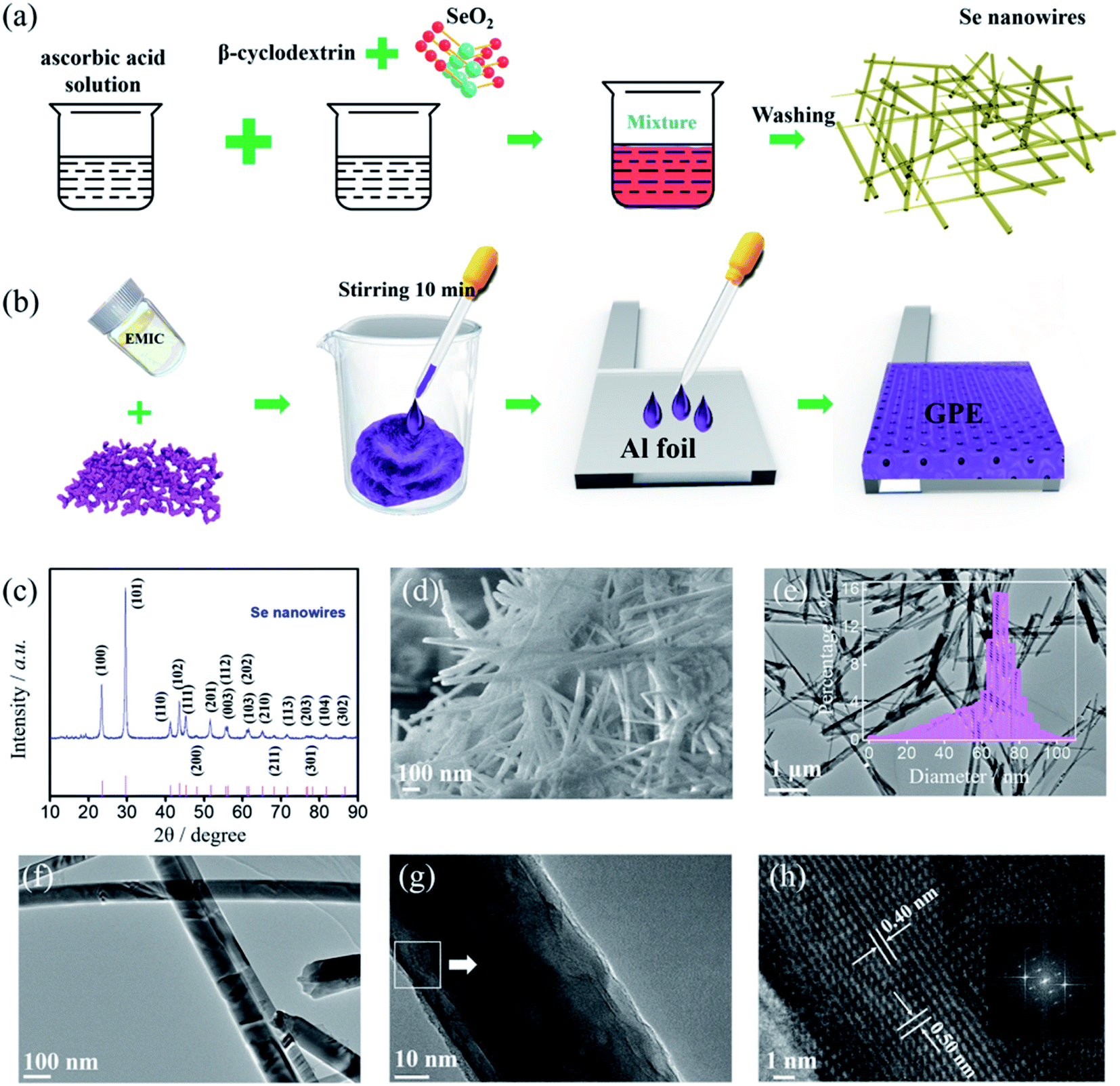 | ||
| Fig. 1 (a) Schematic diagram of the preparation of selenium nanowires. (b) Schematic diagram of the preparation of the GPE. (c) XRD pattern of as-prepared selenium nanowires. (d) FESEM images of selenium nanowires. (e and f) TEM images of selenium nanowires. Inset: the histogram of Se nanowires diameter. (g and h) HRTEM images of selenium nanowires. | ||
Al foil (thickness of 50 μm), Ta foil (thickness of 10 μm) and Mo foil (thickness of 20 μm) were prepared and cleaned in ethanol by ultrasound (KQ2200E, 40 kHz). The positive electrodes were prepared by 60 wt% of treated selenium nanowire, 30 wt% of acetylene black, and 10 wt% of PVDF in NMP, and casted onto a Ta foil current collector after fully stirring. Then Mo foil was attached to Ta foil by conducting tape after drying.
Assembling the soft-package Al–Se battery with ILE (Se/ILE/Al battery)
Room temperature ILE was made by mixing [EMIm]Cl and AlCl3 in an argon-atmosphere glove box ([O2] < 0.1 ppm, [H2O] < 0.1 ppm), and AlCl3 was slowly dissolved in [EMIm]Cl with the molar ratio 1.3![[thin space (1/6-em)]](https://www.rsc.org/images/entities/char_2009.gif) :1. The resulting light-yellow and transparent liquid was stirred at room temperature for 30 min. And then the ([EMIm]AlxCly) ionic liquid electrolytes were standing at least 12 h before used. Positive electrode, Al foil negative electrode, glass fiber (GF/A, Whatman) separator, and Al-plastic film were assembled, injected electrolyte and sealed in an Ar-filled glove box.
:1. The resulting light-yellow and transparent liquid was stirred at room temperature for 30 min. And then the ([EMIm]AlxCly) ionic liquid electrolytes were standing at least 12 h before used. Positive electrode, Al foil negative electrode, glass fiber (GF/A, Whatman) separator, and Al-plastic film were assembled, injected electrolyte and sealed in an Ar-filled glove box.
Assembling the soft-package Al–Se battery with GPE (Se/GPE/Al battery)
GPE was prepared by in situ gelation method in an argon-atmosphere glove box as shown in Fig. 1(b).20 First, AlCl3 (1.34 g) and acrylamide (0.7 g) were slowly dissolved in methylene chloride (12 g) under vigorous stirring until the solution turned light yellow to achieve complexation of acrylamide and AlCl3. Then, as-prepared 1.5 mol ratio of [EMIm]AlxCly electrolyte (8 g) was added into the solution. Subsequently, the polymerization process started after adding the initiator AIBN (0.007 g). Finally, the solution was casting onto Al foil until the mixing appeared partially solidified state and the sample was placed in the glove box for 12 h to get the GPE membrane. The quasi-solid-state Al–Se battery were fabricated with the coated positive electrode and the GPE membrane formed on the Al foil negative electrode, followed by assembling them into a Al-plastic film and sealing with a heat sealing machine (BLEUETS FR-300B, sealing temperature below 300 °C) in an Ar-filled glove box.Electrochemical tests
CV measurements were performed at scan rates of 1, 5, 10 mV s−1 over voltage range of 0.01 to 2.3 V versus Al/Al3+ by a CHI 660E (Shanghai, China) electrochemical workstation in two-electrode mode. Galvanostatic charge/discharge tests were carried out at current densities of 200, 400, 600 mA g−1 with the potential window of 0.01 to 2.2 V at room temperature using Neware BTS-53 tester. Electrochemical impedance spectroscopy measurements (CHI 660E) were conducted at fresh, charged and discharge cycled cells in the frequency range from 100 kHz to 0.01 Hz. Self-discharge (Neware BTS-53) was performed by resting for 6 h and different voltage.Characterization
Field emission scanning electron microscopy (FESEM) were taken to determine the morphology and composition contents of the original materials and cycled materials on a JEOL JSM-6701F. High-resolution transmission electron microscopy (HRTEM) analyses were conducted on a JEOL JEM-2010. The phase structures of the original materials were obtained from X-ray diffraction (XRD, Rigaku, D/max-RB) with a Cu Kα wave.3. Results and discussion
The synthesis procedure of selenium nanowires is schematically shown in Fig. 1(a). Under the facile two-step operation, the as-prepared selenium nanowires were obtained. In order to characterize the crystallinity and phase of as prepared selenium nanowires, the synthesized materials were tested by XRD. From Fig. 1(c), all the reflections could be assigned to a pure hexagonal phase of selenium (JCPDS card no. 06-0362) with lattice parameters of a = 4.3662 Å and c = 4.9536 Å.22–26 No residual phase is detected, indicating that the successful preparation of selenium products with high crystallinity and purity.Fig. 1(d–h) shows the morphology of as-prepared selenium samples by FESEM and TEM. The FESEM image (Fig. 1(d)) reveals the obtained products have the wire structure and are in large scale with uniform size and smooth shape, which are typical one-dimensional wire materials. Meanwhile, as can be seen from the TEM images amplified in Fig. 1(e) and (f), the nanowires have relatively uniform diameter and smooth surfaces. The diameter distribution of Se nanowires is presented in Fig. 1(e), suggests the uniform diameter size is about 70 nm. The HRTEM image in Fig. 1(h) shows the lattice fringes of Se nanowire are arranged in parallel. Meanwhile, the clear lattice fringes with d-spacing of ∼0.4 nm and 0.5 nm correspond to the (100) and (001) lattice planes of hexagonal phase Se, revealing that the nanowire was single crystalline.27–29 The inset describes a fast Fourier transform (FFT) of the image of Fig. 1(h) which is equivalent to an electron diffraction pattern. The HRTEM image and FFT pattern demonstrate that the nanowire has a preferential orientation along the (001) direction.29
The Al–Se battery was fabricated with synthesized well-defined nanostructure selenium nanowires as the positive electrode, Al foil as the negative electrode, and GPE or ILE as the electrolyte. Obviously, the selenium nanowires have been agglomerated by the PVDF binder and the morphology of selenium nanowires on the positive electrode before cycling can be clearly observed in Fig. 2(a). GPE has certain mechanical strength, can be used as a block between the positive electrode and negative electrode which means the battery with GPE doesn't need GF/A separator. The open circuit potential of the untested battery was detected and it was found that the open circuit potentials of the GPE and ILE battery were both about 1.5 V as shown in Fig. 2(b) and (c).
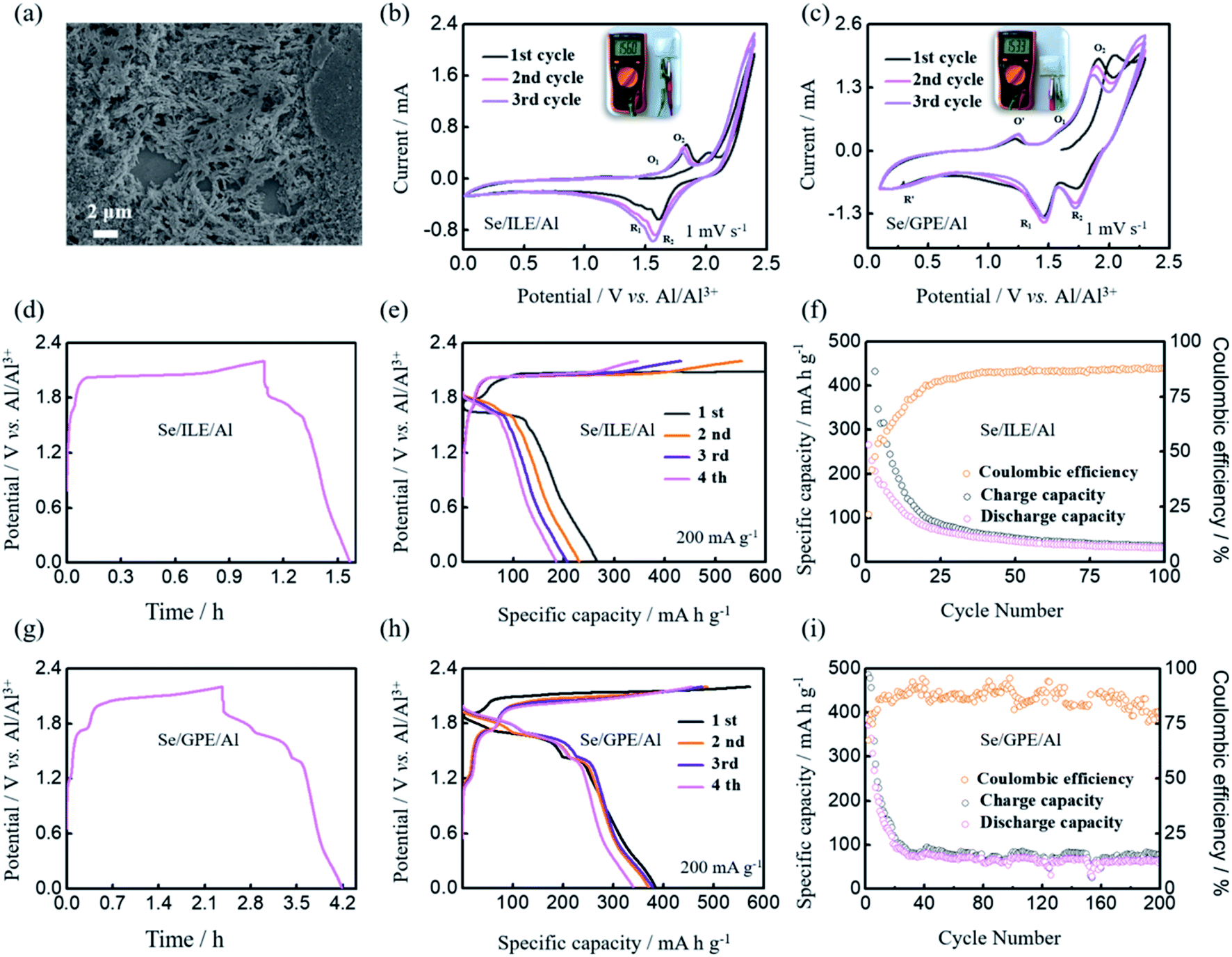 | ||
| Fig. 2 (a) FESEM image of positive electrode before cycling. (b and c) The initial three CV curves at a scan rate of 1 mV s−1 of Al–Se batteries with ILE and GPE. (d and g) The charge/discharge profiles of Al–Se batteries with ILE and GPE. (e and h) The charge/discharge curves at 200 mA g−1 of Al–Se batteries with ILE and GPE. (f and i) The corresponding cycling performance and coulombic efficiency with ILE and GPE. | ||
The typical CV measurements of Al–Se batteries with ILE and GPE in the voltage range of 0.01–2.3 V were carried out at a scan rate of 1 mV s−1, as shown in Fig. 2(b) and (c). The CV curves of Se/ILE/Al battery displays the obvious reduction peaks (∼1.52 and 1.65 V) and the corresponding oxidation peaks (∼1.53 and 1.85 V). The charging and discharge platforms of Al–Se battery are higher than Al–S battery's (charging platform of ∼1.25 V, and discharge platform of ∼0.75 V),30–32 Al–CuO battery's (charging platform of ∼0.8 V, and discharge platform of ∼0.6 V),33 and Al–CuS@C battery (charging platform of ∼1.5 V, and discharge platform of ∼1.0 and 0.4 V).34 Meanwhile, they are similar with the Al–Te battery's (charging platform of ∼1.6 and 1.8 V, discharge platform of ∼1.5 and 0.45 V).35,36 Therefore, Se as the positive electrode material of AIB is competitive, even though the non-overlapping CV curves with cycling may be caused by the loss of reactants dissolved in the ILE. For the Se/GPE/Al battery, the reduction peaks shift to 1.73 and 1.47 V, the oxidation peaks shift to higher potentials (1.59 and 1.91 V). In addition, the peak current densities of the Se/GPE/Al battery are obviously higher than those of Se/ILE/Al battery. What's more, almost overlapped CV curves are observed from the second cycle, indicating the good reversibility of Se electrode in Se/GPE/Al battery. An additional pair of oxidation–reduction peaks were appeared with the reduction peak at 0.32 V and the oxidation peak at 1.24 V, probably caused by the side reaction of GPE.
Meanwhile, further galvanostatic charge and discharge tests were implemented at the current density of 200 mA g−1 to assess the energy storage capacity of the Al–Se batteries with ILE and GPE, as shown in Fig. 2(d–i). The typical charge/discharge curves are shown in Fig. 2(d) and (g), which shows the obvious charging platforms (∼1.67 and 2.0 V of Se/ILE/Al battery, ∼1.21, 1.69 and 2.0 V of Se/GPE/Al battery) and discharge platforms (∼1.60 and 1.78 V of Se/ILE/Al battery, ∼1.85, 1.65 and 1.39 V of Se/GPE/Al battery). Se/GPE/Al battery exhibits one more pair and more obvious charging and discharging platforms than Se/ILE/Al battery. It is clear that the Se/GPE/Al battery exhibits nearly the same initial specific charge capacity (571 mA h g−1) comparing with the Se/ILE/Al battery's (594 mA h g−1) at the current density of 200 mA g−1 (Fig. 2(e) and (h)). The 1st, 2nd, 3rd, and 4th discharge capacities of the Se/GPE/Al battery at 200 mA g−1 are 386, 371, 378, and 340 mA h g−1, respectively, while the corresponding capacities of the Se/ILE/Al battery are only 267, 232, 206, and 184 mA h g−1, respectively. The charge/discharge behaviors are in good agreement with the CV measurements in Fig. 2(c). Se/ILE/Al battery exhibits a discharge capacity of 32 mA h g−1 over 100 cycles (Fig. 2(f)). In contrast, Se/GPE/Al battery delivers a higher discharge capacity of 79 mA h g−1 over 100 cycles (Fig. 2(i)) comparing with Se/ILE/Al battery. Interestingly, the Se/GPE/Al battery shows a much higher rate performance and better reversibility than the Se/ILE/Al battery. To understand the kinetics of the Al–Se batteries with different electrolyte deeply, CV curves were further investigated at the scan rates of 1, 5 and 10 mV s−1 (Fig. 3(a) and (b)). It is found that the peak current intensities of redox peaks are gradually enhanced with the increase of scanning rate. The oxidation peak voltage is offset to the positive direction, and the reduction peak voltage is offset to the negative direction, further indicating the existence of electrode polarization phenomenon of Al–Se battery. The charge/discharge profiles of Se/ILE/Al and Se/GPE/Al battery at different current densities are presented in Fig. 3(c) and (d). The specific discharge capacities of the Se/GPE/Al battery at the current densities of 400, 600 mA g−1 are 233, 159 mA h g−1, respectively, while the corresponding capacities of Se/ILE/Al battery are only 135, 72 mA h g−1, reflecting that the Se/GPE/Al battery is robust and highly stable.
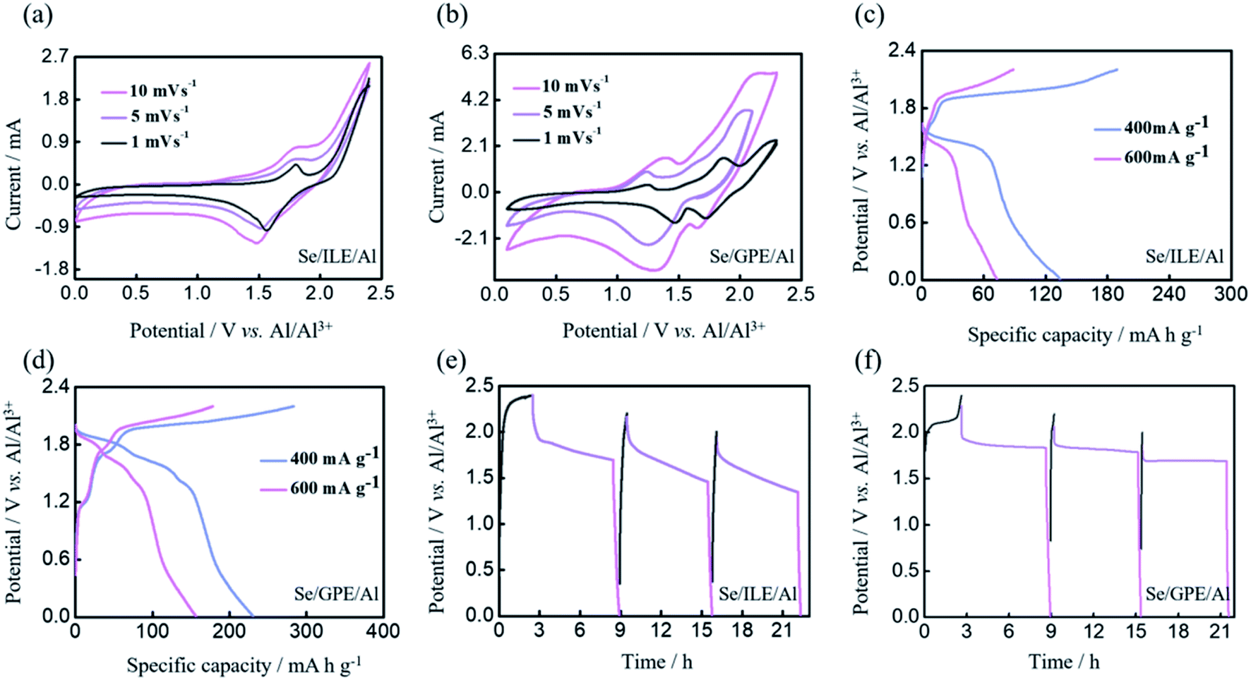 | ||
| Fig. 3 (a and b) The CV curves at scan rates of 1, 5, 10 mV s−1 of Al–Se batteries with ILE and GPE. (c and d) The charge/discharge curves at 400 and 600 mA g−1 of Al–Se batteries with ILE and GPE. (e and f) The self-discharge behaviors of Al–Se batteries with ILE and GPE under different charge potentials. | ||
Fig. 3(e) and (f) shows the self-discharge behaviors of Al–Se battery with ILE and GPE which the batteries were rested for 6 h after charging to 2.0, 2.2, and 2.4 V. The noticeable voltage variation at different charging voltages indicates that the higher charging voltage of Al–Se battery is, the more obvious voltage drop will be. Meanwhile, the voltage of Se/GPE/Al battery firstly falls fast, and then remains at about 1.83, 1.76, and 1.67 V, respectively, which are much higher than the voltages of Se/ILE/Al battery (1.69, 1.50 and 1.36 V, respectively), further implying more stable Se/GPE/Al battery. However, comparing these with commercial lithium-ion batteries,37 the self-discharge of Al–Se battery is still high. Self-discharge behavior may be caused by irreversible side reactions in the battery, including the reactant dissolved in electrolyte, and side reaction of impurities in electrolyte.
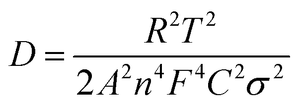
Electrochemical impedance spectroscopy (EIS) was investigated as shown in Fig. 4 to evaluate the interfacial resistance of Al–Se batteries using ILE and GPE electrolyte. Nyquist plots of Se/ILE/Al battery and Se/GPE/Al battery at the different charging states (pristine, fully charged, and fully discharged) are composed of a depressed semicircle corresponding to the charge transfer resistance in the high-to-medium frequency region and a sloping line relating to the ion diffusion ability within the electrodes in the low frequency region as shown in Fig. 4(a) and (c), and the corresponding enlargement curves were shown in Fig. 4(b) and (d). It is seen that the interfacial resistance (Rf) in the Se/ILE/Al battery increases from 1.86 Ω to 3 Ω (charging) and 2.4 Ω (discharging), and the corresponding charge transfer resistance (Rct) rises from 28.8 Ω to 39.4 Ω (charging) and 32.9 Ω (discharging). The Rf in the Se/GPE/Al battery increases from 15.8 Ω to 23.1 Ω (charging) and 20.7 Ω (discharging), and the corresponding charge transfer resistance (Rct) increases from 10.5 Ω to 11.5 Ω (charging) and 23.7 Ω (discharging). The higher Rf of GPE than that of ILE may be due to its poor fluidity. The relationship between the real part of impedance (Z′) and the angular frequency (ω−1/2, in the low frequency region) are shown in Fig. 4(e) and (f). The ion diffusion coefficient (D) can be calculated from the formula as following:38,39
 | (1) |
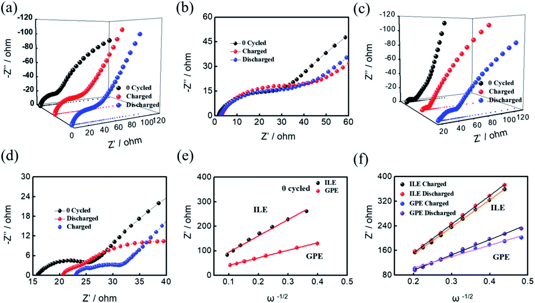 | ||
| Fig. 4 (a and b) Electrochemical impedance spectroscopy of Al–Se battery with ILE at different conditions as marked. (c and d) Electrochemical impedance spectroscopy of Al–Se battery with GPE at different conditions as marked. (e) Relationships of Z′ versus ω−1/2 for Al–Se batteries with ILE and GPE before cycling. (f) Relationships of Z′ versus ω−1/2 for Al–Se batteries with ILE and GPE after cycling. | ||
The morphology of the 50th cycled GPE was characterized by FESEM as shown in Fig. 5(a) and (b), exhibiting the unsmooth but coarse, irregular feature on the electrolyte surface. The GPE skeleton structure is obvious, which has a certain mechanical toughness. After cycling, a lot of gullies appear in the GPE. Inset of Fig. 5(a) is the corresponding EDS spectrum, revealing the Al, Cl and O elements existing. The O element exists in the aluminum hydroxide which was produced by the electrolyte hydrolyzing during the preparation of FESEM samples. The EDS mapping of Al and Cl elements on the surface of the electrolyte are shown in Fig. 5(c) and (d), further conforming that the main ingredients are Al and Cl in the electrolyte after cycled. These results confirm the successfully construction of a robust integrated GPE/selenium positive electrode interface.
 | ||
| Fig. 5 (a and b) FESEM images of the 50th cycled GPE. Inset: the corresponding EDS spectrum of cycled GPE. (c and d) EDS mapping images of Al and Cl of the 50th cycled GPE. | ||
The optical images of cycled Al–Se batteries with different electrolytes are shown in Fig. 6(a), which is evident that the positive materials battery has been dissolved in ILE but not obvious in GPE. Fig. 6(b) shows the FESEM image of cycled positive electrode of Al–Se battery after 50th cycled with ILE. The morphology of selenium nanowires is no longer visible, and obvious cracks and holes are appeared, demonstrating the dissolved behavior of selenium nanowires after cycling in ILE. Fig. 6(c) shows FESEM image of the 50th cycled positive electrode of Al–Se battery with GPE. It is also found that there are many cracks, holes and no obvious selenium nanowires. Fig. 6(d) shows the FESEM and corresponding EDS mapping images, revealing the distribution of Al, Cl, C, Pt, and Se in cycled positive electrode after 50th cycling in ILE. The obvious minor peak between Se and Cl is the element Pt which was sputtered on the surface of the samples for an additional conductive thin layer before the FESEM test. The contents of Al, Cl, C, and Se measured in EDS spectrum are approximately 0.82 wt%, 8.68 wt%, 88.33 wt%, and 2.17 wt% after removing the element Pt, respectively. The FESEM and corresponding EDS mapping images of Al, Cl, C, and Se of 50th cycled positive electrode in GPE as shown in Fig. 6(e), demonstrating no obvious difference with those in ILE. The EDS spectrum reveals the contents of Al, Cl, C, and Se are approximately 0.78 wt%, 6.43 wt%, 90.68 wt%, and 2.12 wt% after removing the element Pt, respectively. These indicate that although GPE can greatly improve the battery performance, the selenium nanowires still cannot avoid being completely dissolved in GPE after 50th cycling process.
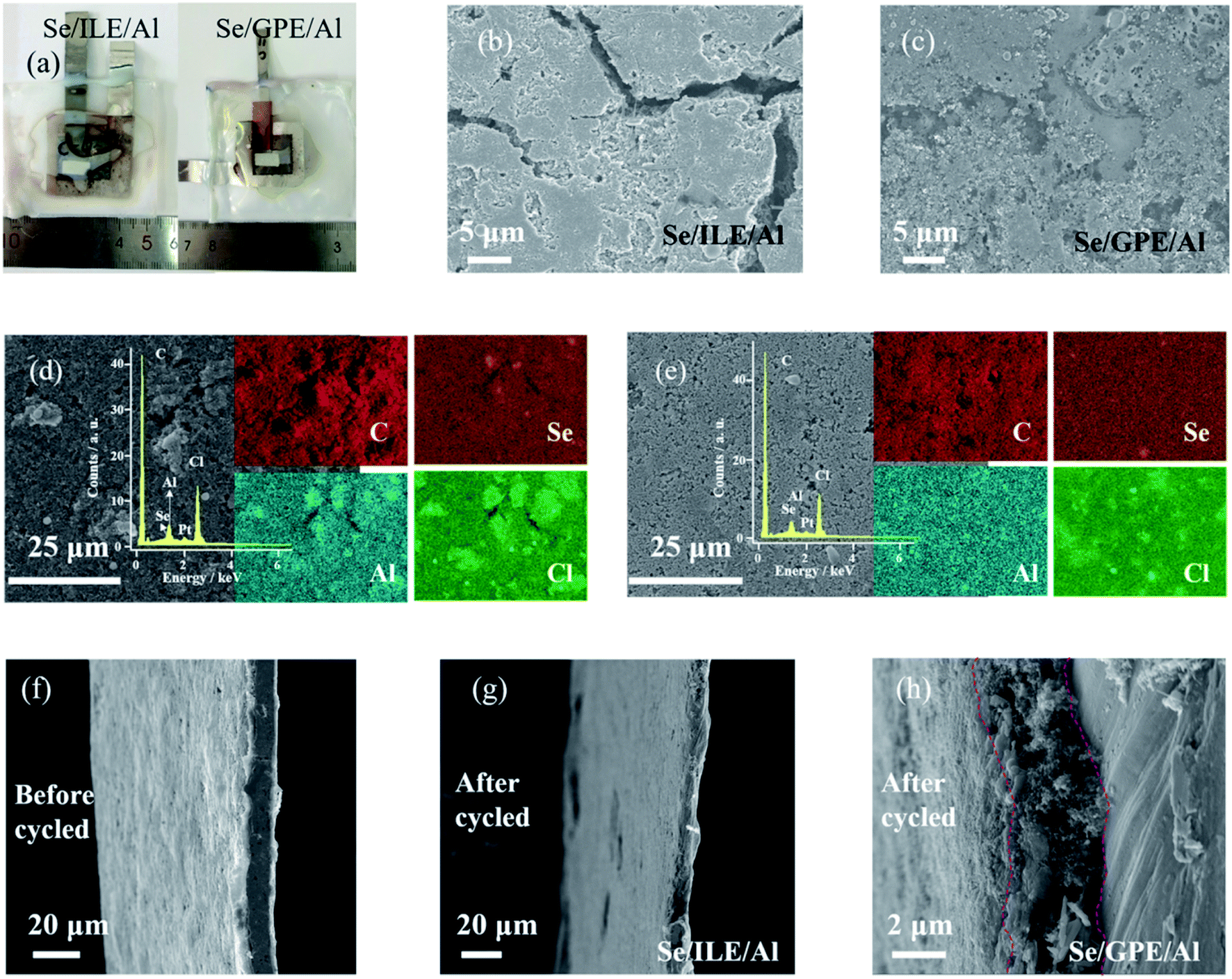 | ||
| Fig. 6 (a) Optical images of cycled Al–Se batteries with ILE and GPE. (b and c) FESEM image of cycled positive electrode of Al–Se batteries with ILE and GPE. (d) FESEM and corresponding EDS mapping images of Al, Cl, C, and Se of cycled positive electrode in ILE. (e) FESEM and corresponding EDS mapping images of Al, Cl, C, and Se of cycled positive electrode in GPE. (f–h) The cross-sectional FESEM image of positive electrode before cycling, 50th cycled in ILE, and 50th cycled in GPE. | ||
Fig. 6(f–h) shows the cross-sectional FESEM image of positive electrode before cycling, 50th cycled in ILE, and 50th cycled in GPE. It is obvious that the cross-section widths of selenium positive electrodes become narrower after reaction, which further confirming the dissolving effect. Meanwhile, the cross-section width of selenium positive electrode in GPE becomes smaller than ILE which probably due to the stickiness of GPE during sample preparation. As can be demonstrated from the Fig. 7, the poor fluidity, the stable and safe electrode–electrolyte interface of GPE can relieve the dissolution of the electrode materials and intermediate product to a certain extent than ILE, further greatly improving the electrochemical behaviors of the battery in the first few cycles. However, after hundreds of cycles, it still can't stop the dissolution. Further research is needed on ways to mitigate the dissolution.
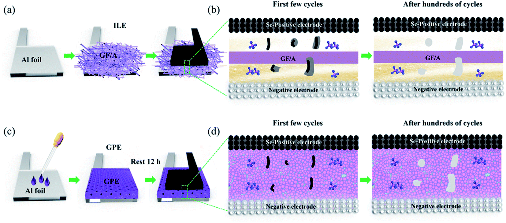 | ||
| Fig. 7 (a) Assembly diagram of the preparation of ILE. (b) Schematic diagram of intermediate product diffusion into the ILE. (c) Assembly diagram of the preparation of the GPE. (d) Schematic diagram of intermediate product diffusion into the GPE. | ||
4. Conclusions
In summary, a quasi-solid-state AIB has been established using the GPE between Se positive electrode and Al negative electrode, aiming to well addressing the critical capacity attenuation problems in the Al–Se battery with liquid electrolytes. Interestingly, compared with ILE, the incorporation of GPE in Al–Se battery shows lower self-discharge and obvious discharging platforms, and also greatly enhances the rate capacity and cycle stability. The GPE successfully prevent the loss of Se2Cl2 into the ILE, increases the utilization of the active materials, and promotes electronic conductivity and fast reaction kinetics in the first few cycles. Such performance improvement is probably attributed to the strong immobilization of soluble intermediate products by GPE.Conflicts of interest
The authors declare no competing financial interests.Acknowledgements
This work was supported by National Natural Science Foundation of China (51874019), Fundamental Research Funds for the Central Universities (FRF-TP-20-045A1), and China Postdoctoral Science Foundation (2020M680347 and 2021T140051).References
- N. Jayaprakash, S. K. Das and L. A. Archer, Chem. Commun., 2011, 47, 12610–12612 RSC.
- H. Sun, W. Wang, Z. Yu, Y. Yuan, S. Wang and S. Jiao, Chem. Commun., 2015, 51, 11892–11895 RSC.
- M. C. Lin, M. Gong, B. G. Lu, Y. P. Wu, D. Y. Wang, M. Y. Guan, M. Angell, C. X. Chen, J. Yang, B. J. Hwang and H. J. Dai, Nature, 2015, 520, 325–328 CrossRef PubMed.
- J. Tu, W. L. Song, H. Lei, Z. Yu, L.-L. Chen, M. Wang and S. Jiao, Chem. Rev., 2021, 121, 4903–4961 CrossRef CAS PubMed.
- Y. Zhang, S. Liu, Y. Ji, J. Ma and H. Yu, Adv. Mater., 2018, 1706310 CrossRef PubMed.
- M. Jiang, C. Fu, P. Meng, J. Ren, J. Wang, J. Bu, A. Dong, J. Zhang, W. Xiao and B. Sun, Adv. Mater., 2021, 2102026 CrossRef PubMed.
- C. P. Yang, S. Xin, Y. X. Yin, H. Ye, J. Zhang and Y. G. Guo, Angew. Chem., Int. Ed., 2013, 52, 8363–8367 CrossRef CAS PubMed.
- X. Huang, Y. Liu, C. Liu, J. Zhang, O. Noonan and C. Yu, Chem. Sci., 2018, 9, 5178–5182 RSC.
- Y. Kong, A. K. Nanjundan, Y. Liu, H. Song, X. Huang and C. Yu, Small, 2019, 15, 1904310 CrossRef CAS PubMed.
- S. C. Wu, Y. Ai, Y. Z. Chen, K. Wang, T. Y. Yang, H. J. Liao, T. Y. Su, S. Y. Tang, C. W. Chen, D. C. Wu, Y. C. Wang, A. Manikandan, Y. C. Shih, L. Lee and Y. L. Chueh, ACS Appl. Mater. Interfaces, 2020, 12, 27064–27073 CrossRef CAS PubMed.
- H. Lei, S. Jiao, J. Tu, W. L. Song, X. Zhang, M. Wang, S. Li, H. Chen and D. Fang, Chem. Eng. J., 2020, 385, 123452 CrossRef CAS.
- S. Liu, X. Zhang, S. He, Y. Tang, J. Wang, B. Wang, S. Zhao, H. Su, Y. Ren, L. Zhang, J. Huang, H. Yu and K. Amine, Nano Energy, 2019, 66, 104159 CrossRef CAS.
- Z. Li, J. Liu, X. Huo, J. Li and F. Kang, ACS Appl. Mater. Interfaces, 2019, 11, 45709–45716 CrossRef CAS PubMed.
- M. Liu, D. Zhou, Y.-B. He, Y. Fu, X. Qin, C. Miao, H. Du, B. Li, Q.-H. Yang, Z. Lin, T. S. Zhao and F. Kang, Nano Energy, 2016, 22, 278–289 CrossRef CAS.
- Z. Gao, H. Sun, L. Fu, F. Ye, Y. Zhang, W. Luo and Y. Huang, Adv. Mater., 2018, 30, 1705702 CrossRef PubMed.
- Z. Yu, S. L. Shang, D. Wang, Y. C. Li, H. P. Yennawar, G. Li, H.-T. Huang, Y. Gao, T. E. Mallouk, Z. K. Liu and D. Wang, Energy Storage Mater., 2019, 17, 70–77 CrossRef.
- Q. Zhao, S. Stalin, C. Z. Zhao and L. A. Archer, Nat. Rev. Mater., 2020, 5, 229–252 CrossRef CAS.
- C. Zhao, L. Liu, X. Qi, Y. Lu, F. Wu, J. Zhao, Y. Yu, Y.-S. Hu and L. Chen, Adv. Energy Mater., 2018, 8, 1703012 CrossRef.
- X. G. Sun, Y. Fang, X. Jiang, K. Yoshii, T. Tsuda and S. Dai, Polymer gel electrolytes for application in aluminum deposition and rechargeable aluminum ion batteries, Chem. Commun., 2016, 52, 292–295 RSC.
- Z. Yu, S. Jiao, S. Li, X. Chen, W. L. Song, T. Teng, J. Tu, H.-S. Chen, G. Zhang and D. N. Fang, Adv. Funct. Mater., 2018, 29, 1806799 CrossRef.
- Z. Yu, S. Jiao, J. Tu, W.-L. Song, H. Lei, H. Jiao, H. Chen and D. Fang, J. Mater. Chem. A, 2019, 7, 20348–20356 RSC.
- Q. Li and W. W. Yam, Chem. Commun., 2006, 9, 1006–1008 RSC.
- J. Zhang, Y. Xu, L. Fan, Y. Zhu, J. Liang and Y. Qian, Nano Energy, 2015, 13, 592–600 CrossRef CAS.
- L. Cheng, M. Shao, D. Chen, X. Wei, F. Wang and J. Hua, J. Mater. Sci.: Mater. Electron., 2008, 19, 1209–1213 CrossRef CAS.
- L. Liu, Y. Hou, X. Wu, S. Xiao, Z. Chang, Y. Yang and Y. Wu, Chem. Commun., 2013, 49, 11515–11517 RSC.
- B. Gates, B. Mayers, A. Grossman and Y. Xia, Adv. Mater., 2002, 14, 1749–1752 CrossRef CAS.
- M. Jia, C. Mao, Y. Niu, J. Hou, S. Liu, S. Bao, J. Jiang, M. Xu and Z. Lu, RSC Adv., 2015, 5, 96146–96150 RSC.
- L. B. Luo, J. S. Jie, Z. H. Chen, X. J. Zhang, X. Fan, G. D. Yuan, Z. B. He, W. F. Zhang, W. J. Zhang and S. T. Lee, J. Nanosci. Nanotechnol., 2009, 9, 6292–6298 CrossRef CAS PubMed.
- Q. Xie, J. Liu, J. Liang, W. Yu and Y. Qian, J. Nanosci. Nanotechnol., 2006, 6, 857–862 CrossRef CAS PubMed.
- T. Gao, X. Li, X. Wang, J. Hu, F. Han, X. Fan, L. Suo, A. J. Pearse, S. B. Lee, G. W. Rubloff, K. J. Gaskell, M. Noked and C. Wang, Angew. Chem., Int. Ed., 2016, 55, 9898–9901 CrossRef CAS PubMed.
- W. Chu, X. Zhang, J. Wang, S. Zhao, S. Liu and H. Yu, Energy Storage Mater., 2019, 22, 418–423 CrossRef.
- Y. Guo, Z. Hu, J. Wang, Z. Peng, J. Zhu, H. Ji and L. J. Wan, Angew. Chem., Int. Ed., 2020, 56, 22963–22967 CrossRef PubMed.
- X. Zhang, G. Zhang, S. Wang, S. Li and S. Jiao, J. Mater. Chem. A, 2018, 6, 3084–3090 RSC.
- S. Wang, S. Jiao, J. Wang, H. S. Chen, D. Tian, H. Lei and D. N. Fang, ACS Nano, 2016, 11, 469–477 CrossRef PubMed.
- H. Jiao, D. Tian, S. Li and C. Fu, ACS Appl. Energy Mater., 2018, 1, 4924–4930 CrossRef CAS.
- X. Zhang, S. Jiao, J. Tu, W. L. Song, X. Xiao, S. Li, M. Wang, H. Lei, D. Tian, H. Chen and D. Fang, Energy Environ. Sci., 2019, 12, 1918–1927 RSC.
- P. Nova and O. Inganos, J. Electrochem. Soc., 1988, 135, 2485–2490 CrossRef.
- G. Li, M. Kou, J. Tu, Y. Luo, M. Wang and S. Jiao, Chem. Eng. J., 2021, 421, 127792 CrossRef CAS.
- X. Wang, H. Hao, J. Liu, T. Huang and A. Yu, Electrochim. Acta, 2011, 56, 4065–4069 CrossRef CAS.
| This journal is © The Royal Society of Chemistry 2021 |