 Open Access Article
A sensitive platform for DNA detection based on organic electrochemical transistor and nucleic acid self-assembly signal amplification
Chaohui Chen *,
Qingyuan Song,
Wangting Lu,
Zhengtao Zhang,
Yanhua Yu,
Xiaoyun Liu and
Rongxiang He*
Key Laboratory of Optoelectronic Chemical Materials and Devices of Ministry of Education, College of Photoelectric Materials and Technology, Jianghan University, Wuhan 430056, PR China. E-mail: chaohui20071220@163.com; herx@jhun.edu.cn
First published on 24th November 2021
Abstract
Highly sensitive detection of DNA is of great importance for the detection of genetic damage and errors for the diagnosis of many diseases. Traditional highly sensitive organic electrochemical transistor (OECT)-based methods mainly rely on good conductivity materials, which may be limited by complex synthesis and modification steps. In this work, DNA biosensor based on OECT and hybridization chain reaction (HCR) signal amplification was demonstrated for the first time. Au nanoparticles were electrochemically deposited on the Au gate electrode to increase the surface area. Then, the HCR products, long negatively charged double-stranded DNA, were connected to the target by hybridization, which can increase the effective gate voltage offset of OECT. This sensor exhibited high sensitivity and even 0.1 pM target DNA could be directly detected with a significant voltage shift. In addition, it could discriminate target DNA from the mismatched DNA with good selectivity. This proposed method based on HCR in DNA detection exhibited an efficient amplification performance on OECT, which provided new opportunities for highly sensitive and selective detection of DNA.
1. Introduction
Highly sensitive and accurate DNA detection methods are essential for medical diagnosis, food analysis and environmental monitoring.1–3 Traditional laboratory methods, such as fluorescent labels,4 scanning Kelvin probe microscopy (SKPM),5 colorimetric assays,6 exhibit great sensitivity and accuracy. However, these methods are expensive and complicated, as they require either fluorescent label for signal detection, or complex procedures for sample preparation. Therefore, there is an urgent need to develop novel nucleic acid detection technologies that are highly sensitive, inexpensive and convenient, as these characteristics will promote rapid and efficient diagnosis of diseases in resource-limited environments.Organic electrochemical transistors (OECTs) is ideally-suited for DNA detection due to its inherent amplification capability, low cost and easy fabrication.7,8 A typical OECT device consists of drain, source and gate electrodes. The channel between the drain and the source is connected by an active layer of organic semiconductor such as poly(3,4-ethylenedioxythiophene):polystyrene sulfonate (PEDOT:PSS). Due to the electrochemical doping/dedoping effects of the active layer by the electrolyte, the channel current of the OECT can be modulated by the gate voltage.9 Therefore, by monitoring the changes in channel current, any charge transfer reaction that changes the surface potential of the gate electrode can be measured.10–13 Moreover, OECTs can work stably in aqueous environments with a low operating voltage (<1 V), which is essential for DNA analysis. Thus, various OECT-based DNA sensors have been developed.14–16 However, the concentration of target DNA is often very low. In order to further improve the sensitivity, most reported methods either use bulk platinum as gate electrode or need to introduce excellent conductive nanomaterials such as carbon nanotubes,17 graphene18 and polyelectrolyte multilayers.19 The synthesis and modification steps of conductive nanomaterials are cumbersome and complicated, which limited their applications.
DNA amplification can provide an alternative way to resolve the above issue.20–22 So far, a variety of signal amplification strategies have been established, such as rolling circle amplification (RCA),23 loop-mediated amplification24 and hybridization chain reaction (HCR).25,26 Among these methods, HCR-based nucleic acid self-assembly signal amplification, a type of toehold mediated strand displacement reaction, has attracted enormous attention due to its simple operation and excellent amplification efficiency.27–29 In a typical HCR, an initiator can trigger a cascade of hybridization events between two auxiliary probes of H1 and H2, and produce a nicked double-stranded DNA (dsDNA) with tens to hundreds of repeated units, which is similar to alternate copolymers.30 Therefore, with the introduction of HCR-based nucleic acid self-assembly into OECT, a small amount of the target can produce long dsDNA, making more negative charges accumulate on the gate electrode and cause a significant change in the gate potential.
Herein, we reported a novel biosensor for DNA detection based on HCR signal amplification and OECT device for the first time. The human papillomavirus 18 L1 gene oligonucleotide sequence was selected as the target DNA. In the presence of the target, the attached negatively charged HCR products in OECT could increase the effective gate voltage offset. Thus, by monitoring the potential of gate electrode, the concentration of target DNA can be determined. This sensing platform only needs to incubate the nucleic acids to achieve signal amplification, which is very simple and convenient.
2. Experimental
2.1 Materials
Dimethylsulfoxide (99.9%, DMSO), 3-mercaptopropyl trimethoxysilane (95%, MPTMS), tris(2-carboxyethyl)phosphine (≥98%, TCEP), hydrogen tetrachloroaurate(III) trihydrate (≥99.9%, HAuCl4·3H2O) and tris(hydroxymethyl)aminomethane hydrochloride (≥99.8%, Tris) were purchased from Sigma-Aldrich (St. Louis, MO, USA). Poly(3,4-ethylenedioxythiophene)–poly(styrene sulfonate) (1.2% PEDOT:PSS, Clevios, PH1000) was purchased from Heraeus (Germany). Acetone (≥97.0%), isopropanol (≥99.8%, IPA) and absolute ethanol (95%) were purchased from Sinopharm Chemical Reagent Co. Ltd (Shanghai, China). All DNA oligonucleotides with different sequences were synthesized and high-performance liquid chromatography purified by Sangon Biotechnology Co. Ltd. (Shanghai, China) and were stored in 10 mM Tris–HCl buffer (1 mM EDTA, pH 8.00). The sequences of the oligonucleotides are listed in Table 1.| Primer | Sequence (5′–3′) |
|---|---|
| SH-DNA | SH-CCACGTCTAATGTTTCTGAGGA |
| Target DNA | CTACAGACACATTGTCCCTAACGTCCTCAGAAACATTAGACGTGG |
| Linker DNA | TTAGGGACAATGTGTCTGTAGACTAAAAGGGTCTGAGGG |
| H1 | TACTCCCCCAGGTGCCCCTCAGACCCTTTTAGT |
| H2 | GCACCTGGGGGAGTAACTAAAAGGGTCTGAGGG |
| Mismatched DNA | AGATCCTCTCTCTGAAATCACTGAGCAGGAGAAAGATTTTCTATGGAGTCACAGA |
All other chemicals not mentioned here were of analytical-reagent grade or better. Ultrapure water was produced by a Millipore-Q Academic Water Purification System (Bedford, MA, USA).
2.2 OECT device fabrication
PEDOT:PSS based OECT were fabricated on glass substrates according to our previous work.31 Firstly, Cr/Au (10 nm/100 nm) film was deposited on the glass substrates through magnetic sputtering and then patterned through soft lithography. The length and width of the channel between drain and source electrodes were 0.2 mm and 8 mm, respectively. The width and length of the gate electrode were 2 mm. In order to increase the interaction area, Au nanoparticles (Au NPs) were electrochemistry deposited on the gate electrode in a 1 mg mL−1 chloroauric acid electroplating solution under a 0.1 V constant voltage for 2 hours at room temperature. After the substrates with electrode were washed with ethanol, acetone and DI water in sequence, PEDOT:PSS with 5 v/v% (MPTMS) and 5 v/v% DMSO was spin-coated on the source and drain electrodes to form an organic channel. Then, the device was annealed on a hot plate (IKA HS7, Germany) at 150 °C for 1 hour in a glove box (IT, USA) filled with high purity N2.2.3 DNA immobilization, hybridization chain reaction and detection
Thiolated oligonucleotides (10 μL, 20 μM) were incubated with TCEP·HCl (10 μL, 20 mM) for 1 h to reduce the disulfide bond. Then, 10 μL of the reduced SH-DNA was dropped on the surface of Au gate electrode and allowed to react overnight at room temperature. The Au gate electrode was washed three times with PBS (10 mM Na2HPO4, 10 mM NaH2PO4, 150 mM NaCl, pH 7.40) to remove the unbound SH-DNA from the surface. Different concentrations of the target DNA were dropped on SH-DNA decorated Au gate and incubated for 1 h. After rinsing Au gate three times with PBS buffer, the linker DNA (10 μL, 10 μM) hybridized with the target DNA for 1 h. Subsequently, the HCR (10 μL, 1 μM) products were dropped on Au gate and hybridized with linker DNA for 1 h.The HCR was performed by mixing H1 (10 μL, 2 μM) and H2 (10 μL, 2 μM) in the Tris–HCl buffer (10 mM Tris, 500 mM NaCl, pH 8.00), followed by incubating at 37 °C for 2 h with gentle shaking.
2.4 Gel electrophoresis and SEM characterization
The HCR products (9 μL, 1 μM) were mixed with SYBR Green I (1 μL, 100×) for 10 min. The products were then loaded onto a 3% agarose gel and electrophoresed in 1× Tris–acetate–EDTA (TAE) buffer (40 mM TrisAcOH, 2.0 mM Na2EDTA, pH 8.50) at 100 V for 40 min. The gel was scanned using the syngene G:BOX Chemi XRQ (Cambridge, UK).For SEM characterization, the HCR products (1 μL, 1 μM) were dropped on Au gate and hybridized with linker DNA for 1 h. Then, the samples were washed with DI water and dried overnight. After gold sputtering of the samples, the morphology and length of assembled HCR products were obtained directly from FE-SEM (SU8010, Hitachi, Japan).
2.5 OECT detection
The OECT devices were characterized using a semiconductor parameter analyzer (Keithley, 4200-SCS, USA). The devices were immersed in PBS solutions during the detection. The channel current IDS between the drain and source electrodes was measured as a function of Au gate voltage VG while the channel voltage was constant (VDS = 0.05 V).3. Results and discussion
3.1 The detection principle of devices
In this work, PEDOT:PSS based organic electrochemical transistors were used to detection DNA. As shown in Fig. 1, cations in the PBS solution, such as Na+, can be injected into the PEDOT:PSS film, which is regarded as an electrochemical dedoping process of the film. The injected cations in the film can reduce PEDOT, which is from the oxidized state to the neutral state.32 In this way, the conductive of PEDOT:PSS film was modulated by the injective cations. The concentration of injected cations from the electrolyte was controlled by the gate voltages and the electric double layer. When the voltage between gate electrode and source electrode is positive, the cations in the electrolyte were injected into the PEDOT:PSS film and induced a decrease channel current. The transfer characterization of PEDOT:PSS based OECT was shown in Fig. 1, where Au was used as the gate electrode. Au nanoparticles were electrodeposited on the Au gate electrodes to increase the surface area, which can increase the modification efficiency of SH-DNA probe. The SH-DNA can hybridize with 3′ end of target DNA, which is utilized to detect DNA. The hybridization of DNA, which is from single stranded DNA (ssDNA) to dsDNA, can induce a voltage drop on the gate voltage. This voltage drop can be detected by the transfer characterization of OECT.18,33,34 This means that the state change of DNA can induce a voltage drop. Therefore, there will induce another voltage drop when the length of the target DNA increased.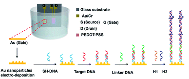 | ||
| Fig. 1 Schematic illustration of the PEDOT:PSS based OECT and the gate modification for DNA detection. | ||
In order to increase the length of the target DNA, HCR was utilized, as shown in Fig. 1. A 3′ end of linker DNA is need to hybridize with the 5′ end of the target DNA and the 5′ end of linker DNA is complementary to the 3′ end of H1. Then, the 5′ exposed end of H1 can be hybridized with the 3′ end of H2, making the 5′ end of H2 exposed. The newly exposed 5′ end of H2 can hybridize with another H1 and start a new cycle. In this way, a single target can generate long-range H1–H2 complexes, which enlarged the length of target DNA and increased the voltage drop on the Au gate electrodes. On one hand, in the absence of the target DNA, the linker DNA can be washed away. On the other hand, without the linker DNA, the HCR products can't be conjugated to the Au gate electrode and there is no voltage drop on the gate. In this way, the sensitivity of DNA detection can be increased through hybridization chain reaction.
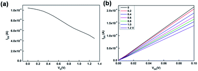
Fig. 2a shows the transfer characteristics of the OECT with Au gate electrode measured in PBS solution (VDS = 0.05 V). The replication transfer tests indicated that OECT device had good stability. The output characteristics was shown in Fig. 2b. From the transfer characteristic, it indicated that the channel current decreased when the gate voltage increased. Therefore, during the DNA detection, compared to the control transfer line, if the test transfer line was shift to high gate voltage, it means that there is a negative offset voltage applied on the gate electrode.
3.2 Feasibility of the HCR-based OECT sensor
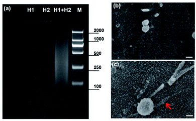
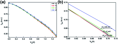
To demonstrate the practicable of the hybridization chain reaction, the hybridization results were confirmed by agarose gel electrophoresis. As shown in Fig. 3a, there was no band of 1 μM H1 or 1 μM H2 and a new smear band appeared when 1 μM H1 was mixed with and 1 μM H2, indicating that the HCR had taken place and long-nicked dsDNA was formed. The results of agarose gel electrophoresis were consistent with previous report.35 After the hybridization chain reaction of DNA on Au electrode, the substrate was characterized by SEM. Fig. 3b showed the SEM characterization of the electrochemical deposited Au nanoparticles on Au electrode. Compared to the unmodified Au nanoparticles, long-range double helices on Au nanoparticles could be found, as indicated by the red arrow in Fig. 3c.In order to demonstrate the viability of HCR induced OECT signal amplification in DNA detection, the transfer characterization was test under different conditions according to the strategy in Fig. 1. After the modification of SH-DNA on Au gate electrode, target DNA with a concentration of 1 pM was added. As shown in Fig. 4, compared to the transfer characterization of SH-DNA (curve a), there is no obvious gate voltage offset in target DNA (curve b). When the linker DNA was added, the transfer curve (curve c) shifts to higher positive gate voltage, which is about 7 mV. When the HCR (H1 and H2) products were added to enlarge the DNA strands, the transfer curve (curve d) shifts to much higher positive gate voltage. As shown in Fig. 4, the effective gate voltage offset is about 35 mV. These results indicated that HCR can be used as a signal amplifier in the OECT biosensor to increase the sensitivity.
3.3 Selectivity of the HCR-based OECT sensor
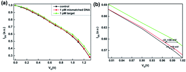
The specificity of the PEDOT:PSS based OECT for DNA detection was examined by measuring the transfer characterizations (IDS–VG, VDS = 0.05 V) using target DNA and mismatched DNA under the same condition. As shown in Fig. 5a, in the presence of target DNA, it could hybridize with SH-DNA and conjugate to the Au gate electrode. Subsequently, linker DNA initiated HCR amplification and generated long-range H1–H2 complexes, which enlarged the length of target DNA and increased the voltage drop. In the presence of mismatched DNA, the mismatched DNA couldn't hybridize with SH-DNA, so that the mismatched DNA and linker DNA were washed away. Without the linker DNA, the HCR products couldn't conjugate to the Au gate electrode. Therefore, there was no voltage drop on the gate. These results indicated that the SH-DNA probe has a good specific selectivity towards the target DNA and that the effect of nonspecific adsorption of the mismatched DNA on the OECT is very weak. As shown in Fig. 5b, the relative shift of the gate voltage after the target DNA were captured by the SH-DNA was about 45 mV.3.4 Sensitivity of HCR-based OECT sensor
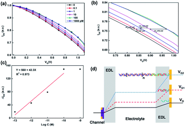
Based on the selectivity and HCR signal amplification, the sensitivity of OECT biosensors was investigated. Therefore, different concentrations of target DNA were detected by the HCR based OECT biosensor. After the SH-DNA was modified on the Au gate electrodes, the transfer characteristic was test in PBS solution as a baseline. Then, different concentration of target DNA was added. After the target DNA reacted with linker DNA and HCR products, the transfer characteristics were test in PBS solution. As shown in Fig. 6a, the transfer curve shifted to higher positive gate voltage when the concentration of target DNA increased. This meant that there was an effective negative gate voltage applied on the gate electrodes. As shown in Fig. 6b, when the concentration of target DNA was 0.1 pM, the effective shift gate voltage was about 19 mV. When the concentration of target DNA increased to 1 nM, the effective shift gate voltage increased to about 150 mV. A good linear relationship was obtained between the effective gate voltage offsets and the target DNA concentration in a range of 1 × 10⁻¹³ to 1 × 10⁻¹⁰ M (Fig. 6c). The limit of detection was calculated to be 5.75 × 10⁻¹⁴ M (3σ/k). Besides, the slope is about 42 mV per decade. In graphene-based transistor for label-free DNA detection, the effective gate voltage shift is about 30 mV in the presence of 1 pM target,18 which is smaller than that of using the HCR based OECT device. In Lin's method,34 10 pM target can be detected by using electric pulse to enhance the hybridization of DNA. In our work, the detectable concentration was about 0.1 pM, which is more sensitive than that of the electric pulse method (10 pM). Therefore, the HCR based signal amplification can improve the sensitivity of DNA detection in OECT biosensor.For the principle of OECT based biosensor, the shift of transfer characteristic was mainly due to the potential drops between the double electrical layers on the gate electrode and organic film. As shown in the Fig. 6d, there are two double electrical layer (EDL). The gate voltage can be applied on the PEDOT:PSS film through the EDLs. When the SH-DNA was hybridized by the target DNA, there was a potential drop occurs in the EDL on Au gate electrode. When the target DNA was modified by linker DNA and reacted by HCR, there was a larger potential drop on the Au gate electrode. This is because the ssDNA is negatively charged. When ssDNA hybridizes to form dsDNA, the charges of DNA are increased, resulting in an increase in the electronegativity of the gate electrode, which is equivalent to applying a negative voltage on the gate electrode, causing the transfer curve to shift positively. This potential change after the hybridization or HCR can be expressed as follow:5
 | (1) |
4. Conclusions
In conclusion, a simple, selective, and sensitive DNA biosensor was developed, which integrated HCR signal amplification with OECT device. With the introduction of HCR on the Au gate electrode, the signal in the presence of the target is amplified, which in turn increases the effective voltage drop on the double electric layer of the gate electrode, resulting a large shift in OECT transmission characteristics. A good linear relationship was obtained in the range from 0.1 pM to 1 nM, with a slope of approximately 42 mV per decade. Besides, this method can distinguish 1 pM target DNA from mismatched DNA, which exhibits good selectivity. This approach could provide a new insight for improving the sensitivity of OECT-based method, showing great potential in biochemical applications.Author contributions
Chaohui Chen: methodology, validation, data curation, writing – original draft, funding acquisition. Qingyuan Song: device fabrication, data curation. Wangting Lu: SEM characterization. Zhengtao Zhang: software. Yanhua Yu and Xiaoyun Liu provided advice and assisted in reviewing the original draft. Rongxiang He: methodology, validation, data curation, writing – review & editing, funding acquisition.Conflicts of interest
There are no conflicts to declare.Acknowledgements
This work was financially supported by the Natural Science Foundation of Hubei Province (2020CFB193), Wuhan Municipal Science and Technology Bureau (Applied Foundation Frontier Project, 2019020701011440) and the Foundation of Jianghan University (2021KJZX001). We also acknowledge the financial support from the Youth Talent Support Program and the Foundation of Cultivation of Scientific Institutions of Jianghan University.References
- S. Chen, Y. Sun, Y. Xia, K. Lv, B. Man and C. Yang, Biosens. Bioelectron., 2020, 156, 112128 CrossRef CAS PubMed
.
- J. E. van Dongen, J. T. W. Berendsen, R. D. M. Steenbergen, R. M. F. Wolthuis, J. C. T. Eijkel and L. I. Segerink, Biosens. Bioelectron., 2020, 166, 112445 CrossRef CAS PubMed
.
- B. S. Batule, Y. Seok and M. G. Kim, Biosens. Bioelectron., 2020, 151, 111998 CrossRef CAS PubMed
.
- J. Chen, M. Wang, X. Zhou, Y. Nie and X. Su, Sens. Actuators, B, 2021, 326, 128847 CrossRef CAS
.
- M. Thompson, L. E. Cheran, M. Zhang, M. Chacko, H. Huo and S. Sadeghi, Biosens. Bioelectron., 2005, 20, 1471–1481 CrossRef CAS PubMed
.
- C. Chen and X. Ji, Chin. Chem. Lett., 2018, 29, 1287–1290 CrossRef CAS
.
- J. Hu, W. Wei, S. Ke, X. Zeng and P. Lin, Electrochim. Acta, 2019, 307, 100–106 CrossRef CAS
.
- P. R. Paudel, J. Tropp, V. Kaphle, J. D. Azoulay and B. Lüssem, J. Mater. Chem. C, 2021, 9, 9761–9790 RSC
.
- G. Mehes, A. Roy, X. Strakosas, M. Berggren, E. Stavrinidou and D. T. Simon, Adv. Sci., 2020, 7, 2000641 CrossRef CAS PubMed
.
- K. Lieberth, P. Romele, F. Torricelli, D. A. Koutsouras, M. Bruckner, V. Mailander, P. Gkoupidenis and P. W. M. Blom, Adv. Healthcare Mater., 2021, 10, e2100845 CrossRef PubMed
.
- H. Liu, A. Yang, J. Song, N. Wang, P. Lam, Y. Li, K. W. Law Helen and F. Yan, Sci. Adv., 2021, 7, eabg8387 CrossRef CAS PubMed
.
- R. B. Rashid, X. Ji and J. Rivnay, Biosens. Bioelectron., 2021, 190, 113461 CrossRef CAS PubMed
.
- P. Romele, P. Gkoupidenis, D. A. Koutsouras, K. Lieberth, Z. M. Kovács-Vajna, P. W. M. Blom and F. Torricelli, Nat. Commun., 2020, 11, 3743 CrossRef CAS PubMed
.
- R. Bruch, G. A. Urban and C. Dincer, Nat. Biomed. Eng., 2019, 3, 419–420 CrossRef PubMed
.
- R. Hajian, S. Balderston, T. Tran, T. deBoer, J. Etienne, M. Sandhu, N. A. Wauford, J. Y. Chung, J. Nokes, M. Athaiya, J. Paredes, R. Peytavi, B. Goldsmith, N. Murthy, I. M. Conboy and K. Aran, Nat. Biomed. Eng., 2019, 3, 427–437 CrossRef CAS PubMed
.
- Y. Fang, X. Li and Y. Fang, J. Mater. Chem. C, 2015, 3, 6424–6430 RSC
.
- L. Kergoat, B. Piro, D. T. Simon, M. C. Pham, V. Noel and M. Berggren, Adv. Mater., 2014, 26, 5658–5664 CrossRef CAS PubMed
.
- S. Li, K. Huang, Q. Fan, S. Yang, T. Shen, T. Mei, J. Wang, X. Wang, G. Chang and J. Li, Biosens. Bioelectron., 2019, 136, 91–96 CrossRef CAS PubMed
.
- A. M. Pappa, S. Inal, K. Roy, Y. Zhang, C. Pitsalidis, A. Hama, J. Pas, G. G. Malliaras and R. M. Owens, ACS Appl. Mater. Interfaces, 2017, 9, 10427–10434 CrossRef CAS PubMed
.
- D. Ye, J. Wang, H. Shen, X. Feng, L. Xiang, W. Jin, W. Zhao, J. Ding, Z. He, Y. Zou, Q. Meng, W. Cui, F. Zhang, C. A. Di, C. Fan and D. Zhu, Adv. Mater., 2021, 2100489 CrossRef CAS PubMed
.
- H. Wang, C. Li, X. Liu, X. Zhou and F. Wang, Chem. Sci., 2018, 9, 5842–5849 RSC
.
- Y. X. Chen, K. J. Huang and K. X. Niu, Biosens. Bioelectron., 2018, 99, 612–624 CrossRef CAS PubMed
.
- J. Jiao, C. Duan, J. Zheng, D. Li, C. Li, Z. Wang, T. Gao and Y. Xiang, Biosens. Bioelectron., 2021, 178, 113032 CrossRef CAS PubMed
.
- X. Zhu, X. Wang, L. Han, T. Chen, L. Wang, H. Li, S. Li, L. He, X. Fu, S. Chen, M. Xing, H. Chen and Y. Wang, Biosens. Bioelectron., 2020, 166, 112437 CrossRef CAS PubMed
.
- C. Chen, Y. Liu, Z. Zheng, G. Zhou, X. Ji, H. Wang and Z. He, Anal. Chim. Acta, 2015, 880, 1–7 CrossRef CAS PubMed
.
- H. Chai, W. Cheng, D. Jin and P. Miao, ACS Appl. Mater. Interfaces, 2021, 13, 38931–38946 CrossRef CAS PubMed
.
- C. Zhang, J. Chen, R. Sun, Z. Huang, Z. Luo, C. Zhou, M. Wu, Y. Duan and Y. Li, ACS Sens., 2020, 5, 2977–3000 CrossRef CAS PubMed
.
- H. Sun, F. Yao, Z. Su and X.-F. Kang, Biosens. Bioelectron., 2020, 150, 111906 CrossRef CAS PubMed
.
- S. Bi, S. Yue and S. Zhang, Chem. Soc. Rev., 2017, 46, 4281–4298 RSC
.
- C. A. Figg, P. H. Winegar, O. G. Hayes and C. A. Mirkin, J. Am. Chem. Soc., 2020, 142, 8596–8601 CrossRef CAS PubMed
.
- R. X. He, M. Zhang, F. Tan, P. H. M. Leung, X. Z. Zhao, H. L. W. Chan, M. Yang and F. Yan, J. Mater. Chem., 2012, 22, 22072 RSC
.
- P. Lin, F. Yan and H. L. W. Chan, ACS Appl. Mater. Interfaces, 2010, 2, 1637–1641 CrossRef CAS PubMed
.
- J. Song, P. Lin, Y. F. Ruan, W. W. Zhao, W. Wei, J. Hu, S. Ke, X. Zeng, J. J. Xu, H. Y. Chen, W. Ren and F. Yan, Adv. Healthcare Mater., 2018, 7, e1800536 CrossRef PubMed
.
- P. Lin, X. Luo, I. M. Hsing and F. Yan, Adv. Mater., 2011, 23, 4035–4040 CrossRef CAS PubMed
.
- N. Li, J. Chen, M. Luo, C. Chen, X. Ji and Z. He, Biosens. Bioelectron., 2017, 87, 325–331 CrossRef CAS PubMed
.
| This journal is © The Royal Society of Chemistry 2021 |

