 Open Access Article
Facile preparation of high loading filled PVDF/BaTiO3 piezoelectric composites for selective laser sintering 3D printing†
Shiping Song,
Yijun Li ,
Qi Wang and
Chuhong Zhang
 *
*
State Key Laboratory of Polymer Materials Engineering, Polymer Research Institute, Sichuan University, Chengdu, 610065, China. E-mail: chuhong.zhang@scu.edu.cn
First published on 24th November 2021
Abstract
3D printed piezoelectric devices, due to their sufficient multidimensional deformation and excellent piezoelectric properties, are one of the most promising research directions. However, the lack of high loaded piezoelectric composites is the key bottleneck restricting the enhancement of the piezoelectric output. In this work, we successfully prepared a novel high loaded polyvinylidene fluoride (PVDF)/barium titanate (BaTiO3) piezoelectric composite suitable for selective laser sintering (SLS) 3D printing via solid state shear milling (S3M) technology. The 50 wt% BaTiO3 filling made the most outstanding contribution to the piezoelectric properties of the composites. The 3D printed cymbal parts with a stress amplification effect exhibited outstanding piezoelectric conversion efficiency and responsiveness, whose open circuit voltage and short circuit current could reach 20 V and 1.1 μA, respectively. This work not only contributed a new high loaded piezoelectric composite for SLS processing, but also provided a novel piezoelectric performance enhancement strategy by the construction of 3D structure.
1. Introduction
With the rapid technological and economic development of our societies, an intelligent industry centered on new materials and new equipments is gradually rising all around the world.1,2 Due to the ability to realize the mutual conversion of mechanical energy and electrical energy,3–5 piezoelectric materials have aroused great interest in practical applications, and are widely used in sensing, energy storage, electronics and other fields.6,7 For example, Li et al.8 demonstrated a non-lead (ZnO) piezoelectric device powered by heart movement. Cheng et al.9 reported a self-powered PVDF sensor for blood pressure monitoring. However, restricted by conventional processing technology, piezoelectric materials are usually only manufactured into two-dimensional (2D) thin films or sheets,10 whose normal space cannot be fully utilized to produce sufficient deformation, resulting in a limited stress-to-electricity conversion efficiency.11 Compared with 2D parts, the modulus and deformation of three-dimensional (3D) parts can be adjusted by introducing arrays,12 holes,13 lattices14 and other structures, so as to effectively compensate for the lack of normal deformation in traditional piezoelectric devices and enhance the piezoelectric output.15 3D printed piezoelectric devices have received extensive attention due to their high-efficiency stress-to-electricity conversion and have been recognized as one of the most promising research fields.16The composition of materials has a crucial influence on the final performance of 3D printed parts.17 Nowadays, piezoelectric polymer materials, e.g. polyvinylidene fluoride (PVDF)18 and nylon 11 (PA11),19 have the advantages of good flexibility, low density and excellent processability.20 But such polymers cannot satisfy the needs of practical applications due to their low piezoelectric strain constant and conversion efficiency.21 Piezoelectric ceramics, featuring high piezoelectric constant, figure of merit, Curie temperature and stability, are currently the most applied piezoelectric materials,22 such as lead zirconate titanate (PZT), barium titanate (BaTiO3), etc.23,24 Therefore, piezoelectric composite materials marrying both the advantages of piezoelectric polymers and piezoelectric ceramics are highly desired for a more satisfactory performance in 3D printing technology.25
The filling amount of piezoelectric ceramics is the key factor that determines the piezoelectric properties of the materials. Qi et al.26 reported that 80 wt% BaTiO3 composited with PA11 could exhibit excellent piezoelectric properties. Chamankar et al.27 prepared a PVDF/PZT high loaded composite with improved piezoelectric properties. More and more researchers in the piezoelectric field are focusing on increasing the filling amount of piezoelectric ceramics. However, the common preparation methods of piezoelectric composites mainly employ approaches such as melt blending and solution methods.28 The obtained composite materials usually exhibit improved processing properties and piezoelectric performances, but because of the polarity difference between the polymer and ceramic,29 there still remain three main problems: (1) poor interface compatibility, (2) low content filling and (3) severe agglomeration of ceramics.30 In view of the above technical bottleneck, the filling amount of piezoelectric ceramics in the matrix is mostly less than 30 wt%, hindering the further improvement of the piezoelectric performances. The pursuit of a clean and efficient method for the preparation of high filling piezoelectric composites is practically imperative.
Solid state shear milling (S3M) is a facile technology for processing polymers and modifying organic/inorganic interfaces, based on the principle of polymer mechanochemistry and its unique three-dimensional scissoring structure learning from traditional Chinese stone mills.31 During S3M treatments, a large number of shear unit cells can be formed by two milling pans with relative motion and embedded grooves, and the shape and volume of these shear unit cells change periodically.32 With strong pressure, it seems that many 3D scissors continuously cut the materials, and this enables the grinding and dispersion of the materials at room temperature.33 Therefore, S3M equipment can effectively eliminate the agglomeration between ceramic particles and improve the interface compatibility,34 which has great advantages in the large-scale preparation of polymer-based piezoelectric composite powder with high content filling.
As an important 3D printing technology, selective laser sintering (SLS) can design and construct 3D complex structures by layer-by-layer processing of powder materials.35 The technical advantages of SLS mainly lie in the ability to manufacture parts with a unique geometric creativity and enhance design flexibility without any expensive additional tools,36 and it does not involve the rheology and interface compatibility issue of the composites. So SLS might be the most suitable 3D printing technology for processing high loaded piezoelectric composites. It is expected that the 3D piezoelectric parts prepared by SLS can take full advantage of the piezoelectric coefficients in multiple directions and thus boost the piezoelectric properties.37
PVDF is a typical piezoelectric polymer material, and exhibits excellent flexibility and processability.38 As a semi-crystalline and polymorphous polymer, PVDF comprises α, β, γ, δ and ε crystal phases with distinct chain conformations, among which the β crystal, consisting of repetitive TTTT conformation units, exhibits the best piezoelectric properties.39,40 Therefore, high β phase amount is the key to obtain excellent stress-to-electricity conversion efficiency. BaTiO3 is a widely applied lead-free piezoelectric ceramic material due to its high electromechanical coupling coefficient and piezoelectric constant. However, it is hard, brittle and intolerant to mechanical impact, which greatly limits its piezoelectric applications.41 People have made great efforts in addressing these issues; for instance, Yang et al.42 reported a flexible piezoelectric pressure sensor based on a polydopamine-modified BaTiO3/PVDF composite film for human motion monitoring. The 17 wt% PDA@BTO/PVDF sensor exhibited a remarkable piezoelectric output voltage of 9.3 V. Jiang et al.43 prepared a flexible piezoelectric pressure tactile sensor based on BaTiO3/PVDF composites by the electrospinning technique, which displayed excellent flexibility and a linear response to external mechanical force. Yang et al.24 introduced PVDF/BaTiO3/CNT piezoelectric energy harvesters with bionic balsa wood structures prepared by 3D printing and supercritical carbon dioxide foaming. The open circuit voltage and short circuit current could reach 19.3 V and 415 nA, respectively.
Herein, we for the first time report a new PVDF/BaTiO3 piezoelectric composite with a high content filling and uniform distribution by S3M technology and its piezoelectric application in SLS 3D printing. A series of one-piece cymbal parts with excellent piezoelectric properties and responsiveness were designed and manufactured. Three issues were addressed: (1) the dispersion morphology of the composites, (2) the crystallization behaviors of PVDF in SLS and (3) the enhancement mechanism of the piezoelectric properties generated by the cymbal parts. This work not only provides a new type of piezoelectric composite suitable for SLS, but also exhibits great guiding significance for the structural design of 3D piezoelectric parts during SLS processing.
2. Experimental
2.1 Materials
PVDF (FR906, Tm = 170 °C, ρ = 1.77 g cm−3) was provided by Shanghai 3F New Material Technology Co., Ltd., China. BaTiO3 (ρ = 6.08 g cm−3, average particle size = 500 nm) was supplied by Shandong Sinocera Functional Material Co., Ltd., China. The fumed silica (average particle size = 12 nm) was purchased from Evonik, Germany.2.2 Preparation of the PVDF/BaTiO3 composite powder and the selective laser sintering process
A schematic illustration of the preparation and SLS processing of the PVDF/BaTiO3 nanocomposites is shown in Fig. 1. Initially, PVDF pellets with 25 wt%, 50 wt% or 75 wt% BaTiO3 were milled together in a S3M reactor for 15 cycles respectively, ensuring that BaTiO3 could be uniformly dispersed in the PVDF matrix. Secondly, the milled powder was extruded by a single-screw extruder (RM-200C, Harbin Harp Electrical Technology Co., Ltd., China). The processing temperature range was 180–220 °C and the rotation rate of the screw was set to 50 rpm. Then, after cryogenic grinding, drying and sieving, the PVDF/BaTiO3 nanocomposite powder suitable for SLS was successfully prepared. The addition of fumed silica was conducive to improving the flowability of the composite powder. The construction process of 3D parts was carried out on SLS equipment (HT 251P, Hunan Farsoon High-Tech Co., Ltd., China). The preheating temperature of the powder was set to 157 °C, the laser power was 15 W and the laser scan spacing was 0.3 mm. According to the difference in BaTiO3 content, the composite powder and corresponding SLS parts were designated as BT25, BT50 and BT75.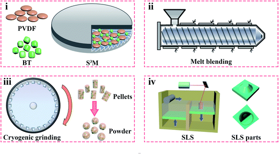 | ||
| Fig. 1 A schematic illustration of the process for the preparation and SLS processing of the PVDF/BaTiO3 composites. | ||
2.3 Characterization
| Xc = ΔHm/(1 − φ)ΔH0m × 100% | (1) |
| F(β) = Aβ/[(Kβ/Kα)Aα + Aβ] | (2) |
3. Results and discussion
3.1 The processability of the PVDF/BaTiO3 composite powder
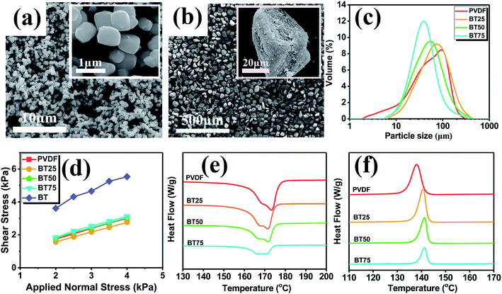
In order to achieve the uniform dispersion of BaTiO3 and good piezoelectric properties of the composites, nearly spherical tetragonal BaTiO3 particles (Fig. 2(a)) with an average particle size of 500 nm were selected as the piezoelectric reinforcement phase. SEM images of a composite powder prepared by solid state shear milling (S3M) and cryogenic grinding technology are shown in Fig. 2(b). Due to the strong shear force of the S3M equipment, the BaTiO3 particles were evenly dispersed in the PVDF matrix without agglomeration, which was extremely beneficial to the improvement of the piezoelectric performance. In addition, the prepared composite powder had an irregular block shape and a rough surface, which was conducive to forming a dense powder bed and fully absorbing the laser during SLS processing. SLS processing also had certain requirements regarding the particle size of the powder. A small particle size of the powder could easily cause electrostatic adsorption and agglomeration. While if the particle size was too large, it was difficult to obtain high dimensional deviation of the SLS parts. Therefore, the average particle size of the SLS powder should be in the range of 20–80 μm and the particle size distribution should be in the range of 1–200 μm. As shown in Fig. 2(c), the average particle sizes of PVDF and the PVDF/BaTiO3 powder were in the range of 40–60 μm and D90 was always less than 150 μm, meeting the requirements of SLS processing. The shear test results are shown in Fig. 2(d) and Table 1. The cohesion (C) and unconfined yield strength (σc) of BaTiO3 were 1.82 kPa and 8.48 kPa, respectively, confirming the large cohesive force between the BaTiO3 powder particles. The flow function (ff) of BaTiO3 was only 1.75, representing an extremely viscous flow, so BaTiO3 was a kind of powder particle with poor flowability. Therefore, the cohesion and unconfined yield strength of the composite powder gradually increased with the increase of the BaTiO3 content. This was due to the fact that the addition of BaTiO3 degraded the initial flowability of the powder. The flow functions were all between 4 and 10, representing viscous flow, confirming that PVDF had a good coating effect on BaTiO3. Even when the content of BaTiO3 reached 75 wt%, the composite powder still retained most of the flow characteristics of the PVDF powder. Other flowability parameters of the powder are shown in Fig. S1,† and were in good accordance with the shear test results. From the DSC curves in Fig. 2(e) and (f), the initial melting temperature (Tim), initial crystallization temperature (Tic) and sintering window (SW) were obtained and listed in Table 2. The sintering window (SW), representing the region between Tim and Tic of the polymer, was the selection range of the preheating temperature. A wide sintering window is beneficial to adjust the SLS processing parameters, effectively avoiding the warpage of the parts. PA11 and PA12 are the most widely used polymer materials for SLS. The sintering windows of PA11 and PA12 are usually in the range of 10–15 °C. The DSC results showed that the sintering windows of PVDF and the PVDF/BaTiO3 powder were always larger than 17 °C, making them suitable for SLS processing.| Sample | C, kPa | σc, kPa | ff | φi, ° | ε, g ml−1 |
|---|---|---|---|---|---|
| PVDF | 0.484 | 1.76 | 6.13 | 32.4 | 0.795 |
| BT25 | 0.384 | 1.35 | 7.82 | 30.7 | 0.954 |
| BT50 | 0.582 | 2.09 | 5.12 | 31.7 | 1.17 |
| BT75 | 0.616 | 2.24 | 4.52 | 32.7 | 1.35 |
| BaTiO3 | 1.82 | 8.48 | 1.75 | 43.6 | 1.14 |
| Sample | Tim (°C) | Tic (°C) | SW (°C) |
|---|---|---|---|
| PVDF | 160.7 | 141.5 | 19.2 |
| BT25 | 160.7 | 142.7 | 18.0 |
| BT50 | 160.1 | 142.9 | 17.2 |
| BT75 | 160.5 | 143.0 | 17.5 |
3.2 The morphology and crystallinity of the PVDF/BaTiO3 SLS parts
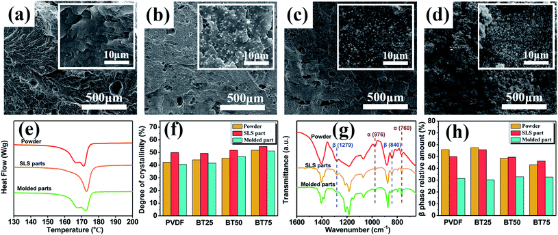
The cross sections of the PVDF and composite parts are shown in Fig. 3(a)–(d). With the increase of the BaTiO3 content, the porosity of the SLS parts gradually increased. This was because some of the BaTiO3 particles were exposed on the surface of the powder, which reduced the bonding effect of the powder in SLS processing. When the BaTiO3 content reached 75 wt%, the number of internal structural defects increased greatly. At this time, the tensile strength and elongation at break of the SLS parts were only 2.44 MPa and 0.75%, respectively (Fig. S2†), which could not meet the actual application requirements. The high crystallinity (Xc) and β phase relative amount (Kβ) were key to obtaining excellent conversion efficiency. However, different from traditional processing methods, SLS processing has a unique way of affecting the crystallization behavior of polymers and the understanding of the related mechanism is not clear enough. For comparison, PVDF/BaTiO3 molded parts were prepared using the SLS powder. The preparation process was as follows: the composite material was first hot pressed at 210 °C for 7 min, then cold pressed at room temperature for 10 min. In order to study the crystallization behavior of the composites during SLS processing, the crystal structures of the powder, SLS parts and molded parts were analyzed by DSC and FT-IR, as shown in Fig. 3(e)–(h). It was clear that due to the imperfect crystal structure in the powder and molded parts, the heating curves both showed double peaks. However, the heating curve of the SLS parts presented a narrow and sharp single peak. The reason was that in SLS processing, the single-layer powder underwent the stage of holding and cooling for several tens of minutes after laser sintering, so the crystal could grow well during this period. In addition, the crystallinity of the SLS parts was significantly higher than that of the powder and molded parts, also illustrating that the crystallization of the SLS parts was more perfect. The FT-IR results showed that the powder, SLS parts and molded parts all exhibited absorption peaks representing α (760 cm−1 and 976 cm−1) and β phase (840 cm−1 and 1279 cm−1). But different processing methods led to different Kβ. The Kβ of the SLS parts was close to that of the powder, but much higher than that of the molded parts. This was because the PVDF and PVDF/BaTiO3 powder prepared by this technical route had a relatively high Kβ, while the SLS processing only caused partial melting of the powder and was beneficial to the crystallization of PVDF. Therefore, the SLS parts could maintain the crystal structure of the powder to a large extent. In contrast, the powder was completely melted in the molding process and the crystal structure was completely destroyed. Because molding is a processing method with low stress field and it is difficult to induce β phase, the Kβ of the molded parts was much lower than that of the powder and SLS parts. In summary, the crystallinity and Kβ of the SLS parts both reached about 50%, which was the basis for obtaining excellent piezoelectric properties. It is worth noting that the BaTiO3 content had little effect on the crystallinity and Kβ of PVDF and the crystal structure of the composite parts was basically the same with the PVDF parts.3.3 The crystallization behaviors of the PVDF/BaTiO3 composite powder
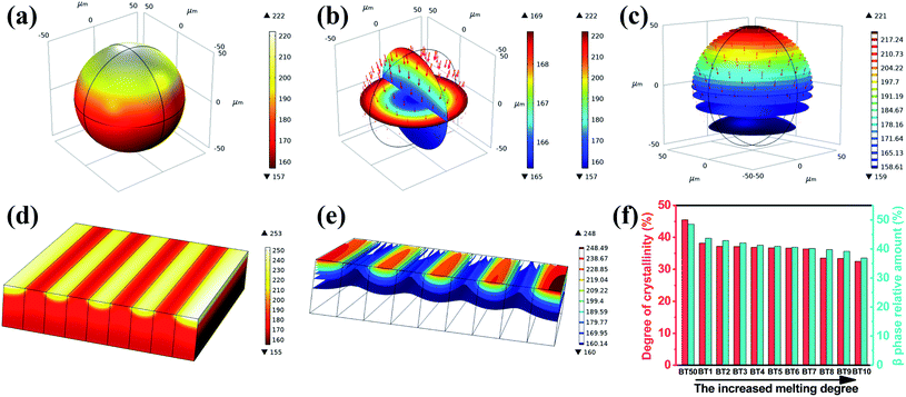
In order to further study the crystallization behavior of the powder in SLS processing, the heat transfer process of the powder particles and powder bed under laser irradiation was simulated by the finite element method, and the results are shown in Fig. 4(a)–(e). In the finite element analysis, the heat transfer mode of the “deposited beam power” in the “solid heat transfer” module was adopted. The incident laser power was 10 W. The thermal conductivity of the material was set to 0.2 W (m K)−1 and the density was 2492 kg m−3, which were derived from the characterization data of the composites. On the one hand, the powder was not completely melted under laser irradiation and the temperature of more than half of the particles was still lower than the melting point (170 °C). So the degree of crystal structure reconstruction after SLS processing was not high. On the other hand, in the process of laser sintering of the powder, the scanning distance between laser beams was 0.1 mm. So there were still some powder particles that were not completely melted, whose crystal structure only changed a little (Fig. 4(d) and (e)). Therefore, the crystal structure of the parts was similar to that of the powder due to the unique processing method of SLS. In order to confirm the experiment and the finite element simulation results, the following confirmatory experiments were carried out: the gradual melting of the composites was realized by heating the bottom of the composite powder bed with a certain height. The powder with different heights (i.e. different degrees of melting) were characterized by DSC and FT-IR, respectively (Fig. S3†), and the relationship between the crystal structure and the melting degree was established, as shown in Fig. 4(f). Because the powder bed was heated from the bottom, the temperature and the melting degree of the powder increased with the decrease of the height. Meanwhile, the crystallinity and Kβ gradually decreased with the increase of the crystal structure reconstruction degree. However, the polymer melt could not be induced to form the polar crystalline phase (β phase) only relying on bottom heating. So the crystallinity and Kβ of the composites with a high melting degree were obviously lower than those of the composite powder before melting. Combined with the finite element simulation results, the melting degree of the powder after laser irradiation was closer to that of the upper part of the powder bed in the confirmatory experiment, so the crystallinity and Kβ of the SLS parts could reach about 50%, which was similar to that of the powder.3.4 The piezoelectric performance of the PVDF/BaTiO3 composites and cymbal parts
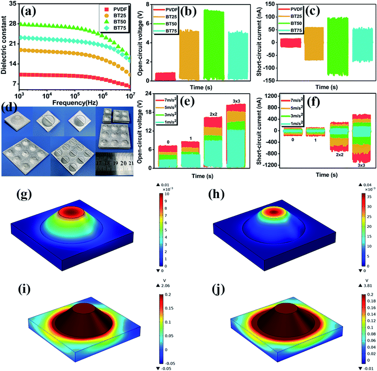
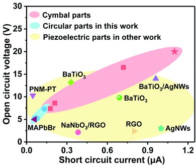
The frequency-dependent dielectric response of the PVDF and PVDF/BaTiO3 SLS parts is shown in Fig. 5(a). Due to the excellent dielectric properties of BaTiO3, the dielectric constant of the composites increased first and then decreased with the increase of the BaTiO3 content, which was conducive to the improvement of the polarization efficiency and endowed the SLS parts with good piezoelectric properties. Specifically, the dielectric constant of BT50 reached the maximum value of 27.8 at 1000 Hz, which was about 2.7 times than that of PVDF. The ferroelectric P–E hysteresis curve of BT50 is shown in Fig. S4.† The remnant polarization (Pir) and coercive field (Eic) of BT50 were 70.6 μC m−2 and 2.83 kV cm−1, respectively, which exhibited a good polarization effect. However, when the BaTiO3 content was 75 wt%, the dielectric properties of the composites decreased obviously because of a large number of structural defects. The open circuit voltage and short circuit current of the SLS parts under the impact of a linear motor are compared in Fig. 5(b) and (c). The results showed that the piezoelectric properties of the SLS parts also increased first and then decreased with the increase of the BaTiO3 content. When the BaTiO3 content was 50 wt%, the open circuit voltage and short circuit current of the SLS parts reached the maximum, namely 7.3 V and 132.2 nA, respectively. The piezoelectric strain coefficient (d33) of BT50 was 2.0 pC N−1, which was measured by quasi-static d33 apparatus (ZJ-3A). Due to the high BaTiO3 content, the bonding effect of the BT75 powder in SLS processing was poor, making it difficult for the BT75 parts to effectively transfer stress and deform. So the piezoelectric performances of the BT75 parts were worse than those of the BT50 parts. In addition, it was gratifying that the piezoelectric properties of the SLS parts were better than those of the molded parts due to the higher β content (Fig. S5†), which proved the great potential of SLS processing in preparing piezoelectric devices. Based on the PVDF/50 wt% BaTiO3 composites, one-piece cymbal structure piezoelectric parts with excellent stress-to-electricity conversion efficiency were prepared by SLS processing. As shown in Fig. 5(d), the cymbal parts were composed of two identical fittings with a cymbal cavity, drawing on the mortise–tenon connection in traditional Chinese carpentry technology, and no adhesive was used. In contrast, the reference parts with the same appearance but without the cymbal cavity were designed. In order to obtain better piezoelectric properties, the above-mentioned cymbal structure models were connected in series in the form of 2 × 2 and 3 × 3 arrays, respectively. For convenience, the reference parts were named as “0”, the cymbal parts as “1”, 2 × 2 series connection parts as “2 × 2”, and 3 × 3 series connection parts as “3 × 3”. The dimensional parameters of the “0”, “1”, “2 × 2” and “3 × 3” parts were 14 × 14 × 8 mm, 14 × 14 × 8 mm, 28 × 28 × 8 mm and 42 × 42 × 8 mm, respectively. The open circuit voltage and short circuit current of these parts under different acceleration impacts of the linear motor are shown in Fig. 5(e) and (f). Forces of 5.5, 10.0, 15.3 and 24.5 N were applied to the parts subject to impact acceleration rates of 1, 3, 5 and 7 m s−2, respectively. Compared with the reference parts, the cymbal parts were endowed with more excellent piezoelectric properties. This was because the unique cymbal cavity could improve the deformation ability of the parts and effectively transfer the stress. The increased deformation could act on the dipole moments of the composites to promote the separation of the positive and negative charge centers and generate a larger displacement current. In addition, when the external impact changed, the piezoelectric responsiveness of the cymbal parts was better, which was also benefitted from the structural characteristics of the cymbal cavity. The current output and responsiveness of the series connected parts were further enhanced. Under the impact of 7 m s−2 acceleration, the open circuit voltage and short circuit current of the 3 × 3 parts could reach 20 V and 1.1 μA, respectively. In order to quantitatively describe the piezoelectric conversion efficiency, we calculated the output power of the circular parts and cymbal parts under the impact of 5 m s−2 acceleration. As shown in Fig. S6,† the output powers of the 2 × 2 and 3 × 3 cymbal parts were significantly higher than those of the circular parts, proving that the design and construction of the cymbal structure could indeed improve the piezoelectric conversion efficiency. The finite element simulation results of the deformation and output voltage generated by the cymbal parts and the reference part under the same external force are shown in Fig. 5(g)–(j). In the finite element analysis, the “solid mechanics” module was adopted. The boundary constraints of the model were carried out according to the actual test conditions and a stress of 10 N was applied to the upper surface. The piezoelectric strain coefficient (d33) of the material was set to 2.0 pC N−1, the density was 2492 kg m−3 and the dielectric constant was 28.52, which were derived from the characterization data of the composites. When the cymbal parts were subjected to an external force, they could diffuse the force in time, and prevent stress concentration, promoting a higher response to the external force, and could effectively transform the external force into deformation. In addition, in the process of stress-to-electricity conversion, the cymbal part could produce axial and radial deformation at the same time (Fig. 5(j)), so the piezoelectric coefficients from multiple directions were fully utilized. The excellent piezoelectric output performances of the cymbal parts were the result of the superposition of the piezoelectric properties in the two directions.The piezoelectric properties of the cymbal parts and other reported parts are compared in Fig. 6. The piezoelectric composites based on PVDF and its modified materials exhibited good conversion efficiency; for example, PVDF/PNM-PT,46 PVDF-TrFE/BaTiO3,47,48 PVDF/BaTiO3/AgNWs,49 PVDF/NaNbO3/RGO,50 PVDF/MAPbBr,51 PVDF-TrFE/RGO,52 PVDF/AgNWs,53 etc. By comparison, the piezoelectric performances of the as-prepared 3 × 3 cymbal parts were further improved, and they had great application prospects in the field of sensing and energy capture.
4. Conclusions
In summary, a novel PVDF/BaTiO3 piezoelectric composite material suitable for SLS processing was prepared by solid state shear milling technology. High content filled BaTiO3 particles with noble dielectric and piezoelectric properties were evenly dispersed into PVDF via the strong shearing force generated from S3M equipment. The obtained SLS parts were endowed with higher content of electroactivated β phase (up to 56%). What's more, the structurally designed one-piece cymbal part exhibited the performance characteristics of amplifying stress and coupling the piezoelectric coefficients from multiple directions. The open circuit voltage and short circuit current could reach 20 V and 1.1 μA, respectively, which were better than those of the composites reported in other work. This work not only introduced a new manufacturing method for polymer/ceramic piezoelectric composite materials, but also demonstrated a novel piezoelectric performance optimization strategy via 3D structural design.Conflicts of interest
There are no conflicts to declare.Acknowledgements
This work was kindly supported by the National Natural Science Foundation of China (51933007, 51673123 and 52003174), the National Key R&D Program of China (No. 2017YFE0111500) and the Program for Featured Directions of Engineering Multidisciplines of Sichuan University (No. 2020SCUNG203). We would like to thank the College of Electronics and Information Engineering of Sichuan University for providing COMSOL software.References
- R. Lay, G. S. Deijs and J. Malmström, RSC Adv., 2021, 11, 30657–30673 RSC.
- Z. Duan, Y. Jiang, Q. Huang, S. Wang, Y. Wang, H. Pan, Q. Zhao, G. Xie, X. Du and H. Tai, Smart Mater. Struct., 2021, 30, 055012 CrossRef CAS.
- C. Yan, Y. Gao, S. Zhao, S. Zhang, Y. Zhou, W. Deng, Z. Li, G. Jiang, L. Jin, G. Tian, T. Yang, X. Chu, D. Xiong, Z. Wang, Y. Li, W. Yang and J. Chen, Nano Energy, 2019, 10, 104235 Search PubMed.
- X. Zhang, H. Lin, H. Shang, J. Xu and W. Huang, SusMat, 2021, 1, 105–126 CrossRef.
- D. Zhang, B. Fan, L. Ying, N. Li, C. J. Brabec, F. Huang and Y. Cao, SusMat, 2021, 1, 4–23 CrossRef.
- N. Sezer and M. Koç, Nano Energy, 2021, 80, 105567 CrossRef CAS.
- J. Guo, M. Nie and Q. Wang, RSC Adv., 2021, 11, 1182–1186 RSC.
- Z. Li, G. Zhu, R. Yang, A. C. Wang and Z. L. Wang, Adv. Mater., 2010, 22, 2534–2537 CrossRef CAS PubMed.
- X. Cheng, X. Xue, Y. Ma, M. Han, W. Zhang, Z. Xu, H. Zhang and H. Zhang, Nano Energy, 2016, 22, 453–460 CrossRef CAS.
- Q. Zhao, L. Yang, K. Chen, Y. Ma, Q. Peng, H. Ji and J. Qiu, Compos. Sci. Technol., 2020, 199, 108330 CrossRef CAS.
- Y. Li, K. Zhang, M. Nie and Q. Wang, Ind. Eng. Chem. Res., 2019, 58, 22273–22282 CrossRef CAS.
- X. Liu, Y. Shang, J. Zhang and C. Zhang, ACS Appl. Mater. Interfaces, 2021, 13, 14334–14341 CrossRef CAS PubMed.
- L. Song, R. Dai, Y. Li, Q. Wang and C. Zhang, ACS Sustainable Chem. Eng., 2021, 9, 7561–7568 CrossRef CAS.
- H. Cui, R. Hensleigh, D. Yao, D. Maurya, P. Kumar, M. G. Kang, S. Priya and X. Zheng, Nat. Mater., 2019, 18, 234–241 CrossRef CAS PubMed.
- J. Kim, J. Oh, S. Lim, J. Y. Sim, J. S. Jeon, K. No, S. Park and S. Hong, Nano Energy, 2019, 55, 348–353 CrossRef.
- C. Yang, N. Chen, X. Liu, Q. Wang and C. Zhang, RSC Adv., 2021, 11, 20662–20669 RSC.
- C. Shuai, G. Liu, Y. Yang, F. Qi, S. Peng, W. Yang, C. He, G. Wang and G. Qian, Nano Energy, 2020, 74, 104825 CrossRef CAS.
- L. Song, Z. Huang, S. Guo, Y. Li and Q. Wang, ACS Appl. Mater. Interfaces, 2021, 13, 37252–37261 CrossRef CAS PubMed.
- Y. Jin, N. Chen, Y. Li and Q. Wang, RSC Adv., 2020, 10, 20405–20413 RSC.
- C. Ribeiro, C. M. Costa, D. M. Correia, J. Nunes-Pereira, J. Oliveira, P. Martins, R. Goncalves, V. F. Cardoso and S. Lanceros-Mendez, Nat. Protoc., 2018, 13, 681–704 CrossRef CAS PubMed.
- V. S. Bhugra, M. Maddah, G. V. Williams, N. Plank and T. Nann, RSC Adv., 2019, 9, 31233–31240 RSC.
- P. Li, J. W. Zhai, B. Shen, S. J. Zhang, X. L. Li, F. Y. Zhu and X. M. Zhang, Adv. Mater., 2018, 30, 1705171 CrossRef PubMed.
- D. Tian, P. Chen, X. Yang and B. Chu, Ceram. Int., 2021, 47, 17262–17267 CrossRef CAS.
- C. Yang, S. Song, F. Chen and N. Chen, ACS Appl. Mater. Interfaces, 2021, 13, 41723–41734 CrossRef CAS PubMed.
- S. Song, Y. Li, S. Bai and Q. Wang, Chem. Eng. J., 2021, 415, 129035 CrossRef CAS.
- F. Qi, N. Chen and Q. Wang, Mater. Des., 2017, 131, 135–143 CrossRef CAS.
- N. Chamankar, R. Khajavi, A. A. Yousefi, A. Rashidi and F. Golestanifard, Ceram. Int., 2020, 46, 23567–23581 CrossRef CAS.
- W. Ren, Z. Li, Y. Chen, H. Gao, W. Yang, Y. Wang and Y. Luo, Macromol. Mater. Eng., 2019, 304, 1800491 CrossRef.
- P. Eltouby, I. Shyha, C. Li and J. Khaliq, Ceram. Int., 2021, 47, 17813–17825 CrossRef CAS.
- S. Yi, W. Zhang, G. Gao, H. Xu and D. Xu, Ceram. Int., 2018, 44, 10940–10944 CrossRef CAS.
- S. Yang, W. Li, S. Bai and Q. Wang, J. Mater. Chem. C, 2018, 6, 11209–11218 RSC.
- Y. Li, P. Huang, S. Guo and M. Nie, J. Cleaner Prod., 2020, 272, 122694 CrossRef CAS.
- H. Zhang, Y. Zhu and L. Li, RSC Adv., 2020, 10, 3391–3401 RSC.
- P. Liu, W. Chen, Y. Jia, S. Bai and Q. Wang, Mater. Des., 2017, 134, 121–131 CrossRef CAS.
- C. Zhang, Y. Li, W. Kang, X. Liu and Q. Wang, SusMat, 2021, 1, 127–147 CrossRef.
- Y. Yuan, W. Wu, H. Hu, D. Liu, H. Shen and Z. Wang, RSC Adv., 2021, 11, 1984–1991 RSC.
- D. Xu, H. Zhang, L. Pu and L. Li, Compos. Sci. Technol., 2020, 192, 108108 CrossRef CAS.
- S. Song, Y. Li, Q. Wang and C. Zhang, Composites, Part A, 2021, 147, 106452 CrossRef CAS.
- Z. Guo, E. Nilsson, M. Rigdahl and B. Hagström, J. Appl. Polym. Sci., 2013, 130, 2603–2609 CrossRef CAS.
- W. U. A. Yee, K. Masaya, Y. E. Liu and L. U. Xuehong, Polymer, 2007, 48, 512–521 CrossRef CAS.
- H. Abdolmaleki and S. Agarwala, Polymers, 2020, 12, 2430 CrossRef CAS PubMed.
- Y. Yang, H. Pan, G. Xie, Y. Jiang, C. Chen, Y. Su, Y. Wang and H. Tai, Sens. Actuators, A, 2020, 301, 111789 CrossRef CAS.
- J. Jiang, S. Tu, R. Fu, J. Li, F. Hu, B. Yan, Y. Gu and S. Chen, ACS Appl. Mater. Interfaces, 2020, 12, 33989–33998 CrossRef CAS PubMed.
- Z.-z. He, X. Yu, J.-h. Yang, N. Zhang, T. Huang, Y. Wang and Z.-w. Zhou, Composites, Part A, 2018, 104, 89–100 CrossRef CAS.
- L. Wu, N. Luo, Z. Xie, Y. Liu, F. Chen and Q. Fu, Compos. Sci. Technol., 2020, 190, 108046 CrossRef CAS.
- C. Li, P. Hu, H. Meng and Z. Jiang, J. Solution Chem., 2016, 45, 67–80 CrossRef CAS.
- S. Siddiqui, D.-I. Kim, L. T. Duy, M. T. Nguyen, S. Muhammad, W.-S. Yoon and N.-E. Lee, Nano Energy, 2015, 15, 177–185 CrossRef CAS.
- X. Chen, X. Li, J. Shao, N. An, H. Tian, C. Wang, T. Han, L. Wang and B. Lu, Small, 2017, 13, 1604245 CrossRef PubMed.
- B. Dudem, D. H. Kim, L. K. Bharat and J. S. Yu, Appl. Energy, 2018, 230, 865–874 CrossRef CAS.
- H. H. Singh, S. Singh and N. Khare, Compos. Sci. Technol., 2017, 149, 127–133 CrossRef CAS.
- A. Sultana, M. M. Alam, P. Sadhukhan, U. K. Ghorai, S. Das, T. R. Middya and D. Mandal, Nano Energy, 2018, 49, 380–392 CrossRef CAS.
- R. M. Habibur, U. Yaqoob, S. Muhammad, A. S. M. I. Uddin and H. C. Kim, Mater. Chem. Phys., 2018, 215, 46–55 CrossRef CAS.
- D. Mandal, K. Henkel and D. Schmeißer, Phys. Chem. Chem. Phys., 2014, 16, 10403–10407 RSC.
Footnote |
| † Electronic supplementary information (ESI) available. See DOI: 10.1039/d1ra06915b |
| This journal is © The Royal Society of Chemistry 2021 |

