 Open Access Article
Modulating the stacking modes of nanosized metal–organic frameworks by morphology engineering for isomer separation†
Ming
Xu‡
ab,
Sha-Sha
Meng‡
a,
Peiyu
Cai
b,
Wen-Qi
Tang
a,
Yun-Dong
Yin
a,
Joshua A.
Powell
b,
Hong-Cai
Zhou
 *bc and
Zhi-Yuan
Gu
 *a
*a
aJiangsu Key Laboratory of Biofunctional Materials, Jiangsu Collaborative Innovation Center of Biomedical Functional Materials, College of Chemistry and Materials Science, Nanjing Normal University, Nanjing, 210023, China. E-mail: guzhiyuan@njnu.edu.cn
bDepartment of Chemistry, Texas A&M University, College Station, TX 77843-3255, USA. E-mail: zhou@chem.tamu.edu
cDepartment of Materials Science and Engineering, Texas A&M University, College Station, Texas 77842, USA
First published on 3rd February 2021
Abstract
Modulating different stacking modes of nanoscale metal–organic frameworks (MOFs) introduces different properties and functionalities but remains a great challenge. Here, we describe a morphology engineering method to modulate the stacking modes of nanoscale NU-901. The nanoscale NU-901 is stacked through solvent removal after one-pot solvothermal synthesis, in which different morphologies from nanosheets (NS) to interpenetrated nanosheets (I-NS) and nanoparticles (NP) were obtained successfully. The stacked NU-901-NS, NU-901-I-NS, and NU-901-NP exhibited relatively aligned stacking, random stacking, and close packing, respectively. The three stacked nanoscale NU-901 exhibited different separation abilities and all showed better performance than bulk phase NU-901. Our work provides a new morphology engineering route for the modulation of the stacking modes of nano-sized MOFs and improves the separation abilities of MOFs.
Introduction
Nanomaterial stacking has attracted significant research interest in recent years, providing a new modulation method for obtaining functional materials with tunable structures and properties. This led to the discovery of the record-high superconduction of stacked graphene multilayers with magic angle and tunable catalytic properties of MoS2.1–5 Nano-sized metal–organic frameworks (MOFs) have been attracting a lot of attention because nano-MOFs combine the advantages of nanomaterials and MOFs, such as uniform size and morphology, high porosity and designable molecular structures.6–8 Typically, nano-MOFs consist of nanoscale three-dimensional (3D) MOF nanoparticles and two-dimensional (2D) MOF nanosheets. Meanwhile, the stacking of nano-MOFs is also of great importance, leading to favorable or adverse properties, which require further modulation. On the one hand, the close packing of nanoparticles usually results in a reduced number of exposed active sites, leading to low performance in catalysis. On the other hand, aligned 2D MOF nanosheet stacking exhibits great separation selectivity for isomers.9However, the modulation of stacking modes of nano-MOFs remains a big challenge. Controlling the size and morphology of MOFs is an ongoing challenge, as the rate of nucleation and growth of MOFs must be well controlled through careful selection of metal salts, modulators, reagent concentrations, heating methods, temperature, and time for the synthesis.10–12 Sometimes, even the same synthetic conditions for structurally related MOFs will result in different crystal sizes and morphologies of the MOF products.13,14 Furthermore, to date, there is still a lack of operational, repetitive, and robust methods to modulate the stacking modes of nano-MOFs because of their extremely small size and the complicated interactions between nano-MOF particles.15,16 Thus, developing suitable methods for synthesizing nanoscale MOFs and modulating their stacking modes is highly important.
Here, a zirconium-based MOF, NU-901, was chosen as a model since it contains strong coordination bonds between the Zr clusters and the carboxylic acids of the ligand based on the hard–soft acid–base theory, leading to a stable MOF structure.17–19 To investigate the stacking modes, nano-NU-901 with three different morphologies (ultrathin nanosheets (NU-901-NS), interpenetrated nanosheets (NU-901-I-NS), and nanoparticles (NU-901-NP)) have been successfully synthesized using water and monotopic acids as modulators (Scheme 1). The kinetically preferred NU-901-NS and NU-901-I-NS were first reported through the fine-tuning of the ratio of H2O to monotopic acid by synergistically promoting the partial hydrolysis of Zr4+ and reducing the surface energy of nanosheets.20–22 All three morphologies of NU-901 stacked after removing the solvent molecules. Fluorescence experiments demonstrated that the stacked NU-901-NS, NU-901-I-NS, and NU-901-NP exhibited relatively aligned stacking, random stacking, and close packing, respectively. Meanwhile, N2 adsorption demonstrated that the close packed NU-901-NP minimized inter-particle voids and displayed more uniform pore size distribution than NU-901-NS and NU-901-I-NS.
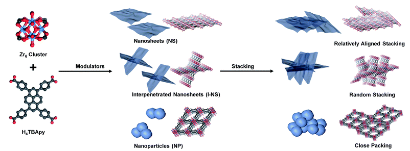 | ||
| Scheme 1 Synthesis of NU-901 with different morphologies using AA, BA, HCl, and water as modulators and the different stacking modes of the three nanoscale NU-901. | ||
Further applications of the three stacked nano-NU-901 materials as gas chromatographic (GC) stationary phases were explored and compared with bulk NU-901. Because of the different pore sizes and distributions from the different stacking modes, the three stacked nano-NU-901 exhibited different separation abilities, among which NU-901-NP showed the highest resolution. It was worth noting that all three nano-NU-901 stacked materials exhibited better separation abilities than bulk NU-901 due to the reduced diffusion barrier and uniform coating onto the capillary column.23,24 Furthermore, a rare para-isomer selectivity was observed in the separation of disubstituted benzene isomers. This morphology engineering approach provides an opportunity to enhance the performance of MOFs in separations by modulating the stacking modes of nano-sized MOFs.
Results and discussion
Synthetic considerations
NU-901 with different morphologies (bulk NU-901, NU-901-NS, NU-901-I-NS, and NU-901-NP) was prepared by varying the identity of the monotopic acid modulator and the ratios of the acid to water (Table S1†). For example, NU-901-NS was synthesized by using 120 μL acetic acid (AA) as a modulator with 50 μL H2O. The 20 mL vial was heated at 120 °C for 24 h after all reagents were dissolved in 2 mL DMF. The resulting products were collected by centrifugation and washed with fresh N,N-dimethylformamide (DMF), and ethanol (EtOH) three times, respectively. Full details of the synthesis and washing procedures are provided in the ESI.† A detailed description of the characterization techniques, such as powder X-ray diffraction (PXRD), nitrogen sorption, thermogravimetric analysis (TGA), transmission electron microscopy (TEM), scanning electron microscopy (SEM), high-resolution transmission electron microscopy (HRTEM), atomic force microscopy (AFM) and high angle annular dark field (HAADF) imaging are also provided in the ESI.†Harnessing acetic acid, benzoic acid, water and HCl as modulators for the synthesis of nano-NU-901 with different morphologies
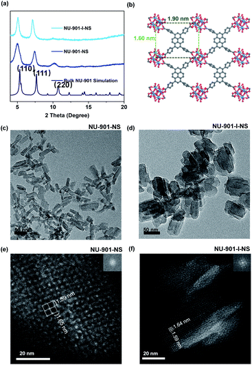
For the synthesis of 2D ultrathin NU-901-NS with high yield, the “bottom-up” method was chosen to directly employ molecular building blocks in one-pot solvothermal reactions.25 Usually, surfactants are needed to reduce the high surface energy in order to avoid the formation of the thermodynamically stable 3D MOFs.26 However, the surfactants are usually difficult to remove, which leads to reduced active sites on the nanosheets. Here, we developed a highly robust, bottom-up method using water and monotopic acids as modulators, which required no surfactants. This modulation provides both thermodynamic and kinetic control, simultaneously. Water was chosen here to achieve supersaturation of the building blocks in the reaction mixture through promoting the partial hydrolysis of Zr4+ and creating more Zr6 clusters (Zr6(μ3-O)4(μ3-OH)4).20–22 This supersaturation process allows the nucleus of the crystal to tolerate higher surface energy and thus form nanosheets rather than bulk 3D crystals. Meanwhile, monotopic modulators, including benzoic acid (BA) and AA, were utilized to cap the surface of nanosheets, reducing their surface energy. In addition, the molar ratio of building blocks and each modulator (water and AA/BA) was used to synergistically control the hydrolysis rate of Zr4+ and the modulator capping rates on the nanosheets. Through fine-tuning, fast precipitation of the kinetically preferred products could be achieved.According to the previous conception, NU-901-NS has been successfully synthesized. Meanwhile, other morphologies, such as NU-901-I-NS have also been discovered (Scheme 1). Typically, with 120 μL AA and 50 μL water as modulators, NU-901-NS with a dimension of approximately 20 × 60 nm was obtained (Fig. 1c). With the volume of water (50 μL) fixed, when more AA (from 120 μL to 600 μL) was added into the reaction mixture, the morphology of NU-901-NS would change to interpenetrated nanosheet structures and eventually become MOF particles (Fig. S1†). A similar phenomenon could also be found using BA as a modulator with 50 μL water (Fig. S2†). With 120 mg BA and 50 μL water as modulators, the interpenetrated nanosheet was successfully obtained as well, named NU-901-I-NS (Fig. 1d). We supposed that with more monotopic acid (BA or AA) modulators, the hydrolysis of Zr4+ would be slowed down and more BA- or AA-capped Zr6 clusters would be generated, hampering the precipitation of the kinetically preferred product nanosheets. The increased concentration of modulators finally led to thermodynamically stable 3D NU-901 particles. When the modulator concentration was in between the two conditions, interpenetrated nanosheets were produced. The hypothesis could also be supported by the reverse product sequence obtained from increasing the water volume with a fixed amount of AA modulator (Fig. S3†). With more water (from 0 μL to 80 μL) in the synthesis mixture, the material morphology changed from NU-901 particles to interpenetrated nanosheets and finally became nanosheet structures (Fig. S3†). The HRTEM and SEM images of all the materials are exhibited in the ESI† (Fig. S4 and S5†). It is worthwhile to note that because of the small size and thickness of these materials, it is hard to observe the “sheet” morphologies in SEM images. However in HRTEM images the different morphologies from nanosheets to interpenetrated nanosheets can be obviously distinguished (Fig. S4†).
PXRD experiments were performed on all synthesized materials. The first two main peaks are assigned as the (110) and (111) planes, respectively, which are consistent with the simulated PXRD pattern of NU-901 (Fig. 1a and S6–S10†).27 The absence of specific PXRD peaks results from preferred orientations and the obviously broadened peaks result from the small particle sizes of the obtained materials.28 The average thickness of NU-901-NS is determined from the AFM images (Fig. S11†) to be 4.33 nm, which indicates that the as-synthesized NU-901-NS has about 5 layers. To further investigate the structure of the synthesized materials, the HAADF images of NU-901-NS and NU-901-I-NS were obtained (Fig. 1 and S12†). As shown in Fig. 1e and f, the adjacent Zr6 clusters form reticular architectures with the edge distances of ∼1.59 nm and ∼1.64 nm, respectively. The measured distances are a bit smaller than those of the simulated crystal structures in Fig. 2b (∼1.60 nm and ∼1.90 nm). This phenomenon might refer to the framework shrinking without guest molecules as well as the distortion and homogenized distribution of rectangular TBApy4− ligands.
To obtain uniform NU-901 nanoparticles, the strong acid modulator HCl was chosen because the low acidity of the previous monotopic carboxylic acids led to inhomogeneity, irregularity, and large particle size (Fig. S1–S3†). Here, unlike the monotopic carboxylic acids, the HCl modulator could protonate the Zr6 clusters and accelerate the precipitation of the thermodynamically stable 3D NU-901.29,30 After tuning the amount of the added HCl, NU-901-NP was obtained by using 120 μL HCl and 50 μL of water as modulators. The PXRD pattern in Fig. S6† exhibits three peaks which are assigned to the (110), (111) and (220) planes respectively (Fig. S8†). This is consistent with the simulated PXRD pattern of bulk NU-901. Similar to NU-901-NS and NU-901-I-NS, the broadened peaks might result from the small particle size.28 It is not easy to describe the shape of NU-901-NP from the TEM image in Fig. S13,† because the particles are much smaller than those of the bulk NU-901 shown in Fig. S14† and aggregate very easily. We hypothesize that the aggregation is attributed to possible coordination interactions or weak intermolecular interactions between nanoparticles because there are no carboxylic acids as capping molecules.
BET and fluorescence characterization of stacked nano-NU-901 with different morphologies
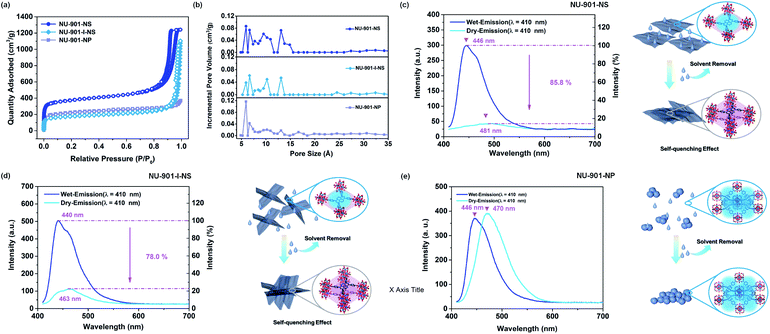
Taking advantage of the strong fluorescence and the self-quenching effect of the TBApy4− linkers, the stacking of the framework materials was examined through probing their fluorescence before and after solvent removal.31,32 As shown in Fig. 2c, NU-901-NS exhibits strong fluorescence. However, following solvent removal, the emission intensity of NU-901-NS decreases significantly (a reduction of ∼85.8%), and the emission peak shifts from 446 nm to 481 nm. This decreased and redshifted fluorescence from the self-quenching effect of the TBApy4− ligand indicates that the layers of NU-901-NS are stacked close to each other. A similar phenomenon can also be observed in NU-901-I-NS after solvent removal, which illustrates the coagulation of NU-901-I-NS. It is worth noting that the redshift and reduction in the intensity of the fluorescence for NU-901-I-NS are less than those of NU-901-NS after solvent removal. This demonstrates that the flat surface of NU-901-NS leads to the relatively aligned stacking, maximizing the quenching effect of TBApy4− linkers (Fig. 1e and 2c). Meanwhile, the interpenetrated structure of NU-901-I-NS impairs the aligned stacking compared to NU-901-NS, thus leading to a smaller decrease in intensity and redshift of the fluorescence. The phenomenon is also supported by the stacking results obtained from the HRTEM and HAADF images (Fig. 1c–f and S12†).Interestingly, in contrast to NU-901-NS and NU-901-I-NS, the emission intensity of NU-901-NP exhibits almost no difference before and after solvent removal, although the emission peak redshifts from 446 nm to 470 nm (Fig. 2e). The red-shift of the fluorescence illustrates that NU-901-NP coagulates much more significantly after solvent removal. However, even if the nanoparticles stack closely, the emission intensity shows almost no difference, demonstrating that the TBApy4− ligands inside NU-901-NP are isolated by their 3D net-structures, minimizing the self-quenching effects.31
The N2 adsorption isotherms were also recorded to characterize the pores of NU-901-NS, NU-901-I-NS, and NU-901-NP after the stacking process. As shown in Fig. 2a and b, both the Brunauer–Emmett–Teller (BET) surface area and pore volume of NU-901-I-NS (568.60 m2 g−1 and 1.01 m3 g−1) are much lower than those of NU-901-NS (1202.09 m2 g−1 and 1.86 m3 g−1). The different BET surface areas and pore volumes result from the different stacking modes of these two materials after solvent removal (Fig. 2c and d). The relatively aligned stacking of NU-901-NS can form more regular pores around 6 Å, while the random stacking of NU-901-I-NS reduces its porosity. The high N2 adsorption at P/P0 between 0.9 and 1.0 demonstrates that there are macropores in both stacked NU-901-NS and NU-901-I-NS, which belong to the inter-nanosheet voids formed from the stacking procedure. Moreover, there is a H2 type hysteresis loop in the N2 adsorption–desorption isotherms of NU-901-NS, illustrating that the desorption branch may depend on network and/or “ink bottle” effects.33 However, in NU-901-NP, there is almost no additional N2 adsorption at P/P0 between 0.9 and 1.0, indicating that the stacked NU-901-NP has minimized inter-particle voids. Furthermore, the BET surface area of NU-901-NP (726.62 m2 g−1) is lower than that of NU-901-NS but somewhat higher than that of NU-901-I-NS, which results from the close packing of the nanoparticles. In addition, the pore size distribution of NU-901-NP is significantly more uniform than that of the other two materials. The main pore sizes for NU-901-NP range between ∼5.9 Å and 6.7 Å, while the main pore sizes for NU-901-NS and NU-901-I-NS range from ∼5.0 Å to 15.1 Å (Fig. 2b). This illustrates that the pores of NU-901-NS and NU-901-I-NS are mainly formed from stacking, while the pores of NU-901-NP originate from its pristine network structure.
Separation performance of stacked nano-NU-901 with different morphologies for isomer separation
Because the different stacking modes of the three nano-NU-901 can form different pore environments, we tried to compare their separation abilities as GC stationary phases. First, NU-901-NS, NU-901-I-NS, and NU-901-NP were coated on the inner wall of capillary GC columns, resulting in the uniform layer(s) of the three materials, respectively (Fig. 3 and S15†). After the coating process, these capillary columns were aged at 250 °C for 180 min according to their thermal stabilities from the TGA results (Fig. S16†). For comparison, the bulk NU-901 was also coated on another capillary column, but with an uneven coating (Fig. 3a). The loading quantity of NU-901-NS, NU-901-I-NS, NU-901-NP, and bulk NU-901 on each capillary GC column (15 m) was calculated to be 1.2, 1.2, 1.1, and 1.2 mg, respectively (Fig. S17†). Then, the columns coated with the above three nano-NU-901 materials with different morphologies and bulk NU-901 were employed to separate octane, nonane, chlorotoluene, and ethyltoluene isomers, respectively (Fig. 4). For most of the isomer pairs, all three nano-NU-901 materials achieved better separation resolution (Rs) than bulk NU-901 materials (Table S2†). Meanwhile, NU-901-NP exhibited the best separation ability of the three stacked nanomaterials. This phenomenon is due to the nanomaterials containing different pore sizes and alignments as a consequence of their different stacking modes. The close packing of NU-901-NP with minimized inter-particle voids and uniform pore size distribution leads to the highest separation ability. Conversely, the relatively lower performance of NU-901-NS and NU-901-I-NS compared to NU-901-NP results from the random pores created by the stacking procedure. The random stacking of NU-901-I-NS reduces its porosity and pore volume, which hinders the diffusion of the analytes, leading to the relatively lower separation ability. Furthermore, the relatively aligned stacking of NU-901-NS creates higher porosity and more regular micropores (∼6 Å) than that of NU-901-I-NS, leading to better separation ability.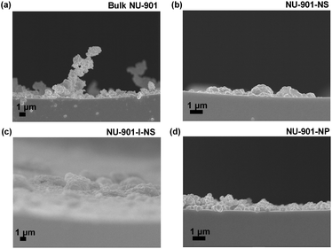 | ||
| Fig. 3 The SEM images of stacked (a) bulk NU-901, (b) NU-901-NS, (c) NU-901-I-NS and (d) NU-901-NP coated capillary column with a cross-sectional view. | ||
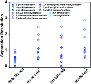 | ||
| Fig. 4 Separation resolution for different isomers on the capillary columns coated with stacked NU-901 with different morphologies. | ||
Although bulk NU-901 has a similar micropore environment to NU-901-NP, the separation ability is inferior. As shown in Fig. 4, 5a, and S19,† the bulk NU-901 shows almost no separation ability for isomers with very similar boiling points (such as chlorotoluene and nonane isomers), although linear alkane homologous compounds can be separated (Fig. S18†). We believe the poor performance of bulk NU-901 results from the large particle size. On the one hand, it enhances the molecular diffusion barrier inside the bulk NU-901 crystals. On the other hand, the large particle size of bulk NU-901 makes it harder to uniformly coat the capillary column walls, which also enhances the diffusion barrier of analytes inside the columns (Fig. 3a), which enhances the Eddy diffusion (A) term in the Van Deemter equation as well as reduces the theoretical plate number (N), leading to the low separation ability (NNU-901-NP = 1127 plates per m, Nbulk NU-901 = 419 plates per m (flow rate = 0.1 mL min−1)).
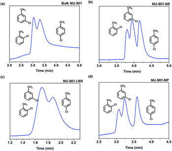 | ||
| Fig. 5 Gas chromatograms using stacked (a) bulk NU-901, (b) NU-901-NS, (c) NU-901-I-NS, and (d) NU-901-NP coated GC column for the separation of chlorotoluene isomers. | ||
para-Isomer selectivity of NU-901 with different morphologies as the GC stationary phase
In the above research, it was noticed that all para-substituted aromatics, such as p-chlorotoluene and p-ethyltoluene, had the longest elution time compared to the ortho- and meta-isomers (Fig. 5 and S20†). This phenomenon is unique compared to the commercial HP-5MS and other bulk MOF columns, which separate isomers following the order of boiling points.23,24,34 This rare phenomenon results from the subtle size matching between the para-isomers and the pore size of NU-901. Taking ethyltoluene as an example, the boiling point of 2-ethyltoluene, 3-ethyltoluene, and 4-ethyltoluene is 165 °C, 161 °C, and 161 °C, respectively. Counterintuitively, 4-ethyltoluene can be isolated from the mixture and has the longest elution time (Fig. S16†). The minimum cross diameter of 4-ethyltoluene is ∼6.63 Å, which is significantly smaller than those of the other two isomers (∼7.96 Å for 2-ethyltoluene and ∼7.26 Å for 3-ethyltoluene), indicating that 4-ethyltoluene can more readily enter the pores of NU-901 (∼6 Å for NU-901-NP).35 Thus, the para-isomer has stronger interactions with the MOF stationary phases, while the ortho- and meta-isomers exhibit mild interactions with short retention. This para-selectivity of NU-901-NP provides the opportunity to separate para-isomers from the mixtures to obtain industrially important raw chemicals.Conclusions
In summary, we have successfully developed a bottom-up method for synthesizing NU-901 with different morphologies, from NU-901-NS to NU-901-I-NS and NU-901-NP, through tuning the concentrations of water and different monotopic acids as modulators in one-pot solvothermal reactions. Different stacking modes have been discovered in the three nanoscale NU-901 after solvent removal. NU-901-NS, NU-901-I-NS, and NU-901-NP exhibit relatively aligned stacking, random stacking, and close packing, respectively. The different stacking modes introduce different pore size distributions into these materials, leading to different chromatographic separation abilities. Furthermore, all three nanoscale NU-901 materials exhibit better separation ability than bulk NU-901 because of the reduced diffusion barrier and uniform coating in the GC column. Meanwhile, all NU-901-coated columns exhibited a rare para-isomer selectivity, regardless of morphology, which was attributed to the size matching between para-isomers and the pores in materials. Such morphology engineering has great potential to provide new avenues for modulating the stacking modes of nano-MOFs and designing new MOF separators.Author contributions
Z.-Y.G. conceived the idea and supervised the research. M. X. and S.-S.M. performed the synthesis and GC and characterization experiments and analyzed the data. W.-Q.T. assisted in the GC experiments. P.-Y.C. synthesized several MOFs. Z.-Y.G., H.-C.Z., M. X., and J. A. P. discussed the experimental data and wrote the paper.Conflicts of interest
There are no conflicts to declare.Acknowledgements
This work was supported by the National Natural Science Foundation of China (21922407), the Natural Science Foundation of Jiangsu Province of China (BK20190086), and the Priority Academic Program Development of Jiangsu Higher Education Institutions. Hong-Cai Zhou acknowledges financial support from the Robert A. Welch Foundation through a Welch Endowed Chair (A-0030).Notes and references
- P. Stepanov, I. Das, X. Lu, A. Fahimniya, K. Watanabe, T. Taniguchi, F. H. L. Koppens, J. Lischner, L. Levitov and D. K. Efetov, Nature, 2020, 583, 375–378 CrossRef CAS.
- E. Codecido, Q. Wang, R. Koester, S. Che, H. Tian, R. Lv, S. Tran, K. Watanabe, T. Taniguchi, F. Zhang, M. Bockrath and C. N. Lau, Sci. Adv., 2019, 5, eaaw9770 CrossRef CAS.
- R. Bistritzer and A. H. MacDonald, Proc. Natl. Acad. Sci. U. S. A., 2011, 108, 12233 CrossRef CAS.
- X. Fan, W. T. Zheng, J.-L. Kuo, D. J. Singh, C. Q. Sun and W. Zhu, Sci. Rep., 2016, 6, 24140 CrossRef CAS.
- R. J. Toh, Z. Sofer, J. Luxa, D. Sedmidubský and M. Pumera, Chem. Commun., 2017, 53, 3054–3057 RSC.
- R. C. Arbulu, Y.-B. Jiang, E. J. Peterson and Y. Qin, Angew. Chem., Int. Ed., 2018, 57, 5813–5817 CrossRef CAS.
- C. R. Marshall, S. A. Staudhammer and C. K. Brozek, Chem. Sci., 2019, 10, 9396–9408 RSC.
- S. Wang, C. M. McGuirk, A. d'Aquino, J. A. Mason and C. A. Mirkin, Adv. Mater., 2018, 30, 1800202 CrossRef.
- Z.-R. Tao, J.-X. Wu, Y.-J. Zhao, M. Xu, W.-Q. Tang, Q.-H. Zhang, L. Gu, D.-H. Liu and Z.-Y. Gu, Nat. Commun., 2019, 10, 2911 CrossRef.
- J. Hwang, A. Ejsmont, R. Freund, J. Goscianska, B. V. K. J. Schmidt and S. Wuttke, Chem. Soc. Rev., 2020, 49, 3348–3422 RSC.
- L. Feng, K.-Y. Wang, G. S. Day, M. R. Ryder and H.-C. Zhou, Chem. Rev., 2020, 120, 13087–13133 CrossRef CAS.
- Y. Wang, L. Feng, J. Pang, J. Li, N. Huang, G. S. Day, L. Cheng, H. F. Drake, Y. Wang, C. Lollar, J. Qin, Z. Gu, T. Lu, S. Yuan and H.-C. Zhou, Adv. Sci., 2019, 6, 1802059 CrossRef.
- S. Yuan, T.-F. Liu, D. Feng, J. Tian, K. Wang, J. Qin, Q. Zhang, Y.-P. Chen, M. Bosch, L. Zou, S. J. Teat, S. J. Dalgarno and H.-C. Zhou, Chem. Sci., 2015, 6, 3926–3930 RSC.
- Y. Keum, S. Park, Y.-P. Chen and J. Park, Angew. Chem., Int. Ed., 2018, 57, 14852–14856 CrossRef CAS.
- C. Duan, F. Li, H. Zhang, J. Li, X. Wang and H. Xi, RSC Adv., 2017, 7, 52245–52251 RSC.
- A. Pinna, R. Ricco, R. Migheli, G. Rocchitta, P. A. Serra, P. Falcaro, L. Malfatti and P. Innocenzi, RSC Adv., 2018, 8, 25664–25672 RSC.
- S. J. Garibay, I. Iordanov, T. Islamoglu, J. B. DeCoste and O. K. Farha, CrystEngComm, 2018, 20, 7066–7070 RSC.
- G. Genesio, J. Maynadié, M. Carboni and D. Meyer, New J. Chem., 2018, 42, 2351–2363 RSC.
- W.-G. Liu and D. G. Truhlar, Chem. Mater., 2017, 29, 8073–8081 CrossRef CAS.
- T. He, B. Ni, S. Zhang, Y. Gong, H. Wang, L. Gu, J. Zhuang, W. Hu and X. Wang, Small, 2018, 14, 1703929 CrossRef.
- L. Cao, Z. Lin, F. Peng, W. Wang, R. Huang, C. Wang, J. Yan, J. Liang, Z. Zhang, T. Zhang, L. Long, J. Sun and W. Lin, Angew. Chem., Int. Ed., 2016, 55, 4962–4966 CrossRef CAS.
- Z. Hu, E. M. Mahdi, Y. Peng, Y. Qian, B. Zhang, N. Yan, D. Yuan, J.-C. Tan and D. Zhao, J. Mater. Chem. A, 2017, 5, 8954–8963 RSC.
- Z.-Y. Gu and X.-P. Yan, Angew. Chem., Int. Ed., 2010, 49, 1477–1480 CrossRef CAS.
- Z.-Y. Gu, D.-Q. Jiang, H.-F. Wang, X.-Y. Cui and X.-P. Yan, J. Phys. Chem. C, 2010, 114, 311–316 CrossRef CAS.
- M. Zhao, Y. Huang, Y. Peng, Z. Huang, Q. Ma and H. Zhang, Chem. Soc. Rev., 2018, 47, 6267–6295 RSC.
- M. Zhao, Y. Wang, Q. Ma, Y. Huang, X. Zhang, J. Ping, Z. Zhang, Q. Lu, Y. Yu, H. Xu, Y. Zhao and H. Zhang, Adv. Mater., 2015, 27, 7372–7378 CrossRef CAS.
- P. Deria, J. Yu, T. Smith and R. P. Balaraman, J. Am. Chem. Soc., 2017, 139, 5973–5983 CrossRef CAS.
- C. F. Holder and R. E. Schaak, ACS Nano, 2019, 13, 7359–7365 CrossRef CAS.
- M. J. Katz, Z. J. Brown, Y. J. Colón, P. W. Siu, K. A. Scheidt, R. Q. Snurr, J. T. Hupp and O. K. Farha, Chem. Commun., 2013, 49, 9449–9451 RSC.
- M. G. Goesten, M. F. de Lange, A. I. Olivos-Suarez, A. V. Bavykina, P. Serra-Crespo, C. Krywka, F. M. Bickelhaupt, F. Kapteijn and J. Gascon, Nat. Commun., 2016, 7, 11832 CrossRef CAS.
- D. Ning, Q. Liu, Q. Wang, X.-M. Du, Y. Li and W.-J. Ruan, Dalton Trans., 2019, 48, 5705–5712 RSC.
- K. C. Stylianou, R. Heck, S. Y. Chong, J. Bacsa, J. T. A. Jones, Y. Z. Khimyak, D. Bradshaw and M. J. Rosseinsky, J. Am. Chem. Soc., 2010, 132, 4119–4130 CrossRef CAS.
- K. S. W. Sing and R. T. Williams, Adsorpt. Sci. Technol., 2004, 22, 773–782 CrossRef CAS.
- N. Chang and X.-P. Yan, J. Chromatogr. A, 2012, 1257, 116–124 CrossRef CAS.
- J. C. Gonçalves, A. F. P. Ferreira and A. E. Rodrigues, Chem. Eng. Technol., 2019, 42, 1169–1173 CrossRef.
Footnotes |
| † Electronic supplementary information (ESI) available. See DOI: 10.1039/d0sc06747d |
| ‡ Ming Xu and Sha-Sha Meng contributed equally. |
| This journal is © The Royal Society of Chemistry 2021 |

