
 Open Access Article
 This Open Access Article is licensed under a Creative Commons Attribution-Non Commercial 3.0 Unported Licence
Probing the local activity of CO2 reduction on gold gas diffusion electrodes: effect of the catalyst loading and CO2 pressure†
Mariana C. O.
Monteiro‡
 a,
Stefan
Dieckhöfer‡
b,
Tim
Bobrowski
b,
Thomas
Quast
b,
Davide
Pavesi
a,
Marc T. M.
Koper
*a and
Wolfgang
Schuhmann
*b
a,
Stefan
Dieckhöfer‡
b,
Tim
Bobrowski
b,
Thomas
Quast
b,
Davide
Pavesi
a,
Marc T. M.
Koper
*a and
Wolfgang
Schuhmann
*b
aLeiden Institute of Chemistry, Leiden University, Einsteinweg 55, 2333CC Leiden, The Netherlands. E-mail: m.koper@chem.leidenuniv.nl
bAnalytical Chemistry-Center for Electrochemical Sciences (CES), Faculty of Chemistry and Biochemistry, Ruhr-Universität Bochum, Universitätsstr. 150, D-44780 Bochum, Germany. E-mail: wolfgang.schuhmann@rub.de
First published on 9th November 2021
Abstract
Large scale CO2 electrolysis can be achieved using gas diffusion electrodes (GDEs), and is an essential step towards broader implementation of carbon capture and utilization strategies. Different variables are known to affect the performance of GDEs. Especially regarding the catalyst loading, there are diverging trends reported in terms of activity and selectivity, e.g. for CO2 reduction to CO. We have used shear–force based Au nanoelectrode positioning and scanning electrochemical microscopy (SECM) in the surface-generation tip collection mode to evaluate the activity of Au GDEs for CO2 reduction as a function of catalyst loading and CO2 back pressure. Using a Au nanoelectrode, we have locally measured the amount of CO produced along a catalyst loading gradient under operando conditions. We observed that an optimum local loading of catalyst is necessary to achieve high activities. However, this optimum is directly dependent on the CO2 back pressure. Our work does not only present a tool to evaluate the activity of GDEs locally, it also allows drawing a more precise picture regarding the effect of catalyst loading and CO2 back pressure on their performance.
Introduction
The electrochemical reduction of CO2 (CO2RR) has the potential to replace processes involving fossil fuels for the production of fuels and chemicals. Several studies have been performed to determine how to tune the activity and selectivity towards the various gaseous and liquid products (e.g. CO, HCOO−, C2H4, CH4, CH3CH2OH) on different catalyst surfaces.1,2 However, these studies are often performed at a small scale, using idealized systems. Due to the poor solubility of CO2 in water, achieving high current densities at conventional electrodes is, among other factors, hindered by CO2 mass transport.3,4 To realize CO2 electrolysis at more industrially relevant currents, gas diffusion electrodes (GDEs) have been used, which are promising considering potential industrial applications of the CO2RR.5–9 However, due to the complexity of the reaction itself,10 as well as the substrate11 and the electrolyzer stack,12 there is still a lack of understanding on how the GDE performance is affected by the complex interplay of the system parameters. GDEs consist of a porous conducting material with the electrocatalyst being deposited on the surface which is immersed into the catholyte, while the reactant (CO2) is fed from the backside, either in a flow-through or flow-by configuration. The reaction happens at 3-phase boundaries formed by the catalyst, the electrolyte, and the gaseous CO2. This configuration minimizes the depletion of CO2 at the reaction interface, allowing operation at higher current densities. Additionally, the porous structure of the GDE needs to be of hydrophobic nature to allow gas transport while preventing electrolyte flooding. Various parameters have been shown to influence the activity of GDEs, such as the catalyst loading, pressure, electrolyte flow rate, reactor geometry, electric resistance, conductivity, wettability of the substrate, among others, and deconvolution of their interrelated effects can be challenging.13For a conventional system in which CO2 is bubbled into the electrolyte phase, an increased electrochemically active surface area in contact with the electrolyte would, in principle, lead to higher activity assuming sufficient CO2 mass transport. However, in the case of GDEs, this does not necessarily apply, as not only the catalyst has to be present, but it also has to be simultaneously reached by the CO2 feed and wetted by the electrolyte. Previous studies on CO2RR to CO on GDEs have been performed to assess the effect of the catalyst loading on the activity and faradaic efficiency (FE) for CO. Duarte et al. investigated the reaction on 10 cm2 Ag-GDEs with catalyst loadings between 0.5 and 2 mg cm−2.6 Their results show little effect of the loading on the reaction selectivity, but an increase in activity was observed with higher loading. On the other hand, Bhargava et al.7 conducted CO2 electrolysis on 1 cm2 Ag-GDEs with catalyst loadings ranging from 0.3 to 3 mg cm−2. They observed an increase in the CO partial current density with increasing loading up to 1 mg cm−2, with the highest mass activity as a function of potential being obtained with a loading of 0.3 mg cm−2. Along the same line, we recently reported on the selectivity and efficiency of CO2 reduction to CO in acidic media on 10 cm2 Au-GDEs with different loadings.14 In galvanostatic measurements, we observed slightly improved selectivity for CO with the GDE having lower catalyst loading (1 mg cm−2) than the one with higher loading (2 mg cm−2). Through scanning electron microscopy (SEM) analysis of the two GDEs, we attributed those differences to agglomerates within the catalyst layer at a loading of 2 mg cm−2, which prevents access of the reactants to the catalyst nanoparticle surface. These contradicting results show that in-depth knowledge concerning the parameters determining an optimal catalyst loading is not available. Additionally, a systematic comparison becomes difficult as the experimental conditions and fabrication procedures vary from one work to another.
Another approach to improve the activity of GDEs is to increase the CO2 pressure at the back of the GDE or the CO2 flow rate in a flow-through electrolyzer.15–17 However, operating at too high CO2 pressures, with the aim to supply sufficient CO2 to the whole catalyst surface, can be detrimental to the GDE stability and may lead to flooding.18 It is important to point out that even though activity and selectivity values are reported as a function of the CO2 flow rate or pressure and catalyst loading, a comparison between different studies is nearly impossible due to differences of at least some of the experimental conditions. Electrolyzers and GDEs have different sizes, the substrates have different compositions, and there is always limited information about the actual flux of CO2 reaching the electrocatalyst surface/electrolyte interface. The ability to probe the activity of GDEs in situ may hence contribute to the understanding of the interplay between these parameters as well as the impact of the surface topography, the formation of the 3-phase boundary, and ultimately provide the basis for the optimization of the performance of CO2RR electrolyzers. Such information cannot be obtained using conventional product detection techniques such as gas/liquid chromatography, mass spectrometry, rotating-ring-disc electrodes (RRDE), due to their lack of spatial resolution and sensitivity. In contrast, scanning probe techniques are powerful tools for investigating activity locally with high resolution.19–26 Mayer et al.22 used a Pt ultramicroelectrode (Pt-UME) to detect formate, CO and H2 during CO2RR on Sn/SnOx arrays. However, the tip-to-surface distance was determined using O2 reduction diffusion limitation, which is only practical for probing flat electrodes. Similarly, in our recent studies, we have used a Pt-UME in the surface-generation tip-collection (SG-TC) mode to detect CO produced during CO2RR on Au, Cu and Ag electrodes.25,26 Although these previous measurements were performed on non-permeable substrates, we could also demonstrate that probing the local hydroxide and water activities during the oxygen reduction reaction (ORR) and CO2RR on GDEs can be achieved with SECM by shear–force positioning of Pt nanoelectrodes at ∼100 nm above the GDE surface.23,24 This experimental approach allows for simultaneously deriving modulations of the local pH value in correlation with the current density, and the topography in situ and with high resolution.
In this work, we have developed a method using SECM and shear–force positioning to probe the local activity of gas diffusion electrodes under operando conditions. We investigate how the catalyst loading and CO2 back-pressure affect the local activity of Au-GDEs under different applied potentials. For that, we prepared 3 cm2 Au-nanoparticle modified GDEs containing different catalyst gradients ranging from low to high loading regions, and we used SECM in the SG-TC mode to probe the activity during CO2RR to CO. By approaching the surface using shear–force positioning, we are able to map the local CO product fluxes along these Au-catalyst loading gradients at a very short distance of about 100 nm above the GDE surface. The diffusion-limited CO oxidation current is constantly recorded at the positioned Au-nanoelectrode while the SECM tip is scanned across the loading gradient. Simultaneously, the applied sample potential and the CO2 back-pressure are varied, and the interplay between catalyst loading and CO2 back-pressure is evaluated for optimum operation of GDEs. These measurements and the obtained information open up pathways towards investigating these systems on a deeper level. This should eventually help to improve design and to optimize GDEs for CO2 electrolysis.
Experimental
Gas diffusion electrode spraying
The procedure for preparing carbon supported gold nanoparticles was adapted from Kimling et al.27 and is further described in the ESI.† A catalyst ink stock solution was prepared by first adding 28.9 mg of Au/C nanoparticles to a solution containing 2.43 ml water and 2.43 ml ethanol to spray the 60% Au/C gold nanoparticles on carbon-based GDEs. This mixture was tip sonicated for 5 min with a MS73 ultrasonic probe. Then 139 μl Nafion 5% solution (Sigma-Aldrich) was added, and the ink was sonicated for another 5 min. For spraying, the ink was diluted 100 times with water. A gas diffusion layer (H23C2, Freudenberg) was cut to 4 × 10 cm sheets and used as substrate. The ink was deposited on the substrate using the spray-coating apparatus previously described.28,29 The H23C2 substrates were placed on a heating block at 100 °C for quickly evaporating the solvent, hence reducing the possible formation of agglomerates. A template was used to limit the sprayed area to 1 × 3 cm. The spraying parameters were controlled with software written in Microsoft Visual Basic 6.0. The Au/C catalyst gradients were realized by adjusting the volume of ink dispensed along the substrate stepwise, using a defined array as a function of the XY position of the spray-tip. The total loading was determined by the number of times the procedure was repeated over the entire area of the substrate. Fig. S1 in the ESI† shows a photograph of one of the gas diffusion electrodes after spraying, indicating the Au/C nanoparticle gradient deposited in the exposed area.Characterization of the gas diffusion electrodes
Scanning electron microscopy (SEM) and energy-dispersive X-ray spectroscopy (EDX) characterization of the GDEs and Au-nanoelectrode was performed using a Quanta 3D ESEM (FEI) at 20 kV acceleration voltage in high-vacuum mode. The Au-nanoelectrode was mounted on a customized metallic holder, and electric contact between the different samples and the metallic holder was established using a conductive carbon tape to minimize electrostatic charging. Focused ion beam (FIB) milling of the GDE substrate was performed for GDE-B to obtain a cross-sectional analysis of the pore structure (ESI†).Shear–force based positioning of Au-nanoelectrodes
The local detection of CO during CO2 reduction over gold GDEs requires approaching the Au-nanoelectrodes (Fabrication procedure in ESI†) to a sub-μm distance from the GDE surface. Positioning is done by shear–force distance-controlled scanning electrochemical microscopy (SECM). For details regarding the experimental setup see the corresponding section in the ESI.† The approach feedback mechanism is based on short-range hydrodynamic forces, which occur in the order of a few 100 nm away from solid surfaces.30 During the approach of a resonantly oscillating SECM tip towards a solid surface, those forces modulate the tip's oscillation characteristics, which serve as feedback for determining the absolute surface position. The precise approach of the Au-nanoelectrode towards different spots of the GDE surface was facilitated by a positioning system combining both a stepper motor and a piezo positioning unit. A coarse alignment of the SECM tip in the X, Y and Z coordinates was established via stepper motor (OWIS) controlled μm-screws. The pre-approach in the Z-direction was visually controlled with the help of a video microscope (Monochrome USB camera, The ImagingSource). After the pre-approach, a piezo positioning unit (PI) enabled further approach in nanometer increments. In parallel to the approach, the oscillation magnitude of the resonantly vibrating Au tip was recorded as feedback signal. Such shear–force-based distance control loops require mounting two piezo elements (Piezomechanik Pickelmann) to the Au tip glass enabling excitation of electrode oscillation and measurement of the oscillation magnitude in parallel. Tip resonance frequencies were identified by comparison of peak oscillation magnitudes over a frequency range of 200–500 kHz in different media, namely air and electrolyte (Fig. S6†). After choosing a frequency with stable magnitude it was constantly set at the excitation piezo. During that defined oscillation, the tip was then approached in nanometer increments towards the surface while continually monitoring the oscillation magnitude. The approach was automatically terminated once a magnitude change of 3% of the lock-in value is detected by the software. This rapid change in magnitude is a characteristic feature in the approach curve, demonstrating that the tip reached a distance within the shear–force interaction region (about 100 nm from the sample surface).SECM experiments
SECM experiments using the shear–force approach method were performed in an electrochemical cell made of polyetheretherketone (PEEK) as shown in Fig. S2 in the ESI.† The GDE substrate was mounted between the electrolyte compartment (upper part of the cell) and a gas compartment with the help of an O-ring. The GDE was electrically contacted using Cu tape which was fixed along all GDE edges to minimize the electrical resistance. The gas compartment was connected to gas inlet and outlet Swagelok connectors allowing for a flow of gaseous CO2 towards the GDE backside during the experiment. The flow rate of CO2 into the gas compartment was controlled via a GFC17 mass flow controller (Aalborg). The gas outlet was fed via a tube into a water-filled glass column in order to adjust the GDE back pressure (overpressure with respect to atmosphere) via the immersion depth of that tube. Electrochemical measurements were conducted using an analogue bi-potentiostat (IPS PG 100, IPS Peter Schrems) which was controlled by an in-house software. The GDE substrate and SECM tip were connected as working electrodes 1 and 2, as indicated in Fig. S2† by WE1 and WE2, respectively. The counter electrode (CE) was constructed from two dimensionally stable anodes (48 × 10 × 1 mm, MMO Type 197, Umicore), which were placed at two opposite edges of the electrolyte reservoir by means of a Au wire ring. The reference electrode (RE) was a homemade Ag/AgCl/3 M KCl with the filling solution reservoir separated from the electrolyte via a ceramic frit. The Ag-wire (99.995%, ChemPur) was electrochemically coated with AgCl from a 3 M KCl solution (VWR Chemicals) containing 0.1 M HCl (Sigma-Aldrich) solution applying 5 V for 1 min and 10 V for 10 min vs. a Pt counter electrode. A fresh 1 M KHCO3 electrolyte solution (99.7%, Sigma-Aldrich) was used for each measurement, and was cleaned from metal cation impurities prior to use with the help of a Chelex-100 (Bio-Rad) resin as reported elsewhere.31 For each SECM experiment, the CO2 flow was switched on after filling the electrolyte (prior to the frequency scan in liquid) to prevent gas from breaking through dry GDE pores. After finding a suitable tip resonance frequency, the tip was positioned with the help of an optical microscope in the low loading region of the GDE, roughly in the middle of the Y axis and next to the left edge of the spraying template, see Fig. S1.† After ensuring the tip functionality within the shear–force interaction region by cyclic voltammetry (example in Fig. S7 in the ESI†), an array scan along the first 1.7 cm of the sprayed Au/C loading gradient was performed in hopping mode. At each X–Y coordinate of that scan, a shear–force based approach was performed to account for topological differences along the gradient towards higher catalyst loadings, with the substrate held at −0.6 V. Once the distance feedback criterion was met, different potentials were subsequently applied to the GDE for 60 s while recording both the GDE and Au tip current. After the final potential was applied, the GDE was held again at −0.6 V, and the Au tip was retracted by 100 μm before moving to the next X–Y position of the GDE to avoid collision with surface features.Results and discussion
Gas diffusion electrodes characterization
To investigate the effect of the catalyst loading on the CO2RR activity of gas diffusion electrodes (GDEs), we prepared two different GDEs containing loading gradients of 60% Au/C nanoparticles. The Au nanoparticles, with an average diameter of 20 nm (inset Fig. 1a), were sprayed on a porous gas diffusion layer using an automated air-brush type spray-coater.28,32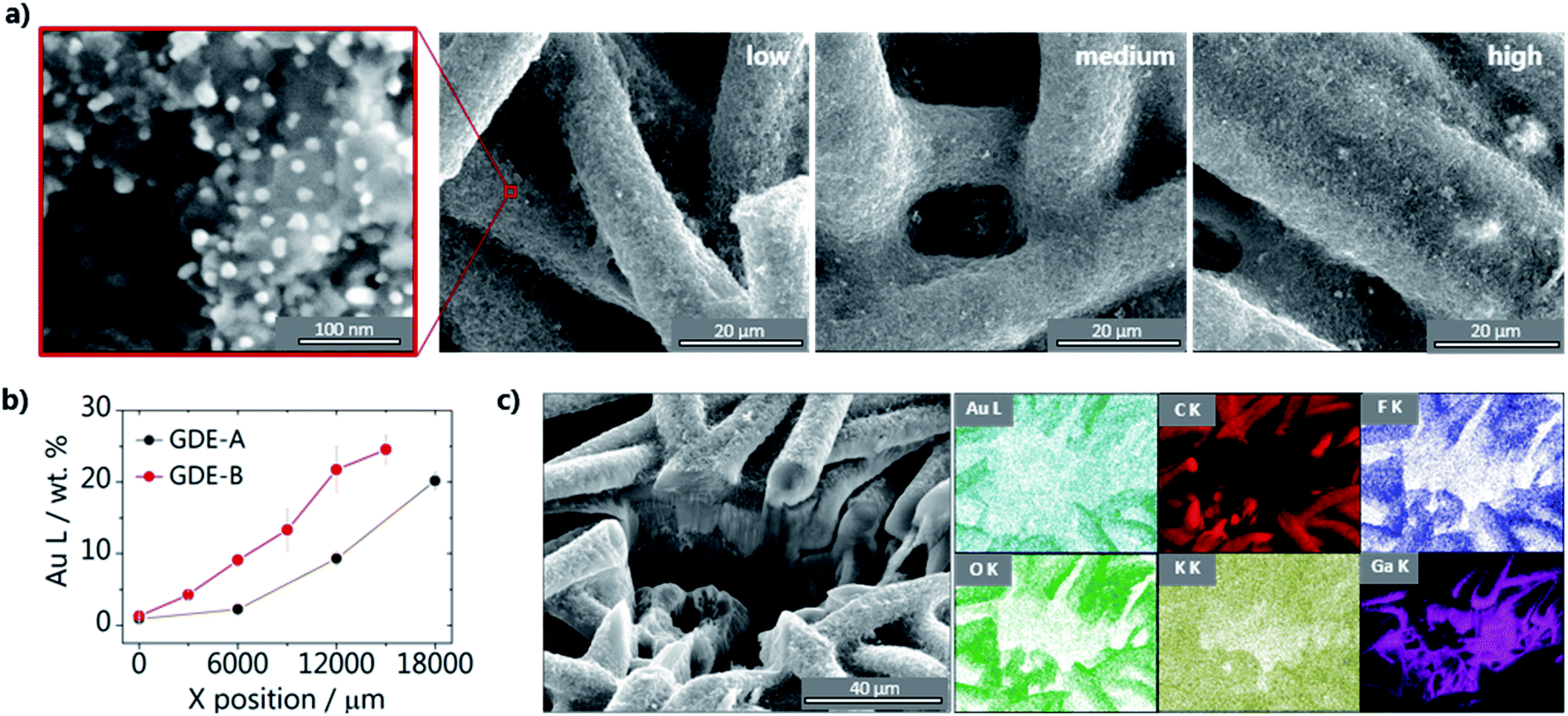 | ||
| Fig. 1 Characterization of the gas diffusion electrodes. (a) SEM micrographs taken in the low, medium and high loading regions of a Au/C catalyst gradient sprayed on the gas diffusion layer. The zoomed-in image (red box) shows the shape and distribution of the 20 nm particles on the GDE. (b) Gold weight percentage measured with EDX along the loading gradient showing a shallow (GDE-A) and steep (GDE-B) gradient. Each data point is an average of three measurements taken along the Y axis at a given X-position, and error bars are the respective standard deviation. (c) SEM micrograph of the cross-section of GDE-B exposed after milling with a focused ion beam, together with the EDX elemental maps recorded in the same area. | ||
Different volumes of the catalyst ink were sprayed along 2 cm of carbon/PTFE GDE surfaces (Fig. 2a), leading to GDE-A, exhibiting a shallow Au/C gradient, and GDE-B, having a steep increase in the amount of Au nanoparticles along the length of the sample. Having GDEs with different loading gradients not only aids in validating our methodology, but also provides valuable information on the interplay between loading and CO2 pressure (see below) GDE-A was used primarily to investigate the effect of the catalyst loading, while GDE-B was used to look at the effect of the CO2 back pressure on the local activity for CO. It is important to point out that in order to assure the feasibility of the experiment, the substrate used for this work does not contain a microporous layer, so the catalyst ink was applied directly onto the gas diffusion layer. Nevertheless, this does not compromise the evaluation of the effect of catalyst loading on the activity, which is the main goal of this work. Fig. 1a shows SEM images, representative of the different loading regions of the resulting GDEs. At the low loading area, the carbon fibers are not entirely covered by the Au/C nanoparticles. As moving to regions of higher loading, the coverage increases as the shape of the fibers becomes less evident and the gaps between the fibers are filled with the catalyst ink. The volume of catalyst ink dispensed at each spray increment along the length of GDEs A and B indicates the steepness of the two different catalyst gradients (see Fig. S3; ESI†). In addition, we characterized the different loading regions using energy dispersive X-rays (EDX) mapping for comparing the gradient of Au along the length of the GDEs. The percentage of Au found along GDE-A and GDE-B is displayed in Fig. 1b, showing that, as expected, for GDE-B, a steeper increase along the gradient is achieved compared with GDE-A. The values are an average of three measurements around a given position. It is important to point out that due to the large areas sampled, this is only a semi-quantitative analysis, used to probe the steepness of the catalyst gradients. The EDX results are exemplarily shown in Fig. S4† and S5 in the ESI,† together with SEM micrographs of GDE-A and GDE-B at the corresponding positions. Due to the complex morphology of the GDEs, we used focused ion beam (FIB) milling in combination with EDX to evaluate the composition of the GDEs through a cross-sectional cut perpendicular to the surface. Results for GDE-B are shown in Fig. 1c, and the SEM image suggests that the GDE exhibits dense areas together with a few long pore-type channels connected throughout the fibers. EDX elemental analysis shows the presence of Au, C, F, O, K, and Ga (which originates from the ion source of the FIB). The majority of the Au/C nanoparticles are located on top of the fibers. As EDX characterization was performed after CO2 electrolysis in KHCO3, K is found throughout the whole imaged area. As recently shown by Cofell et al.,33 this is due to KHCO3 deposition due to concentration gradients and increased local alkalinity developed during electrolysis.
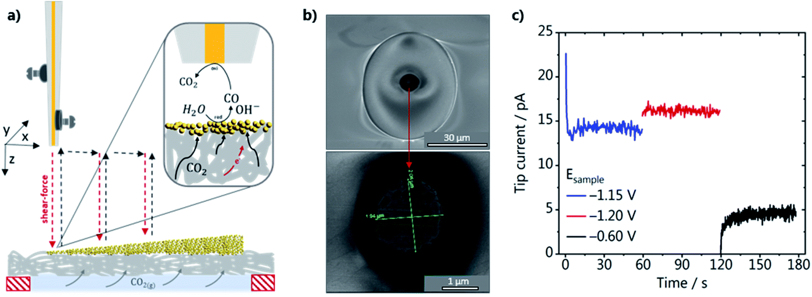 | ||
| Fig. 2 (a) Schematic representation of the SECM experimental setup, with piezo elements mounted at the Au-nanoelectrode tip, approaching a catalyst loading gradient in hopping mode. The SECM is operated in SG-TC mode, as shown in the inset; (b) SEM micrographs of the gold nanoelectrode; (c) tip current recorded at a constant potential of 0.19 V vs. Ag/AgCl/3 M KCl, upon applying different potentials to the GDE in 1 M CO2 saturated KHCO3. | ||
SECM with shear–force positioning
The activity of the GDEs was evaluated in the SG-TC mode of SECM, as schematically shown in Fig. 2a. The GDEs were mounted on a specifically designed cell (see Fig. S2 in the ESI†) so that the whole catalyst gradient was in contact with the electrolyte, while CO2 was constantly fed in a flow-by configuration through the gas channel at the backside of the GDE. A Au-nanoelectrode was used to detect the local amount of CO produced while CO2RR reoccurred at the GDE. The Au wire was platinized before it was inserted into the laser puller to improve the adhesion between the Au wire and the insulating quartz capillary to fabricate a well-sealed Au-nanoelectrode. SEM micrographs of a Au-nanoelectrode with a tip radius of 1.0 ± 0.02 μm are shown in Fig. 2b. During the SECM measurements, the tip was brought as close as about 100 nm to the GDE surface at every XY position by performing a shear–force based approach.34 A frequency spectrum and an example of an approach curve can be seen in Fig. S6 (ESI).† A blank voltammogram of the Au-nanoelectrode was recorded in the shear–force interaction region before each experiment (Fig. S7a†), showing that at the chosen experimental conditions in CO2 saturated 1 M KHCO3 only voltammetric features characteristic of the Au oxide formation, reduction and double layer charging are present.35 To assure that applying different potentials to the GDE does not affect the nanoelectrode current and that the catalyst-free GDE is inert, we have also consecutively recorded voltammograms of the Au-nanoelectrode in the shear–force interaction distance while stepping the potential at the catalyst-free GDE from −0.6 to −1.4 V vs. Ag/AgCl/3 M KCl (Fig. S7b†). We did not observe any CO formation at the catalyst-free GDE, evidenced by the stable double layer charging current in the potential range between −0.25 and 0.6 V vs. Ag/AgCl/3 M KCl. To demonstrate that the Au nanoelectrode responds to CO, a calibration gas containing 1 vol% CO was fed through the back of the GDE for 10 s while a potential of −0.6 V vs. Ag/AgCl/3 M KCl was applied to the GDE (Fig. S6a†). Two characteristic anodic current plateaus become visible due to diffusion-limited CO oxidation to CO2. These two plateaus appear only in a specific alkaline pH range, as shown previously, confirming that they are due to CO oxidation limited by the diffusion of two different species.26,36 At more positive potentials, more specifically at 1.2 V vs. Ag/AgCl/3 M KCl, the anodic current is due to oxygen evolution. The two voltammetric cycles recorded before the gas mixture was introduced show the difference in magnitude between the double-layer charging and the faradaic current due to CO oxidation. In the next step, we evaluated the voltammetric response of the Au nanoelectrode, which was positioned in the shear–force interaction distance above the GDE, at potentials of −0.6 and −1.2 V vs. Ag/AgCl/3 M KCl applied to GDE-A (shallow catalyst gradient) in 1 M KHCO3 under a CO2 back pressure of 2 mbar. The voltammograms for the two GDE potentials are shown in Fig. S8b in the ESI.† At −0.6 V vs. Ag/AgCl/3 M KCl applied at the GDE only current due to double layer charging is observed at the Au-nanoelectrode, whereas at −1.2 V vs. Ag/AgCl/3 M KCl a diffusion-limited plateau arises. Although the voltammetric features are very similar to the ones observed when using the calibration gas (Fig. S8a†), a distinct shift of the CO oxidation current plateau to more negative potentials is observed due to the concurrent formation of OH− and an increase in the local alkalinity. The Au-nanoelectrode current was recorded at a fixed potential of 0.190 V vs. Ag/AgCl/3 M KCl during the SECM scans to account for these possible shifts, a potential which is located in the middle of the diffusion-limited CO oxidation plateau current under operando conditions. An example of the current that is recorded at the Au-nanoelectrode in the shear–force interaction distance during a SECM scan is shown in Fig. 2c. Stable and constant diffusion-limited currents increasing from GDE potentials of −1.15 to −1.2 V vs. Ag/AgCl/3 M KCl due to the concomitantly increasing amount of CO produced at the GDE are observed. In contrast, when the GDE potential is −0.6 V, the current drops and is only due to the charging of the Au-nanoelectrode double layer.Effect of the catalyst loading
We have evaluated the amount of CO produced along the catalyst gradients of GDE-A and GDE-B using the diffusion-limited CO oxidation current recorded at the Au-nanoelectrode. All SECM experiments were performed in the hopping mode, where at each XY-position, a shear–force approach curve was performed. The Au-nanoelectrode current at different GDE potentials was recorded in the shear–force interaction distance (∼100 nm above the GDE surface), and then the Au-nanoelectrode was retracted and moved to a new XY-coordinate (Fig. 2a). The average diffusion-limited CO oxidation current recorded at the Au-nanoelectrode during 60 s at every X-position and constant Y-position along the GDE is shown for different GDE potentials. Results for GDE-A, at a CO2 back pressure of 2 mbar, are shown in Fig. 3a. We observe that the increase in catalyst loading along the X-direction leads to a nearly linear increase in the amount of CO produced, as the tip current rises from 4 pA (at X = 0 μm) to almost 6 pA (at X = 17![[thin space (1/6-em)]](https://www.rsc.org/images/entities/char_2009.gif) 000 μm). However, surprisingly, most of the activity comes from localized hot spots, which are present both in the low and high loading regions of GDE-A. CO hotspots and CO2 pockets (marked with a red shade in the SECM array scan; Fig. 3) were detected at certain X-positions where not only relatively higher CO oxidation currents were measured at the Au-nanoelectrode, but also constant bubble formation was disturbing the Au-nanoelectrode signal. Bubbles were identified due to the signature of the noise they cause in the Au-nanoelectrode current response (see Fig. S9 in the ESI†). The CO hot spots and CO2 pockets were determined as follows: CO hot spots (marked with a yellow shade in the SECM array scan; Fig. 3) were identified at positions where the noise in the Au-nanoelectrode current was only detected upon applying potentials of −1.20 or −1.15 V vs. Ag/AgCl/3 M KCl to the GDE, therefore being associated to CO formation due to CO2 reduction. In contrast, CO2 pockets were identified at positions where also at a potential of −0.6 V vs. Ag/AgCl/3 M KCl (when there is no CO produced at the GDE), the Au-nanoelectrode current was showing the characteristic noise due to bubbles. This means that at these XY positions, CO2 constantly percolates through the pore channels and is released into the electrolyte. Due to the high concentration of CO2 in these spots, every CO2 pocket is also consequently a CO hot spot, while not every CO hot spot was a CO2 pocket. It is important to point out that the bubble-associated noise was not considered for calculating the average diffusion-limited currents as it is not representative of the CO concentration (at −1.20 or −1.15 V) or the double layer charging current (at −0.6 V). Therefore, pockets and hotspots were just marked with the red and yellow shades. Fig. 3a zooms in the low current range, and a plot displaying the complete current range is shown in Fig. S10 in the ESI.† The current at the hotspot locations is up to 5–6 times higher than the maximum current obtained at the other measurement areas of the catalyst gradient. This suggests that at the relatively low catalyst loading along the gradient, the formation of the three-phase boundary within the GDE is more critical to assure high activity than the amount of catalyst on the GDE surface. Additionally, it is important to point out that the pore network and transport properties of the gas diffusion layer may play an important role on the formation of these hot spots. For example, CO can accumulate in the pores near highly active areas of the GDE. These gas-filled pores find the optimal pore system for breaking through and therefore the surface of the GDE where the gas-filled pore network opens to the bulk electrolyte is detected as a hot spot. An example of such a pore system can actually be seen in the FIB cross section depicted in Fig. 1c. Despite the complexity of these processes, our measurements show how inhomogeneous the activity is along the gradient and that a higher catalyst loading alone, does not assure high activity.
000 μm). However, surprisingly, most of the activity comes from localized hot spots, which are present both in the low and high loading regions of GDE-A. CO hotspots and CO2 pockets (marked with a red shade in the SECM array scan; Fig. 3) were detected at certain X-positions where not only relatively higher CO oxidation currents were measured at the Au-nanoelectrode, but also constant bubble formation was disturbing the Au-nanoelectrode signal. Bubbles were identified due to the signature of the noise they cause in the Au-nanoelectrode current response (see Fig. S9 in the ESI†). The CO hot spots and CO2 pockets were determined as follows: CO hot spots (marked with a yellow shade in the SECM array scan; Fig. 3) were identified at positions where the noise in the Au-nanoelectrode current was only detected upon applying potentials of −1.20 or −1.15 V vs. Ag/AgCl/3 M KCl to the GDE, therefore being associated to CO formation due to CO2 reduction. In contrast, CO2 pockets were identified at positions where also at a potential of −0.6 V vs. Ag/AgCl/3 M KCl (when there is no CO produced at the GDE), the Au-nanoelectrode current was showing the characteristic noise due to bubbles. This means that at these XY positions, CO2 constantly percolates through the pore channels and is released into the electrolyte. Due to the high concentration of CO2 in these spots, every CO2 pocket is also consequently a CO hot spot, while not every CO hot spot was a CO2 pocket. It is important to point out that the bubble-associated noise was not considered for calculating the average diffusion-limited currents as it is not representative of the CO concentration (at −1.20 or −1.15 V) or the double layer charging current (at −0.6 V). Therefore, pockets and hotspots were just marked with the red and yellow shades. Fig. 3a zooms in the low current range, and a plot displaying the complete current range is shown in Fig. S10 in the ESI.† The current at the hotspot locations is up to 5–6 times higher than the maximum current obtained at the other measurement areas of the catalyst gradient. This suggests that at the relatively low catalyst loading along the gradient, the formation of the three-phase boundary within the GDE is more critical to assure high activity than the amount of catalyst on the GDE surface. Additionally, it is important to point out that the pore network and transport properties of the gas diffusion layer may play an important role on the formation of these hot spots. For example, CO can accumulate in the pores near highly active areas of the GDE. These gas-filled pores find the optimal pore system for breaking through and therefore the surface of the GDE where the gas-filled pore network opens to the bulk electrolyte is detected as a hot spot. An example of such a pore system can actually be seen in the FIB cross section depicted in Fig. 1c. Despite the complexity of these processes, our measurements show how inhomogeneous the activity is along the gradient and that a higher catalyst loading alone, does not assure high activity.
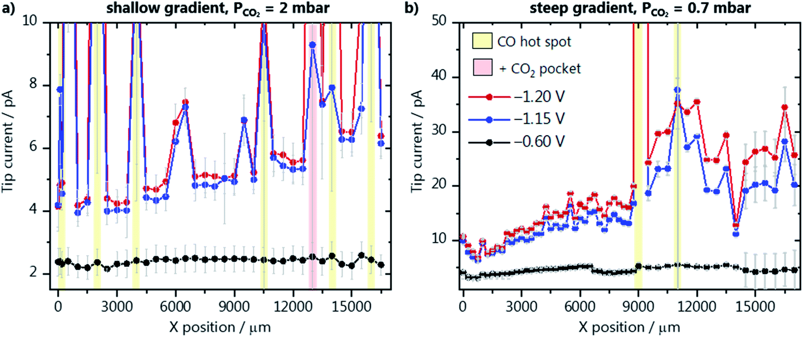 | ||
| Fig. 3 SECM array scans along (a) the catalyst gradient of GDE-A at a CO2 back-pressure of 2 mbar, and (b) the steep gradient of GDE-B at a CO2 pressure of 0.7 mbar. The potentials applied to the GDEs were −1.2 V (red), −1.15 V (blue) and −0.6 V (black) vs. Ag/AgCl/3 M KCl in 1 M KHCO3 as electrolyte. CO hot spots and CO2 pockets are marked with a yellow and red shade, respectively. | ||
The activity along GDE-B with a steeper catalyst gradient was also evaluated, however, at a lower CO2 back pressure of 0.7 mbar (Fig. 3b). In general, higher activity is observed in comparison to GDE-A, despite the lower CO2 pressure. Up to X = 11000 μm, a steeper increase in the amount of formed CO is seen, which is in good agreement with the EDX characterization (Fig. 1b). In contrast to the results obtained from GDE-A, the activity starts to decrease for GDE-B at X > 11000 μm. Due to the lower CO2 availability and the higher density and thickness of the catalyst layer, it seems that at higher loading, a part of the Au/C nanoparticles is less accessible to the CO2. At lower backpressure, no CO2 pockets and nearly no CO hot spots along GDE-B are detected. We have also investigated the relationship between activity and GDE topography to better understand the effect of the CO2 gradient through the gas diffusion layer. A height profile was derived from the absolute Z-position of the shear–force interaction distance of the closest approach of the Au-nanoelectrode above the GDE surface. This topography profile is plotted together with the Au-nanoelectrode current from Fig. 3b at −1.2 V vs. Ag/AgCl/3 M KCl (Fig. S11 in the ESI†). Interestingly, locations where more CO is detected (indicated by red arrows) coincide with lower absolute Z-positions of the Au-nanoelectrode. This suggests a CO2 concentration gradient from the back towards the surface of the GDE, and hence at these lower Z-positions, e.g. above a pore, the local concentration of CO2 is likely higher, yielding more CO. The same analysis cannot be done for the measurement from Fig. 3a (GDE-A), as the large amount of bubbles leads to an uncertainty in the positioning of the Au-nanoelectrode over CO2 pockets and CO hotspots.
High resolution activity map
To better understand how localized the hot spots are, and how much the activity can vary within a small area of the GDE, we have recorded activity maps on a 30 × 30 μm area of GDE-B. The origin of the map (X,Y = 0,0) corresponds to position X = 10000 μm (in Fig. 3b) within the high activity region along the catalyst concentration gradient. For constructing the activity maps, at each XY position a Z-approach was carried out and the CO oxidation current was recorded at the tip while four different potentials were applied to the GDE (−1.15, −1.20, −1,25 and −0.60 V vs. Ag/AgCl/3 M KCl). The current determined at each position was normalized to the double-layer charging current recorded at −0.6 V, to account for slight changes of the tip response, which can occur during these long-term measurements (∼14 h). The activity maps at different GDE potentials are shown in Fig. 4, and the data processing in Fig. S12 in the ESI.† We observe a similar activity trend as for the array scans in Fig. 3a and b, where more CO is formed at more negative potentials. Interestingly, large differences in activity are observed, demonstrating the inhomogeneity of the lateral response over the GDEs. For example, at position (X,Y = 0,0), the activity is seven times higher than at the center of the mapped area (X,Y = 15,15). As the catalyst gradient was formed over a much wider length of the GDE (1.7 cm) than the one visualized in the array scan in Fig. 4 (30 μm), we hypothesize that the detected differences are not due to a difference in the catalyst loading. These differences highlight that apart from a high catalyst loading, it is imperative to supply enough CO2 and to provide a homogeneous distribution of pores of the GDE accessible for CO2, in order to form a three-phase reaction boundary. The used experimental SECM-based strategy allows to spatially resolve inhomogeneous CO2RR activity, which is a direct result of inhomogeneous three-phase boundary properties within the GDE pore system. Thus, different CO fluxes detected at the Au nanoelectrode are not only a function of catalyst quantity at a given location, but are additionally related to the gas transport of CO2 through channels below the actual accessible GDE surface as well as the local reaction rate and the concomitant local change in the pH value.
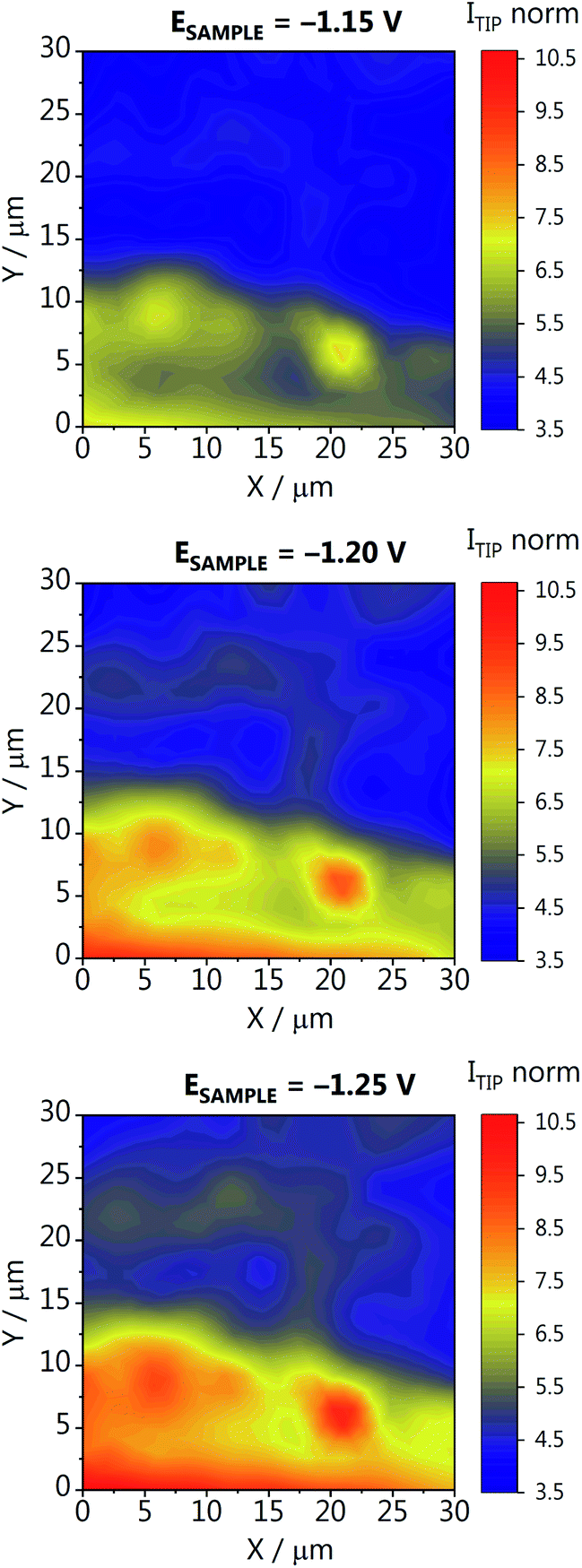 | ||
| Fig. 4 Activity map recorded for GDE-B at a CO2 back-pressure of 0.7 mbar. The different GDE potentials are reported versus Ag/AgCl/3 M KCl in 1 M KHCO3. The tip current (ITIP norm) is normalized to the double-layer charging current recorded at −0.6 V. | ||
We have marked the region where the activity maps were measured to analyze the morphology–activity relationship of the GDE. After the experiments, GDE-B was marked with a 1.2 mm tip, at two known and safe distances from the area that was mapped (Fig. S13 in the ESI†). SEM images of the marked GDE area were obtained, and although we cannot assure the location of the specific area of the SECM activity map with a sufficiently small confidence interval, a quite high number of larger pores can be seen in this region. From Fig. S11 (ESI)† we are confident that the area is very similar to the area selected as shown in Fig. S13b and c.† Above and in the pores, the concentration of CO2, and consequently the formed CO, is significantly higher than above the topmost fibers of the GDE. These deeper pores and differences in the pore network are most likely responsible for the significant activity differences shown in Fig. 4. Even though catalyst particles may not be present throughout the whole pore length, they still serve as CO2 channels and assure high CO2 availability to the particles located closer to the surface.
Effect of the CO2 pressure
As most results so far point out the importance of CO2 reaching the wetted catalyst layer, we have also performed an array scan along GDE-B, but now at a CO2 back-pressure of 4.2 mbar (Fig. 5). This is the highest possible CO2 pressure at which we could perform SECM measurements without gas bubbles disturbing the electrolyte. Surprisingly, compared to Fig. 3b, we see that upon increasing the CO2 pressure, the activity in the low loading region (0 < X < 7000) increases by an order of magnitude (Fig. 5). However, here the effect of the catalyst gradient is much less pronounced. Due to the higher back-pressure, more hot spots and CO2 pockets are formed along the catalyst loading gradient. In contrast to the low loading region, above X = 7500 μm (compare Fig. 3b), a large increase in the Au nanoelectrode current is seen reaching a maximum at a higher catalyst loading than at a CO2 back-pressure of 0.7 mbar. This suggests that a large portion of the catalyst layer is not utilized at lower back-pressure because it is not reached by the reactant. Once the CO2 pressure is increased, the maximum activity is shifted to a higher catalyst loading area. If the loading is too high, the surface will be blocked and it will be more difficult for CO2 to reach the active sites at the catalyst surface.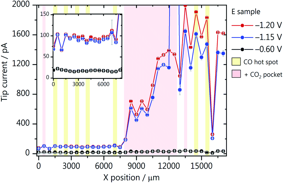 | ||
| Fig. 5 SECM array scans through the catalyst gradient of GDE-B at a CO2 back-pressure of 4.2 mbar. The applied GDE potentials were −1.2 V (red), −1.15 V (blue) and −0.6 V (black), reported versus Ag/AgCl/3 M KCl and measurements were performed in 1 M KHCO3. CO hot spots and CO2 pockets are marked with a yellow and red shade, respectively. | ||
Final remarks
These results have implications for the design and optimization of GDE-based CO2 electrolysis systems. We see that overall, higher catalyst loadings lead to higher activity for CO, provided enough CO2 is supplied. However, we can now also better understand why results in literature show opposing dependencies regarding the relation between local CO2R activity and catalyst loading in GDEs. The optimal loading to achieve the highest activity is strongly dependent on the CO2 back-pressure and the permeability of the gas diffusion substrate (Fig. 3b and 5). For example, we previously performed experiments with a large excess of CO2, and the GDE with lower catalyst loading exhibited a higher faradaic efficiency for CO.14 On the other hand, Duarte et al.6 observed an increase in CO partial current density with increasing loading but with no effect on the faradaic efficiency. This also points out to the fact that different gas diffusion layers highly differ in terms of how the pore channels are distributed and how permeable and hydrophobic the layer is. All these parameters will play a role and should be tested for and considered when establishing optimum operation conditions for GDEs. Despite the complexity of GDE-based CO2 electrolyser systems, we have now a tool at hand to go one step further in finding the optimal operation parameters based on the local information which can be attained using the experiments we show here. Even though we could already obtain valuable insights into the effect of catalyst loading on the activity of GDEs, a more systematic study would allow to establish more quantitative system design rules. Additionally, we propose that spray-coating, the currently most used production process for GDEs, may not be ideal in the sense that most of the catalyst particles are located only at the topmost layer of the GDE, where the CO2 concentration is lowest in a flow-through or flow-by configuration. This suggests that the catalyst particles should be dispersed within the GDE matrix and homogeneously distributed along the electrode cross-section, while still, of course, allowing for electrolyte to percolate. In that way, most of the catalyst will be utilized, and the CO2 back-pressure can be moderate.Conclusions
We have assessed the effect of catalyst loading and CO2 pressure on the activity of Au GDEs. We used shear–force based Au-nanoelectrode positioning, and the SG-TC SECM mode in combination with catalyst loading gradients on the GDE. CO2 reduction to CO was carried out and the formed CO was detected in situ using the Au nanoelectrode. Our results show that higher catalyst loadings lead to higher activity for CO, provided that enough CO2 is supplied. We confirm experimentally, that an optimum balance between the available amount of catalyst and the supplied CO2 is necessary to achieve high activity for CO2 reduction. Evidently, employing a large amount of catalyst without providing enough CO2 does not sufficiently utilize the catalyst. The proposed methodology opens up opportunities for probing the activity of GDEs locally in a more controlled manner than using conventional product detection techniques. On top of that, the shear–force positioning used here, allows to directly correlate the activity data with the electrode topography. With that, the influence of other variables on the activity of GDEs can be investigated, such as gas diffusion layer composition and GDE porosity.Data availability
The data that support the findings of this study are available upon reasonable request.Author contributions
M. C. O. M. and S. D. contributed equally and carried out all measurements together. M. C. O. M., S. D., M. T. M. K. and W. S. designed the experiments and M. C. O. M. wrote the manuscript with input from all authors. T. B. performed the spraying of gas diffusion electrodes and T. Q. the SEM/EDX characterization. D. P. contributed to the synthesis of Au/C nanoparticles.Conflicts of interest
There are no conflicts to declare.Acknowledgements
This project has received funding from the European Research Council (ERC) under the European Union's Horizon 2020 research and innovation programme (grant agreement CasCat [833408]) as well as from the Deutsche Forschungsgemeinschaft (DFG, German Research Foundation) in the framework of the research unit FOR 2397e2 (276655237). M. C. O. M. and M. T. M. K. acknowledge the support of the European Commission under contract 722614 (Innovative Training Network Elcorel).Notes and references
- R. Kortlever, J. Shen, K. J. P. Schouten, F. Calle-Vallejo and M. T. M. Koper, J. Phys. Chem. Lett., 2015, 6, 4073–4082 CrossRef CAS PubMed.
- Y. Y. Birdja, E. Pérez-Gallent, M. C. Figueiredo, A. J. Göttle, F. Calle-Vallejo and M. T. M. Koper, Nat. Energy, 2019, 4, 732–745 CrossRef CAS.
- B. A. Zhang, T. Ozel, J. S. Elias, C. Costentin and D. G. Nocera, ACS Cent. Sci., 2019, 5, 1097–1105 CrossRef CAS PubMed.
- A. Goyal, G. Marcandalli, V. A. Mints and M. T. M. Koper, J. Am. Chem. Soc., 2020, 142, 4154–4161 CrossRef CAS PubMed.
- J.-B. Vennekötter, T. Scheuermann, R. Sengpiel and M. Wessling, J. CO2 Util., 2019, 32, 202–213 CrossRef.
- M. Duarte, B. De Mot, J. Hereijgers and T. Breugelmans, ChemElectroChem, 2019, 6, 5596–5602 CrossRef CAS.
- S. S. Bhargava, F. Proietto, D. Azmoodeh, E. R. Cofell, D. A. Henckel, S. Verma, C. J. Brooks, A. A. Gewirth and P. J. A. Kenis, ChemElectroChem, 2020, 7, 2001–2011 CrossRef CAS.
- P. Jeanty, C. Scherer, E. Magori, K. Wiesner-Fleischer, O. Hinrichsen and M. Fleischer, J. CO2 Util., 2018, 24, 454–462 CrossRef CAS.
- T. Burdyny and W. A. Smith, Energy Environ. Sci., 2019, 12, 1442–1453 RSC.
- M. Dunwell, W. Luc, Y. Yan, F. Jiao and B. Xu, ACS Catal., 2018, 8, 8121–8129 CrossRef CAS.
- K. J. Puring, D. Siegmund, J. Timm, F. Möllenbruck, S. Schemme, R. Marschall and U. P. Apfel, Adv. Sustainable Syst., 2021, 5, 1–13 Search PubMed.
- J. B. Vennekoetter, R. Sengpiel and M. Wessling, Chem. Eng. J., 2019, 364, 89–101 CrossRef CAS.
- L. Weng, A. T. Bell and A. Z. Weber, Phys. Chem. Chem. Phys., 2018, 20, 16973–16984 RSC.
- M. C. O. Monteiro, M. F. Philips, K. J. P. Schouten and M. T. M. Koper, Nat. Commun., 2021, 12, 4943 CrossRef CAS PubMed.
- B. De Mot, J. Hereijgers, M. Duarte and T. Breugelmans, Chem. Eng. J., 2019, 378, 122224 CrossRef CAS.
- B. Endrődi, G. Bencsik, F. Darvas, R. Jones, K. Rajeshwar and C. Janáky, Prog. Energy Combust. Sci., 2017, 62, 133–154 CrossRef.
- X. Lu, D. Y. C. Leung, H. Wang and J. Xuan, Appl. Energy, 2017, 194, 549–559 CrossRef CAS.
- M. E. Leonard, L. E. Clarke, A. Forner-Cuenca, S. M. Brown and F. R. Brushett, ChemSusChem, 2020, 13, 400–411 CrossRef CAS PubMed.
- T. Kai, M. Zhou, Z. Duan, G. A. Henkelman and A. J. Bard, J. Am. Chem. Soc., 2017, 139, 18552–18557 CrossRef CAS PubMed.
- R. G. Mariano, K. McKelvey, H. S. White and M. W. Kanan, Science, 2017, 358, 1187–1192 CrossRef CAS PubMed.
- R. G. Mariano, M. Kang, O. J. Wahab, I. J. McPherson, J. A. Rabinowitz, P. R. Unwin and M. W. Kanan, Nat. Mater., 2021, 20, 1000–1006 CrossRef CAS PubMed.
- F. D. Mayer, P. Hosseini-Benhangi, C. M. Sánchez-Sánchez, E. Asselin and E. L. Gyenge, Commun. Chem., 2020, 3, 1–9 CrossRef.
- A. Botz, J. Clausmeyer, D. Öhl, T. Tarnev, D. Franzen, T. Turek and W. Schuhmann, Angew. Chem., Int. Ed., 2018, 57, 12285–12289 CrossRef CAS PubMed.
- S. Dieckhöfer, D. Öhl, J. R. C. Junqueira, T. Quast, T. Turek and W. Schuhmann, Chem.–Eur. J., 2021, 27, 5906–5912 CrossRef PubMed.
- M. C. O. Monteiro, F. Dattila, B. Hagedoorn, R. García-Muelas, N. López and M. T. M. Koper, Nat. Catal., 2021, 4, 654–662 CrossRef CAS.
- M. C. O. Monteiro, L. Jacobse and M. T. M. Koper, J. Phys. Chem. Lett., 2020, 11, 9708–9713 CrossRef CAS PubMed.
- J. Kimling, M. Maier, B. Okenve, V. Kotaidis, H. Ballot and A. Plech, J. Phys. Chem. B, 2006, 110, 15700–15707 CrossRef CAS PubMed.
- J. R. C. Junqueira, T. Bobrowski, O. A. Krysiak, R. Gutkowski and W. Schuhmann, ChemCatChem, 2019, 11, 6417–6424 CrossRef CAS.
- T. Bobrowski, F. Conzuelo, A. Ruff, V. Hartmann, A. Frank, T. Erichsen, M. M. Nowaczyk and W. Schuhmann, ChemPlusChem, 2020, 85, 1396–1400 CrossRef CAS PubMed.
- M. Nebel, K. Eckhard, T. Erichsen, A. Schulte and W. Schuhmann, Anal. Chem., 2010, 82, 7842–7848 CrossRef CAS PubMed.
- A. Wuttig and Y. Surendranath, ACS Catal., 2015, 5, 4479–4484 CrossRef CAS.
- K. Elumeeva, J. Masa, D. Medina, E. Ventosa, S. Seisel, Y. U. Kayran, A. Genç, T. Bobrowski, P. Weide, J. Arbiol, M. Muhler and W. Schuhmann, J. Mater. Chem. A, 2017, 5, 21122–21129 RSC.
- E. R. Cofell, U. O. Nwabara, S. S. Bhargava, D. E. Henckel and P. J. A. Kenis, ACS Appl. Mater. Interfaces, 2021, 13, 15132–15142 CrossRef CAS PubMed.
- A. Hengstenberg, C. Kranz and W. Schuhmann, Chem.–Eur. J., 2000, 6, 1547–1554 CrossRef CAS.
- M. C. O. Monteiro and M. T. M. Koper, Electrochim. Acta, 2019, 325, 134915 CrossRef CAS.
- G. Marcandalli, M. Villalba and M. T. M. Koper, Langmuir, 2021, 37, 5707–5716 CrossRef CAS PubMed.
Footnotes |
| † Electronic supplementary information (ESI) available: Pictures of the experimental setup, additional SEM and EDX characterization of the gas diffusion electrodes, approach curve, gold nanoelectrode voltammetry, array scans and topography data, data treatment of the activity maps. See DOI: 10.1039/d1sc05519d |
| ‡ These authors contributed equally. |
| This journal is © The Royal Society of Chemistry 2021 |