Facile and efficient recovery of lithium from spent LiFePO4 batteries via air oxidation–water leaching at room temperature†
Hao
Jin
ab,
Jialiang
Zhang
 *abc,
Duoduo
Wang
ab,
Qiankun
Jing
ab,
Yongqiang
Chen
*abc and
Chengyan
Wang
 abc
abc
aState Key Laboratory of Advanced Metallurgy, University of Science and Technology Beijing, No. 30 Xueyuan Road, Haidian District, Beijing 100083, China. E-mail: jialiangzhang@ustb.edu.cn; chyq0707@sina.com; Fax: +861062333170; Tel: +861062332271
bSchool of Metallurgical and Ecological Engineering, University of Science and Technology Beijing, No. 30 Xueyuan Road, Haidian District, Beijing 100083, China
cBeijing Key Laboratory of Green Recycling and Extraction of Metals, No. 30 Xueyuan Road, Haidian District, Beijing 100083, China
First published on 25th October 2021
Abstract
The economical recycling of the spent LiFePO4 batteries in industry is challenging due to its low lithium recovery rate, and high reagent and wastewater treatment costs. Here, air oxidation–water leaching was directly employed to selectively recover lithium from the spent LFP material, in which the high leaching efficiency of lithium and the good separation effect of lithium and iron were achieved simultaneously. The thermodynamic analysis indicates that lithium can be selectively extracted under a weak acid and oxidizing atmosphere. XRD, AC-TEM, TOF-SIMS, etc. were employed to investigate the leaching mechanism, and it reveals that the oxidation of Fe and the de-intercalation of Li take place simultaneously and the ratio of the FePO4 phase to LiFePO4 phase gradually increases in the lithium leaching course, and the olivine structure remains essentially unchanged. 99.3% of Li is leached into solution, while only 0.02% Fe and P are dissolved. The kinetic study result suggests that selective leaching of Li is diffusion controlled. Eventually, a new LFP cathode material was prepared with Li2CO3 (obtained from the leachate) and the FePO4 residue, exhibiting sound electrochemical performance. The proposed method enjoys the benefits of a high lithium recovery rate, low waste generation and high economic profit, which paves a promising way to recycle the spent LFP material.
1 Introduction
The olivine lithium iron phosphate (LFP) cathode exhibits the merits of low-cost, safety, excellent thermal stability and superior cycling performance compared with other cathode materials of lithium-ion batteries.1 In particular in China, the advantages of LFP batteries have been more outstanding recently as the state subsidies for the new electric vehicles (EVs) decrease and the price of cobalt increases. Naturally, LFP (as a kind of cobalt-free material) batteries will be preferred by more and more automobile manufacturers. A huge number of end-of-life batteries will emerge due to the limited lifespan of LFP batteries (8–10 years).2,3 The toxic electrolytes, binder, and other organic chemicals will result in serious environmental pollution if the spent batteries were not properly treated.4 Besides, China is the largest consumer of lithium, while only 7% of lithium is produced by itself and the rest is imported from overseas.5 The spent LFP batteries were urban mineral resources of high added value, containing about 1%–2% lithium by weight.6 Thus, the recycling of the spent LFP batteries is significant to reduce the dependence on lithium imports and minimize the environmental pollution induced by the used batteries, which conforms to the concept of green, low carbon and sustainable development.Two strategies for recycling LFP batteries have been widely developed: the direct regeneration of cathode materials and the hydrometallurgical route to recycle the valuable elements (or further re-synthesize LFP cathode materials). Generally, the failure of LFP batteries results from lithium loss and the olivine crystal structure remains unchanged. The capacity of LFP batteries could be healed with additional lithium supplements via high temperature,7–10 hydrothermal11,12 or electrochemical processes.13 While the direct regeneration technology is only suitable for cathode materials with low impurities and high consistency. The hydrometallurgical method has more applicability for the raw cathode material. In previous works, organic acid (e.g., methyl sulfonic acid,14 oxalic acid15) and mineral acid (e.g., H2SO4![[thin space (1/6-em)]](https://www.rsc.org/images/entities/char_2009.gif) 16 HCl,17,18 H3PO4
16 HCl,17,18 H3PO4![[thin space (1/6-em)]](https://www.rsc.org/images/entities/char_2009.gif) 19,20) have been employed as leaching agents. In the traditional leaching–precipitation process, Li, Fe and P were first dissolved in the leaching solution and the precipitation of FePO4 was followed by adjusting the pH with NaOH. Subsequently, the product of Li2CO3 was prepared from the leachate with saturated Na2CO3 after a further increase in pH to 10–11. However, the first formed FePO4 particles were too small, leading to a large number of lithium ions being trapped, which consequently decreases the recovery rate of lithium. In addition, excessive acid and alkali were used in this process, resulting in a large amount of salty wastewater. The poor economic profit resulted from the low lithium recovery rate and the high cost of wastewater treatment is the bottleneck of recycling the spent LFP batteries. This results in the present situation that the industrial recycling of LFP batteries has not been realized, limiting the sustainable development of the lithium-ion battery industry.
19,20) have been employed as leaching agents. In the traditional leaching–precipitation process, Li, Fe and P were first dissolved in the leaching solution and the precipitation of FePO4 was followed by adjusting the pH with NaOH. Subsequently, the product of Li2CO3 was prepared from the leachate with saturated Na2CO3 after a further increase in pH to 10–11. However, the first formed FePO4 particles were too small, leading to a large number of lithium ions being trapped, which consequently decreases the recovery rate of lithium. In addition, excessive acid and alkali were used in this process, resulting in a large amount of salty wastewater. The poor economic profit resulted from the low lithium recovery rate and the high cost of wastewater treatment is the bottleneck of recycling the spent LFP batteries. This results in the present situation that the industrial recycling of LFP batteries has not been realized, limiting the sustainable development of the lithium-ion battery industry.
Lithium is the most valuable element in spent LFP batteries, so the key to address the poor economic benefit is to enhance the recovery rate of lithium. Recently, the selective recovery of lithium from the spent LFP cathode materials has attracted extensive attention, and some technologies for selective recovery of lithium have been developed by many researchers. The technologies mainly include direct oxidation,21–26 high-temperature conversion,27 mechanochemical activation,28,29 and electrolysis.30–32 In the most common method of direct oxidation, various oxidants were introduced to oxidize LiFePO4, in which lithium was selectively released into the solution and iron was formed as FePO4 remaining in the residue. Dai et al.21 employed Fe2(SO4)3 as the oxidant to recover LFP with a selective lithium leaching efficiency of 97.1%. But iron needs to be removed before the preparation of the lithium product, which would result in the entrainment of lithium. The strong oxidant Na2S2O8 was adopted to selectively leach lithium from the spent LFP batteries.22 Over 99% of lithium was released into the solution, while iron and aluminum were essentially not dissolved. The common oxidant H2O2 with high oxidizing ability was also employed to handle the spent LFP batteries.23–26 H2O2 will be decomposed into O2 and H2O in acidic medium, without introducing any impurities. However, the employment of relatively expensive oxidants (Na2S2O8, H2O2) and the high treatment cost of secondary waste reduce the industrialization feasibility of these methods.
To address these problems in the previous works during the selective lithium recovery from the spent LFP batteries, it is significant to develop an oxidant that is cheap, green, and efficient as well to replace the existing oxidants. As the most cheap and green oxidant, air may be suitable as the oxidant to selectively extract lithium from the LFP cathode material in the water leaching process. Besides, the reduction product of air is H2O and will not introduce any impurities. In this work, the kinetic process of air oxidation combined with water leaching was investigated, which could provide guidance for the increase of the reaction rate and leaching efficiency. Meanwhile, the parameters e.g., air flow rate, liquid-to-solid ratio, reaction temperature, time, and pH were systematically investigated. Characterization was subsequently adopted to clarify the leaching mechanism. Finally, economic viability was analyzed for the proposed recycling process of the LFP cathode material. The high leaching efficiency of lithium and the good separation effect of lithium and iron were achieved simultaneously via air oxidation–water leaching. With the merits of less reagent consumption, no secondary waste discharge and high economic profit, this work demonstrates a clean and efficient technology for the recycling of the spent LFP, conforming to the concept of green chemistry.
2 Experimental section
2.1 Materials and reagents
The spent LFP cathode material in this study was purchased from a local lithium-ion battery recycling company. The contents of the main elements (wt%) of the spent LFP cathode material were 4.47% Li, 35.98% Fe, 19.58% P and 2.02% C. The reagents employed in this work were of analytical grade and the solutions used in this work were prepared with deionized water.2.2 Experimental procedure of selective leaching
Fig. S1† shows the experimental procedure of the air oxidation–water leaching method. The leaching process was conducted in a 500 mL glass flask immersed in a constant-temperature water bath to control the temperature. 20 g of cathode powders were mixed with a certain volume of water in the flask by magnetic stirring. After reaching the set temperature, the air was pumped into the slurry and the sulfuric acid of 9 mol L−1 was used to adjust the pH. The reason for the employment of high concentration H2SO4 was to minimize volume inflation. The pH was detected with a pH-meter (pHS-3E, Shanghai Instrument and Electrical Scientific Instrument Co., Ltd) and once the pH value exceeded the set value of 0.05, H2SO4 was dripped into the solution to adjust the pH value to the set value. Since the air oxidation process consumes acid, the leaching process can be determined to be completed by judging the fact that the pH does not change at the set pH value within 10 min.Liquid samples were prepared at various times during the reaction via a solid–liquid separation membrane with a pore size of 0.22 μm. The suspension was filtered immediately and the elemental contents in the leachate were diluted to a suitable concentration and then measured by ICP-OES (ICP-OES Optima 7000 DV, PerkinElmer Instruments, USA). The measurements were performed via an external calibration method and the details for ICP-OES analysis are given in the ESI.† The leaching residue was washed several times with ultrapure water and then placed in a vacuum drying oven at 80 °C for 10 h. The leaching efficiency Xi of various elements was calculated using eqn (1) as follows:
 | (1) |
2.3 Regeneration of LiFePO4
The leachate prepared under the optimal conditions was evaporated at 100 °C to condense the Li concentration to 30 g L−1. A stoichiometric amount of saturated Na2CO3 solution (preheated to 95 °C) was introduced into the leachate slowly at 95 °C and kept for 3 h. The precipitated Li2CO3 was washed serval times with a small amount of deionized water (95 °C) and then placed in a vacuum drying oven at 80 °C for 10 h.The leaching residue containing FePO4 was mixed with the obtained Li2CO3 (1.05 times molar mass of FePO4) and glucose (12% weight of the theoretically formed LFP) via ball-milling for 3 h. Subsequently, the mixture was calcined in a tube furnace at 700 °C for 10 h with argon as a protective gas. The LFP materials were mixed with a binder (polyvinylidene fluoride, PVDF) and acetylene black with a weight ratio of 8![[thin space (1/6-em)]](https://www.rsc.org/images/entities/char_2009.gif) :
:![[thin space (1/6-em)]](https://www.rsc.org/images/entities/char_2009.gif) 1
1![[thin space (1/6-em)]](https://www.rsc.org/images/entities/char_2009.gif) :
:![[thin space (1/6-em)]](https://www.rsc.org/images/entities/char_2009.gif) 1. The mixed slurry was attached to the Al foil to prepare the cathode electrode and it was cut into a small round piece (1 cm−2) followed by drying in a vacuum oven at 80 °C for 10 h. The button half-cell was manufactured in a glove box (O2 < 0.01 ppm, H2O < 0.01 ppm) with the prepared electrode as the cathode.
1. The mixed slurry was attached to the Al foil to prepare the cathode electrode and it was cut into a small round piece (1 cm−2) followed by drying in a vacuum oven at 80 °C for 10 h. The button half-cell was manufactured in a glove box (O2 < 0.01 ppm, H2O < 0.01 ppm) with the prepared electrode as the cathode.
2.4 Characterization
The carbon content was determined using a hydrocarbon nitrogen sulfur elemental analyzer (CHN628, LECO, USA). The morphology of the raw material and leaching residue was characterized by scanning electron microscopy (SEM, FEI Q45, USA). Time of flight secondary ion mass spectrometry (TOF-SIMS, S9000, TESCAN, Czechia) analysis was used to identify the distribution of different elements in the spent LFP material and leaching residue. The morphology and crystal structure of solid samples were analyzed through a spherical aberration-corrected transmission electron microscope (AC-TEM, Titan G2 80-200 ChemiSTEM, FEI, USA). The crystallographic phases of the raw cathode powder and leaching residues at different leaching times were obtained by X-ray diffraction (XRD, RINT-TTR3, RIGAKU, Japan) with Cu Kα radiation. The valence state of the elements was characterized by X-ray photoelectron spectroscopy (XPS, Thermo Fisher Scientific K-Alpha, China). In addition, a Fourier transform infrared spectrometer (FT-IR, Bruker V70, Germany) was used to analyze the change in the functional group during leaching.3 Results and discussion
3.1 Thermodynamic analysis
Thermodynamic equilibrium was significant to judge whether a reaction occurs spontaneously or not, and this will provide guidance for the lithium selective leaching from the LFP cathode material. The diagram of the Li–Fe–P-H2O system at two types of equilibrium concentrations at 298.15 K is shown in Fig. 1. The thermodynamic calculation procedures and related data are shown in Tables S2, and S3.† The LFP can be oxidized and converted to FePO4 in the pH range from 4 to 8 (at 0.01 mol L−1 of Li). The predominant region of FePO4 moves to the region of lower pH and the required redox potential for the oxidative conversion is a little higher with an increase of the equilibrium lithium concentration, indicating that the required oxidation potential to oxidize LFP will increase with the continuous leaching of lithium.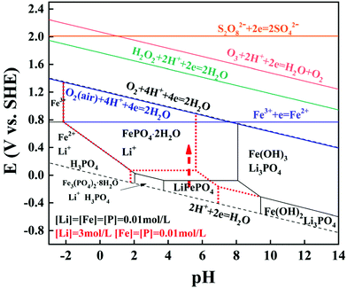 | ||
| Fig. 1 E-pH diagram of the Li–Fe–P-H2O system and the relationship between the electrode potential of redox couples and pH (25 °C). | ||
In addition, the relationship between the redox potentials of various redox couples for common oxidants and pH is presented in Table S4† and Fig. 1. The redox potentials for most common oxidants linearly increase (except Fe3+) as the pH value decreases, suggesting that the oxidizing ability is stronger at a lower pH. The redox potentials of all the oxidants are higher than the theoretical oxidative potential of LiFePO4 to FePO4, which can interpret well why lithium should be selectively recovered from the spent LFP by H2O2, Fe2(SO4)3, Na2S2O8, etc. In particular, the redox potential of air is 1.218 V at 25 °C, which is slightly lower than pure O2. Hence, LFP can be oxidized by air in thermodynamics and the corresponding reaction is presented as eqn (2).
| 4LiFePO4 + O2(air) + 4H+ = 4Li+ + 2H2O + 4FePO4 | (2) |
3.2 Leaching behavior in the air oxidation–water leaching process
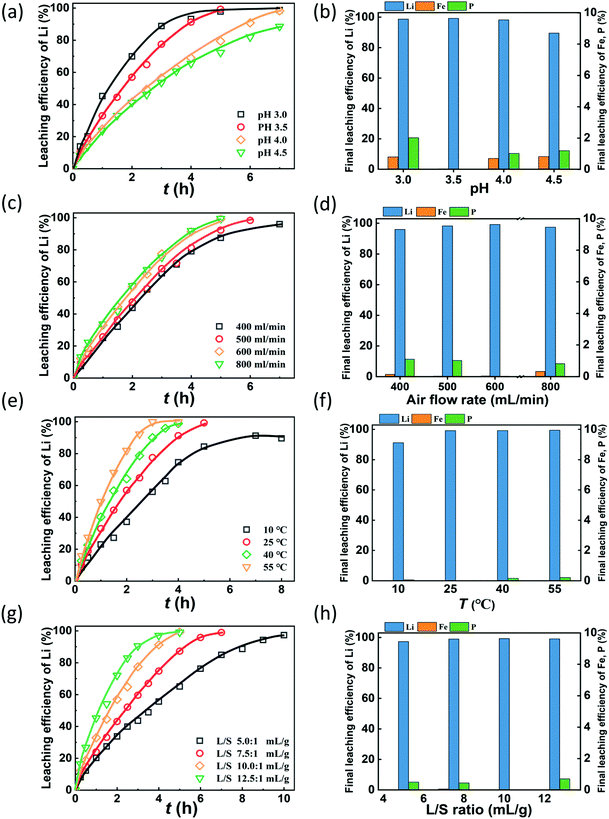
The pH value is expected to play a key role in lithium recovery via the air oxidation–water leaching process since the oxidative ability of air is closely related to pH. Fig. 2(a) shows that the leaching efficiencies of Li increase with time at different rates as the pH varies. Obviously, the leaching rate is faster with the decrease of pH. The required time for leaching 95% of lithium was determined by the kinetic curves under various leaching conditions (Fig. S2†). This indicates that the required time for leaching 95% lithium is 4.0, 4.2, 6.5, and 9 h at pH values of 3.0, 3.5, 4.0, and 4.5, respectively. The reason is that the oxidizing ability of air is stronger at a lower pH, which can be derived from thermodynamic calculation. Fig. 2(b) shows the final leaching efficiency of Li, Fe and P, and it shows that the leaching efficiency of lithium exceeds 98% at pH 3.0, 3.5 and 4.0, while it decreases to 89.5% at pH 4.5. The leaching efficiencies of Fe and P are lower than 2% at the investigated pH. This suggests that a sound effect of selective extraction of lithium from LFP can be obtained by air oxidation–water leaching. Considering the leaching rate, efficiency of lithium and the consumption of sulfuric acid, the optimal pH value is selected to be 3.5, and under these conditions, the leaching efficiencies of Li, Fe and P are 99.3%, 0.02% and 0.02%, respectively, and the molar dosage of H2SO4 is 0.51 times the Li molar amount in the raw material.Air is the oxidant to oxidize LFP and the air flow rate is a significant parameter in this gas–liquid–solid reaction system. The air flow rate investigated ranges from 400 mL min−1 to 800 mL min−1 to identify a suitable flow rate to oxidize LFP. As shown in Fig. 2(c), the leaching efficiency of Li increases with time at a different speed as the air flow rate varies. When the air flow rate increases from 400 mL min−1 to 600 ml min−1, the leaching of lithium accelerates since the amount of active oxygen increases33–35 and the stirring effect also enhances. However, when the air flow rate further increases to 800 mL min−1, the promotion of the leaching rate is not significant. This tendency of the lithium leaching rate is consistent with the required times for leaching 95% of lithium, which are 5.4, 5.2, 4.2, 4.1 h at air flow rates from 400 mL min−1 to 800 mL min−1. Fig. 2(d) shows the final leaching efficiencies of Li, Fe and P under various air flow rates. The final leaching efficiencies of lithium increases slightly upon increasing the air flow rates, while the dissolution of Fe and P is relatively low. Since more energy will be consumed as the air flow rate increases, the optimal air flow rate is chosen to be 600 mL min−1.
To investigate the effect of temperature on the leaching kinetic behavior of lithium, a series of experiments were performed at 10 °C, 25 °C, 40 °C and 55 °C, Fig. 2(e) shows that the leaching rate of lithium is significantly higher upon increasing the temperature and the required time for 95% of lithium leaching reduces from 8 h at 10 °C to 2.7 h at 55 °C (Fig. S2†). Since the amount of reactive oxygen in the solution increases with the temperature,36,37 the oxidation reaction is accelerated. The final leaching efficiencies of lithium are 91.2%, 99.3%, 99.3%, and 99.5% at 10 °C, 25 °C, 40 °C, and 55 °C, respectively. When the reaction temperature exceeds 25 °C, the final leaching efficiency of lithium does not change significantly. The leaching efficiencies of Fe and P are all less than 0.02% at the investigated temperatures (Fig. 2(f)), illustrating that the effect of temperature on the leaching of Fe and P can be neglected. Thus, the optimized temperature is 25 °C.
Fig. 2(g) shows that the leaching efficiency of lithium increases at different rates under various L/S ratios. The leaching rate is enhanced with the increase of the L/S ratio. It takes 9.2, 5.8, 4.2, and 3.6 h to extract 95% of lithium from the LFP when the L/S ratios are 5, 7.5, 10, and 12.5 mL g−1. The decreased viscosity of the slurry and the enhanced stirring effect at a high L/S ratio can be responsible for the acceleration of the leaching reaction.38,39 Additionally, the leached Li and Fe are not affected by the changes in the L/S ratio. The final leaching efficiencies of Li are all higher than 97% and those of Fe are lower than 0.02%. The concentration of lithium in the solution becomes low at a high L/S ratio, which means more energy and time are required to condense the lithium concentration. Thus, an L/S ratio of 10![[thin space (1/6-em)]](https://www.rsc.org/images/entities/char_2009.gif) :
:![[thin space (1/6-em)]](https://www.rsc.org/images/entities/char_2009.gif) 1 was chosen to be optimal.
1 was chosen to be optimal.
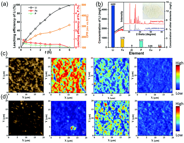
Fig. 3(a) shows the leaching behaviors of Li, Fe, P and redox potential under the optimal leaching conditions. The oxidation potential increases from 150 mV at 15 min to 313 mV at 5 h, which is higher than the theoretical potential for oxidizing LiFePO4 to FePO4. A little Fe and P are leached in the initial stage, which then decrease gradually while almost all the lithium can be leached. The concentrations of Fe, P and Li are 2.75 mg L−1, 2.11 mg L−1 and 4400 mg L−1 in the final leachate (Fig. 3b), indicating that lithium can be leached with high selectivity using the air oxidation and water leaching method. The concentrations of other impurities Al, Cu and F are also low and the leachate can be employed to precipitate Li2CO3 directly without any purification process. From the XRD pattern of the Li2CO3 product, there are no other phases, indicating that a high purity of Li2CO3 is obtained.
Fig. S3† shows the SEM images of the spent LFP material and leaching residue, indicating that the particle size and morphology of the leaching residue are nearly unchanged compared with the raw LFP material. In particular, the distribution of Li, Fe, and P in the spent LFP material and leaching residue was analyzed by TOF-SIMS (Fig. 3c and d). The signals of Li are strong and those of Li, Fe, and P are uniformly distributed in the spent LFP material. After delithiation, the signals of Li almost disappear and Fe and P remain unessentially unchanged, demonstrating that Li is selectively extracted into the solution via air oxidation–water leaching.
3.3 Lithium leaching kinetics
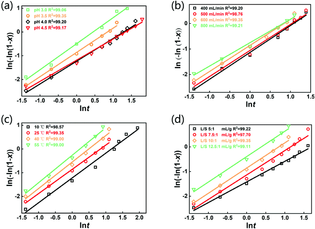
The selective leaching of Li from the spent LFP batteries is involved with a gas–liquid–solid heterogeneous reaction. Until now, the Avrami equation has been widely adopted to interpret the leaching kinetic data of various gas–solid–liquid reactions.40–42 The equation was initially developed for crystallization kinetics in solution and leaching can be regarded as the reverse process of crystallization. The Avrami equation used in this study is as follows:ln((−ln(1 − x)) = ln![[thin space (1/6-em)]](https://www.rsc.org/images/entities/char_2009.gif) k + n k + n![[thin space (1/6-em)]](https://www.rsc.org/images/entities/char_2009.gif) ln ln![[thin space (1/6-em)]](https://www.rsc.org/images/entities/char_2009.gif) t t | (3) |
![[thin space (1/6-em)]](https://www.rsc.org/images/entities/char_2009.gif) k based on the leaching kinetic data in Fig. 2. Fitting degrees of higher than 0.97 for all the kinetical curves demonstrate that the leaching kinetic behavior of Li fits well with the Avrami model. Furthermore, the kinetical parameters of n and k under various conditions are shown in Tables S5–S8.† The values of k increase with the decrease of pH and the increase of the air flow rate, temperature and L/S ratio, which are consistent with the change in the lithium leaching rate with the parameters in Fig. 2. Additionally, the Arrhenius formula (eqn (4)) was employed to estimate the activation energy of the leaching reactions.
k based on the leaching kinetic data in Fig. 2. Fitting degrees of higher than 0.97 for all the kinetical curves demonstrate that the leaching kinetic behavior of Li fits well with the Avrami model. Furthermore, the kinetical parameters of n and k under various conditions are shown in Tables S5–S8.† The values of k increase with the decrease of pH and the increase of the air flow rate, temperature and L/S ratio, which are consistent with the change in the lithium leaching rate with the parameters in Fig. 2. Additionally, the Arrhenius formula (eqn (4)) was employed to estimate the activation energy of the leaching reactions. | (4) |
3.4 Mechanism of the selective leaching of lithium
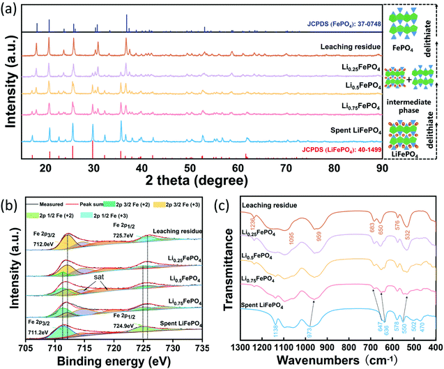
Three solid samples were prepared from the spent LFP with lithium leaching efficiency of 25%, 50% and 75% under the optimal experimental conditions, which were denoted as Li0.75FePO4, Li0.5FePO4, Li0.25FePO4, respectively. Fig. 5(a) shows the XRD patterns and the crystal structure of these leaching products and cathode materials before and after complete leaching. All diffraction peaks of the raw spent cathode match well with the standard pattern of LiFePO4 (JCPDS 40-1499). It can be obviously observed that the intensity of the characteristic peaks of LFP diminishes gradually while that of FePO4 enhances with the lithium extraction from the spent LFP. The characteristic diffraction peaks of the leaching residue can be indexed to the heterosite FePO4 (JCPDS 37-0748), which has an orthorhombic olivine structure.25 Interestingly, the phase change in the air oxidation process is similar to that of the LFP cathode material in the charging process of the battery.43 The above results all demonstrate that Li is selectively released from LFP to the leachate without destroying the olivine structure during air oxidation leaching.
Fig. 5(b) shows the XPS spectrum of Fe of the spent LFP and leaching products with various lithium leaching efficiencies. The peaks located at 711.2 eV and 724.9 eV are the characteristic peaks of Fe2+ in the region of 2p3/2 and 2p1/2 in the spent cathode.44,45 The characteristic peaks of Fe3+ located at 712.0 eV and 725.7 eV appear in Li0.75FePO4 and gradually increase with further delithiation.31,45 Moreover, the XPS peak area ratios of Fe3+ to Fe2+ in Li0.75FePO4, Li0.5FePO4 and Li0.25FePO4 are calculated, and the results are exactly 1![[thin space (1/6-em)]](https://www.rsc.org/images/entities/char_2009.gif) :
:![[thin space (1/6-em)]](https://www.rsc.org/images/entities/char_2009.gif) 3, 1
3, 1![[thin space (1/6-em)]](https://www.rsc.org/images/entities/char_2009.gif) :
:![[thin space (1/6-em)]](https://www.rsc.org/images/entities/char_2009.gif) 1 and 3
1 and 3![[thin space (1/6-em)]](https://www.rsc.org/images/entities/char_2009.gif) :
:![[thin space (1/6-em)]](https://www.rsc.org/images/entities/char_2009.gif) 1, which reflect the simultaneity between Fe oxidation and Li leaching. Finally, the characteristic peaks of Fe2+ are not detected in the XPS spectrum of the leaching residue, but the peaks of Fe3+ are clearly observed, suggesting the complete conversion from LiFePO4 to FePO4.
1, which reflect the simultaneity between Fe oxidation and Li leaching. Finally, the characteristic peaks of Fe2+ are not detected in the XPS spectrum of the leaching residue, but the peaks of Fe3+ are clearly observed, suggesting the complete conversion from LiFePO4 to FePO4.
Fig. 5(c) shows the FT-IR spectrum of the spent LFP and leaching products with various lithium leaching efficiencies. The characteristic band of olivine FePO4 at 1236 cm−1 (ref. 46) can be clearly observed in leaching products, which is not shown in the spent LFP cathode. The basic feature of the selective leaching of lithium is that upon delithiation, the valence state of iron and the lattice parameters have been changed, leading to a small change in the vibration frequency of IR spectra. For instance, the band of the symmetric stretching mode of PO43− at 973 cm−1 in LiFePO4 gradually shifts to 959 cm−1 in FePO4.47,48 The bands at 636 cm−1 and 647 cm−1 assigned to the vibration modes of octahedral FeO6 in LiFePO4 are shifted to 649 cm−1 and 683 cm−1 in the residue. In the region of bend modes of tetrahedral PO4, the bands at 578 cm−1 and 550 cm−1 shift to 576 cm−1 and 532 cm−1.46 In addition, the bands at 502 cm−1 and 470 cm−1 are associated with the motion of lithium ions and their intensities are diminished with the decrease of x in LixFePO4.48 Overall, the selective leaching of Li from LiFePO4 will not destroy the framework composed of octahedral FeO6 and the tetrahedral PO4 in the olivine structure, which is consistent with the results of the XRD analysis.
AC-TEM analysis was carried out to observe the microscopic morphology and structure of the spent LFP and the leaching residue. It can be observed from Fig. 6 that a layer of amorphous carbon is covered on the surface of the LFP material. The interplanar spacing of 5.187 Å can be calculated from Fig. 6(a), which corresponds to the (020) crystal surface of olivine LiFePO4. The different interplanar spacing of 4.854 Å in the image of the residue (Fig. 6b) corresponds to the (020) crystal surface of olivine FePO4. The results indicate that Li is extracted completely from LiFePO4 and the olivine structure remains unchanged.
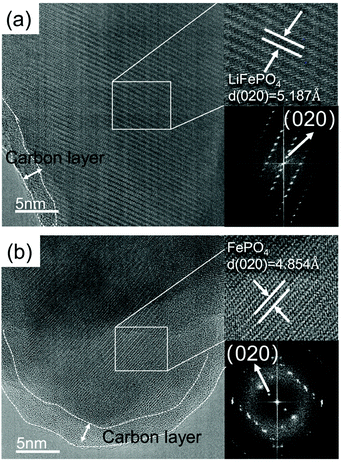 | ||
| Fig. 6 AC-TEM image of the (a) spent LFP material and (b) leaching residue (pH 3.5, 600 mL min−1 air flow rate, 10 mL g−1 L/S ratio and 25 °C). | ||
Based on the results of the above characterization, the mechanism of selective lithium recovery from the spent LFP material by air oxidation and water leaching can be clarified. LiFePO4 is oxidized by oxygen in the air and O2 is converted to OH−. H2SO4 is employed to neutralize the generated OH− to maintain a low pH so that the air can have strong oxidability. The oxidation of iron and the deintercalation of lithium take place simultaneously. So, the ratio of the FePO4 phase to the LiFePO4 phase gradually increases in the lithium leaching course. The phase change of LFP in the air oxidation process is similar to that in battery charging, except for the substitution of the organic electrolyte by the aqueous electrolyte. This mechanism can well explain the high leaching efficiency of Li via the air oxidation leaching method. First, the oxidation potential provided by the air is higher than that of LiFePO4/FePO4, but the redox reaction is still located in the stable area of H2O. Secondly, the stable olivine structure of the LFP material allows Li to be efficiently extracted from the retired cathode under an oxidation potential.
3.5 Performance of regenerated LiFePO4
A regenerated LFP cathode material was prepared by using the recovered Li2CO3 and leaching residue as the raw materials via the conventional high-temperature solid method. Fig. S5† shows the XRD pattern of the regenerated LFP material. It suggests that the peaks are indexed to LiFePO4 (JCSPD 40-1499) and there are no other peaks of impurities. The electrochemical performances of the regenerated material are shown in Fig. 7. Fig. 7(a) shows the redox peaks of the cyclic voltammetry (CV) curve, which are highly symmetric, implying the good reversibility performance of the regenerated material for the insertion and extraction of lithium ions. The rate performance is shown in Fig. 7(b); the specific capacities of the regenerated material are 148.8, 142, 131, 114.5, and 149.0 mA h g−1 at 0.2, 0.5, 1, 2, and 0.2C (1C = 170 mA g−1), respectively. It can be observed from Fig. 7(c) that the regenerated material presents good cycling performance. The specific capacity is 131.7 mA h g−1 after 100 cycles and the capacity retention is 99.0%. From the above results, the regenerated material exhibits sound electrochemical performance. So, using the proposed method, not only lithium can be recovered as the high purity Li2CO3 and the leaching residue can be used to re-prepare the LFP material for applying in energy storage, low-speed EVs, etc.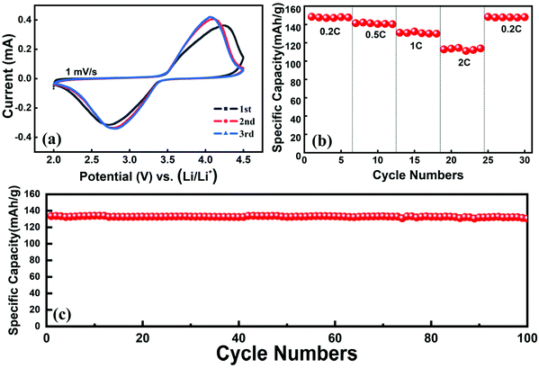 | ||
| Fig. 7 The electrochemical performance of the regenerated LFP material: (a) cyclic voltammetry curve, (b) rate performance and (c) cycling performance at 1C rate. | ||
3.6 Economic and environmental analysis of the proposed technology
A preliminary economic analysis is performed for recycling 1 ton of the spent LFP cathode powders by the proposed method in China. The prices of all the reagents and products are according to the latest data on the Internet and the calculations are presented in the ESI in detail (shown in Table S9).†Fig. 8 shows the flow chart of the proposed method and preliminary economic analysis for recycling 1 ton of the spent LFP material. The spent LFP cathode material was purchased from a local lithium-ion battery recycling company and it cost $1406.3. According to the calculation, the amounts of reagents H2SO4 and Na2CO3 consumed are 322.1 kg and 358.4 kg and the production amounts of Li2CO3, FePO4 and Na2SO4·10H2O are 233.6 kg, 960 kg and 1022.7 kg. The energy consumed is converted to electrical energy and the total consumption is 1706 kW h. Except for the reagents and energy consumption, the cost also includes labor, equipment depreciation and maintenance. Finally, the total profit for the recycling of 1-ton cathode powders is calculated to be $2030.1. The technologies for selective lithium recovery in the available literature are shown in Table S10.† Compared to these technologies, the much cheaper air is employed as the oxidant and pretreatment of the LFP cathode (e.g., high-temperature conversion, mechanical activation) is not required, indicating a higher economic efficiency of the proposed new method.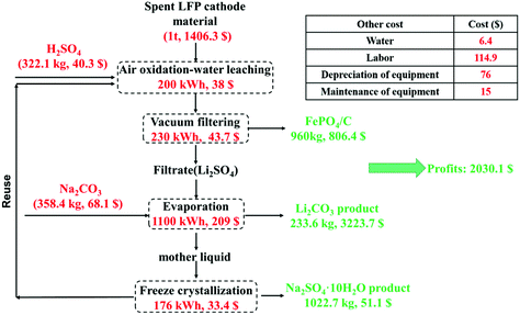 | ||
| Fig. 8 Flow chart of the proposed method and preliminary economic analysis for recycling 1 ton of the spent LFP cathode material. | ||
Overall, by the air oxidation leaching method, the most valuable element lithium can be efficiently recovered as high purity Li2CO3. Moreover, all the procedures are simple and can be performed using easily available equipment and economical reagents.
For the environmental benefits of this new technology, the replacement of strong oxidants by renewable and clean air avoids the resource consumption and generation of secondary wastes. The solution can be recycled after freeze crystallization of the Na2SO4·10H2O product and the leaching residue of FePO4 can be used to prepare pristine LFP. The closed-loop route makes nearly no generation of wastewater and solid waste, in line with the principles and targets of green chemistry. These advantages allow the proposed method to be promising in industrial production and will contribute to the sustainable development of LFP batteries.
4. Conclusion
A facile, efficient and economical process was proposed for the selective recovery of lithium from the spent LiFePO4 material via water leaching, where the air was used as the oxidant. 99.3% of Li is leached into the solution under optimized conditions (pH 3.5, air flow rate of 600 mL min−1, 25 °C, L/S ratio of 10 g mL−1 and 5 h), while the leaching efficiencies of Fe and P were both 0.02%. A high-purity Li2CO3 product can be obtained from the leachate directly without purification. The leaching kinetics of lithium leaching fits well with the Avrami model and the process is controlled by diffusion. The characterization results show that the oxidation of iron and the deintercalation of lithium take place simultaneously and the ratio of the FePO4 phase to LiFePO4 phase gradually increases in the lithium leaching course. The phase change of LFP in the air oxidation process is similar to that in battery charging. The regenerated LFP cathode material using the leaching residue of FePO4 exhibits good electrochemical performance. The total profit for the recycling 1-ton cathode powders is calculated to be $2030.1. The whole process is found to be in line with the principles of green chemistry and has great potential for industrial-scale recycling of spent LFP batteries. Our findings may also have general implications in the green recycling of hazardous wastes.Conflicts of interest
The authors declare no competing financial interest.Acknowledgements
This paper was supported by the Guangdong Key Area R&D Program (2020B090919003), the National Natural Science Foundation of China (No. 51834008, 51874040, 52034002, U1802253), and the Fundamental Research Funds for the Central Universities (No. FRF-GF-20-02B).References
- J. B. Goodenough and K. S. Park, J. Am. Chem. Soc., 2013, 135, 1167–1176 CrossRef CAS PubMed.
- A. Ritchie and W. Howard, J. Power Sources, 2006, 162, 809–812 CrossRef CAS.
- Z. R. Xu, L. B. Gao, Y. J. Liu and L. Li, J. Electrochem. Soc., 2016, 163, A2600–A2610 CrossRef CAS.
- H. Omar and S. Rohani, Front. Chem. Sci. Eng., 2015, 9, 15–32 CrossRef CAS.
- D. Qiao, G. Wang, T. Gao, B. Wen and T. Dai, Sci. Total Environ., 2021, 764, 142835 CrossRef CAS PubMed.
- W. Wang and Y. Wu, Resour., Conserv. Recycl., 2017, 127, 233–243 CrossRef.
- X. Li, J. Zhang, D. Song, J. Song and L. Zhang, J. Power Sources, 2017, 345, 78–84 CrossRef CAS.
- J. Li, Y. Wang, L. Wang, B. Liu and H. Zhou, J. Mater. Sci.: Mater. Electron., 2019, 30, 14580–14588 CrossRef CAS.
- W. Song, J. Liu, L. You, S. Wang, Q. Zhou, Y. Gao, R. Yin, W. Xu and Z. Guo, J. Power Sources, 2019, 419, 192–202 CrossRef CAS.
- Q. Sun, X. Li, H. Zhang, D. Song, X. Shi, J. Song, C. Li and L. Zhang, J. Alloys Compd., 2020, 818, 153292 CrossRef CAS.
- Q. Jing, J. Zhang, Y. Liu, W. Zhang, Y. Chen and C. Wang, ACS Sustainable Chem. Eng., 2020, 8, 17622–17628 CrossRef CAS.
- P. Xu, Q. Dai, H. Gao, H. Liu, M. Zhang, M. Li, Y. Chen, K. An, Y. S. Meng, P. Liu, Y. Li, J. S. Spangenberger, L. Gaines, J. Lu and Z. Chen, Joule, 2020, 4, 2609–2626 CrossRef CAS.
- Z. Yang, J. Zhang, Q. Wu, L. Zhi and W. Zhang, J. Chin. Ceram. Soc., 2013, 41, 1051–1056 CAS.
- P. Yadav, C. J. Jie, S. Tan and M. Srinivasan, J. Hazard. Mater., 2020, 399, 123068 CrossRef CAS.
- E. Fan, L. Li, X. Zhang, Y. Bian, Q. Xue, J. Wu, F. Wu and R. Chen, ACS Sustainable Chem. Eng., 2018, 6, 11029–11035 CrossRef CAS.
- R. Zheng, L. Zhao, W. Wang, Y. Liu, Q. Ma, D. Mu, R. Li and C. Dai, RSC Adv., 2016, 6, 43613–43625 RSC.
- X. Wang, X. Wang, R. Zhang, Y. Wang and H. Shu, Waste Manage., 2018, 78, 208–216 CrossRef CAS.
- Y. Song, L. He, Z. Zhao and X. Liu, Sep. Purif. Technol., 2019, 229, 115823 CrossRef CAS.
- D. Bian, Y. Sun, S. Li, Y. Tian, Z. Yang, X. Fan and W. Zhang, Electrochim. Acta, 2016, 190, 134–140 CrossRef CAS.
- Y. Yang, X. Zheng, H. Cao, C. Zhao, X. Lin, P. Ning, Y. Zhang, W. Jin and Z. Sun, ACS Sustainable Chem. Eng., 2017, 5, 9972–9980 CrossRef CAS.
- Y. Dai, Z. Xu, D. Hua, H. Gu and N. Wang, J. Hazard. Mater., 2020, 396, 122707 CrossRef CAS.
- J. Zhang, J. Hu, Y. Liu, Q. Jing, C. Yang, Y. Chen and C. Wang, ACS Sustainable Chem. Eng., 2019, 7, 5626–5631 CrossRef CAS.
- H. Li, S. Xing, Y. Liu, F. Li, H. Guo and G. Kuang, ACS Sustainable Chem. Eng., 2017, 5, 8017–8024 CrossRef CAS.
- Y. Yang, X. Meng, H. Cao, X. Lin, C. Liu, Y. Sun, Y. Zhang and Z. Sun, Green Chem., 2018, 20, 3121–3133 RSC.
- Q. Jing, J. Zhang, Y. Liu, C. Yang, B. Ma, Y. Chen and C. Wang, J. Phys. Chem. C, 2019, 123, 14207–14215 CrossRef CAS.
- J. Kumar, X. Shen, B. Li, H. Liu and J. Zhao, Waste Manage., 2020, 113, 32–40 CrossRef CAS.
- S. Tao, J. Li, L. Wang, L. Hu and H. Zhou, Ionics, 2019, 25, 5643–5653 CrossRef CAS.
- K. Liu, Q. Tan, L. Liu and J. Li, Environ. Sci. Technol., 2019, 53, 9781–9788 CrossRef CAS PubMed.
- K. Liu, L. Liu, Q. Tan and J. Li, Green Chem., 2021, 23, 1344–1352 RSC.
- J. Yu, X. Wang, M. Zhou and Q. Wang, Energy Environ. Sci., 2019, 12, 2672–2677 RSC.
- Z. Li, D. Liu, J. Xiong, L. He, Z. Zhao and D. Wang, Waste Manage., 2020, 107, 1–8 CrossRef CAS PubMed.
- B. Zhang, X. Qu, J. Qu, X. Chen, H. Xie, P. Xing, D. Wang and H. Yin, Green Chem., 2020, 22, 8633–8641 RSC.
- F. Y. Ushikubo, T. Furukawa, R. Nakagawa, M. Enari, Y. Makino, Y. Kawagoe, T. Shiina and S. Oshita, Colloids Surf., A, 2010, 361, 31–37 CrossRef CAS.
- A. Agarwal, W. J. Ng and Y. Liu, Chemosphere, 2011, 84, 1175–1180 CrossRef CAS PubMed.
- X. Yu, Z. Wang, Y. Lv, S. Wang, S. Zheng, H. Du and Y. Zhang, J. Chem. Technol. Biotechnol., 2017, 92, 1738–1745 CrossRef CAS.
- S. S. Behera and P. K. Parhi, Sep. Purif. Technol., 2016, 160, 59–66 CrossRef CAS.
- L. Liu, Z. Wang, H. Du, S. Zheng, U. Lassi and Y. Zhang, Int. J. Miner. Process., 2017, 160, 1–7 CrossRef CAS.
- M. K. Jha, A. Kumari, A. K. Jha, V. Kumar, J. Hait and B. D. Pandey, Waste Manage., 2013, 33, 1890–1897 CrossRef CAS.
- L. Li, W. Qu, X. Zhang, J. Lu, R. Chen, F. Wu and K. Amine, J. Power Sources, 2015, 282, 544–551 CrossRef CAS.
- J. Hancock and J. Sharp, J. Am. Ceram. Soc., 1972, 55, 74–77 CrossRef CAS.
- J. Málek, Thermochim. Acta, 1995, 267, 61–73 CrossRef.
- J. L. Zhang, J. T. Hu, W. J. Zhang, Y. Q. Chen and C. Y. Wang, J. Cleaner Prod., 2018, 204, 437–446 CrossRef CAS.
- J. Feng, N. A. Chernova, F. Omenya, L. Tong, A. C. Rastogi and M. S. Whittingham, J. Solid State Electrochem., 2018, 22, 1063–1078 CrossRef CAS.
- S. J. Rajoba, L. D. Jadhav, R. S. Kalubarme, P. S. Patil, S. Varma and B. N. Wani, Ceram. Int., 2018, 44, 6886–6893 CrossRef CAS.
- Y. Guan, J. Shen, X. Wei, Q. Zhu, X. Zheng, S. Zhou and B. Xu, Electrochim. Acta, 2019, 294, 148–155 CrossRef CAS.
- A. A. Salah, P. Jozwiak, K. Zaghib, J. Garbarczyk, F. Gendron, A. Mauger and C. M. Julien, Spectrochim. Acta, Part A, 2006, 65, 1007–1013 CrossRef PubMed.
- C. M. Burba and R. Frech, J. Electrochem. Soc., 2004, 151, A1032–A1038 CrossRef CAS.
- P. Jozwiak, J. E. Garbarczyk, M. Wasiucionek, I. Gorzkowska, F. Gendron, A. Mauger and C. M. Julien, Solid State Ionics, 2008, 179, 46–50 CrossRef CAS.
Footnote |
| † Electronic supplementary information (ESI) available: Table S1: The main operating parameters for ICP-OES analysis; Tables S2 and S3: Thermodynamic equilibrium calculations of the Li-Fe–P-H2O system; Table S4: Standard electrode potential for some electrical couples in aqueous solution; Tables S5–S8: Parameters of the Avrami model for leaching of Li; Table S9: Economic analysis for recycling 1 ton of the spent LFP cathode material; Table S10: Summary of different processes for the selective extraction of Li from LFP; Fig. S1: The experimental procedure of the air oxidation-water leaching method; Fig. S2: Required time of 95% lithium leaching rate from the spent LFP cathode under different conditions; Fig. S3: Arrhenius plot for the air oxidation leaching of Li from 10 °C to 55 °C; Fig. S4: SEM images of the spent LFP cathode and leaching residue, and preliminary economic analysis; and Fig. S5: XRD pattern of the regenerated LFP material. See DOI: 10.1039/d1gc03333f |
| This journal is © The Royal Society of Chemistry 2022 |

