 Open Access Article
Atomistic insights of a chemical complexity effect on the irradiation resistance of high entropy alloys†
Lingyun
Qian
a,
Honggang
Bao
a,
Rui
Li
 *a and
Qing
Peng
 *bc
*bc
aSchool of Mechanical Engineering, University of Science and Technology Beijing, Beijing, 100083, China. E-mail: lirui@ustb.edu.cn
bPhysics Department, King Fahd University of Petroleum and Minerals, Dhahran 31261, Saudi Arabia. E-mail: qing.peng@kfupm.edu.sa
cK.A.CARE Energy Research & Innovation Center at Dhahran, Dhahran, 31261, Saudi Arabia
First published on 21st December 2021
Abstract
High irradiation tolerance is a key feature required for designing structural materials for next-generation nuclear reactors, for which high entropy alloys (HEAs) and equiatomic multicomponent single-phase alloys are good candidates. In this paper, the effect of chemical complexity on irradiation resistance is investigated using molecular dynamics simulations. Taking the classical Cantor alloy CoCrFeMnNi as a paradigm, we have studied the number of defects, the size of defect clusters and dislocation of six FCC materials, pure Ni, FeNi, CrFeNi, CoCrFeNi, CoCrCuFeNi and CoCrFeMnNi, under consecutive bombardment. The fewest defects can be observed in two HEAs, and so can the size of defect clusters. Multicomponent alloys also show better performance in terms of irradiation resistance than pure Ni. The reason can be attributed to the complexity of high entropy alloys and multicomponent alloys, which leads to lattice distortion and hysteresis diffusion effects. The longest and shortest dislocation lengths are observed in CoCrCuFeNi and CoCrFeMnNi. A larger number of stacking faults is observed in CoCrCuFeNi. The fewer defects and dislocations of CoCrFeMnNi indicate its promising applications in nuclear structural materials.
1. Introduction
Nuclear energy is one of the main power resources driving modern civilization and the future.1 One of the main challenges of the utilization of nuclear energy is for structural materials that have high-dose radiation tolerance. During the operation of nuclear reactors, high-energy particles bombard structural materials, leading to a large number of defects in materials,2 including dislocation and surface defects.3 The damage caused by irradiation is the key factor behind the failure of structural materials.4–6 The development of fourth-generation nuclear reactors requires materials with high irradiation resistance.7,8 High entropy alloys (HEAs) and equiatomic multicomponent (EAMCs) alloys are among the candidates and have attracted attention.HEAs are a type of alloys formed by five or more equal or approximately equal amounts of metallic elements.9–11 The definition of EAMCs is similar, but they usually have a smaller number of types of constituent elements than HEAs. It has been confirmed that many multicomponent alloys and high entropy alloys have excellent mechanical properties, good wear resistance,12,13 structural stability14,15 and corrosion resistance.16,17 Alloys consisting of Co, Cr, Fe, Ni, Mn, Cu elements are one kind. Gludovatz et al.18 showed that due to strain hardening, CoCrNi alloy could achieve excellent damage resistance at low temperatures, which implied a good combination of strength, ductility and fracture toughness. Wu et al.19 indicated that some alloys (e.g. CoCrNi, CoCrMnNi and CoCrFeNi) exhibited yields and ultimate strength that increased strongly with decreasing temperature, while others (e.g. CoNi and Ni) exhibited very weak temperature dependency. Buluc et al.20 measured the hardness and friction properties of non-equivalent AlCrFeMnNi high entropy alloys through experiments. Ye et al.21 found that CoCrFeMnNi had excellent corrosion resistance, which was higher than that of A36 steel substrate and similar to that of 304 stainless steel. Chen Zhen et al.22 reported that compared to Al0.75CrCoFeNi, the removal of the Co element decreased the strength, hardness and ductility. With the addition of Ti, Al0.75CrCoFeNiTi0.25 had higher hardness and strength. The results showed that the addition of different elements influenced the alloy properties, helping to design high entropy alloys.
EAMCs and HEAs in general have better radiation resistance than pure metals or conventional alloys.23,24 This could be attributed to their lattice distortion and sluggish diffusion effects,25–28 which reduce the migration and diffusion of defects. Wang et al.29 studied the irradiation of CoCrCuFeNi HEA under different doses of He+ ion beams. Kumar et al.30 investigated the radiation resistance of CrFeMnNi and FeCrNi. The results showed that the introduction of Mn enhanced the radiation resistance of the material. Do et al.31 indicated that the origin of high resistance to irradiation in the CoCrFeMnNi HEA was lattice distortion, which was caused by the complexity of the alloy. Lu et al.32 found that the enhanced swelling resistance of FeNi, CoFeNi, CoCrFeNi and CoCrFeMnNi could be attributed to a change in tailored interstitial defect cluster motion, which enhanced the recombination of point defects. Li et al.33 indicated that CoCrFeMnNi had stronger resistance to surface bombardment. Xia et al.34 pointed out that AlxCoCrFeNi (x = 0.1, 0.75 and 1.5) had a lower volume swelling rate under high-dose irradiation than other commonly used radiation-resistant materials, such as M316 stainless steel or pure zirconium. Granberg et al.35,36 compared the defects in pure Ni, FeNi, CoFeNi and CoCrNi under high-energy ion irradiation. They indicated that defect accumulation was related to the difference in edge dislocation mobility, and the irradiation damage did not necessarily decrease with an increase in the amount of complexity in the alloys.
Despite these studies, the influence of elements in alloys on irradiation resistance is still elusive, especially in the range from a medium entropy alloy to a high entropy alloy. In this work, we have investigated the irradiation resistance of Ni, FeNi, CrFeNi, CoCrFeNi, CoCrCuFeNi and CoCrFeMnNi, in increasing order of chemical complexity, in a single-phase FCC structure under multiple cascading collisions by molecular dynamics simulation. The results are helpful for the design of irradiation-resistant materials.
2. Model and methods
Molecular dynamics simulation is a well-established and suitable approach for the study of displacement cascades in radiation damage.3 The atomistic models of Ni, FeNi, CrFeNi, CoCrFeNi, CoCrCuFeNi and CoCrFeMnNi are illustrated in Fig. 1. The total number of atoms in each model is 32![[thin space (1/6-em)]](https://www.rsc.org/images/entities/char_2009.gif) 000. The length is 7.05 nm along the x, y, and z directions. A periodic boundary condition is applied in each direction. The proportions of the elements are equal in each alloy. The atoms of each element are randomly distributed. Since these six materials all contain Ni atoms, Ni atoms inside the models are randomly selected as primary knock-on atoms (PKA) in this paper. The direction of velocity is random while its magnitude is determined by the PKA energy.
000. The length is 7.05 nm along the x, y, and z directions. A periodic boundary condition is applied in each direction. The proportions of the elements are equal in each alloy. The atoms of each element are randomly distributed. Since these six materials all contain Ni atoms, Ni atoms inside the models are randomly selected as primary knock-on atoms (PKA) in this paper. The direction of velocity is random while its magnitude is determined by the PKA energy.
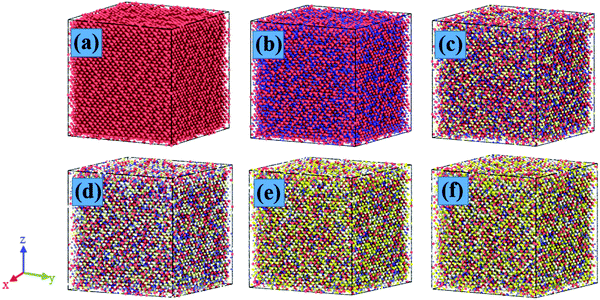 | ||
| Fig. 1 Illustration of six FCC materials. (a–f) are Ni, FeNi, CrFeNi, CoCrFeNi, CoCrCuFeNi and CoCrFeMnNi, respectively. | ||
The interatomic interactions of CoCrCuFeNi are described by the EAM potential.37 The short-range interaction of atomic collisions in the cascade process is described by the ZBL potential.38 The interatomic interactions in CoCrFeMnNi are described by the 2NN MEAM potential.39 Meanwhile, two parameters are adjusted in order to describe the short-range interatomic interaction in high-energy atomic collisions in cascades correctly. This change has been confirmed by Do et al.31 to be sufficient, and so the effect on the fitted physical properties could be ignored.
The MD simulations use the LAMMPS package.40 The systems are annealed before conducting bombardment simulation. The ensemble is NPT with a timestep of 0.001 ps. The following are the details of the annealing process. First, the simulation systems relax at room temperature 300 K for 100 ps. Then a temperate gradient of 3.4 K ps−1 is applied to increase the temperature to 2000 K. The temperature of 2000 K is held for 1000 ps for relaxation and equilibrium. Finally, the same temperature gradient is applied to decrease the temperature to 300 K. The NVE ensemble is applied in the simulation of irradiation.
An adaptive time step is applied because the movement of atoms in a step should be controlled to within 0.002 nm. The energy dissipation during the bombardment process is achieved by applying a Berendsen thermostat41 to the boundary atoms within 0.5 nm. The temperature is 300 K. The simulation systems relax for 2000 ps at room temperature to make sure that the systems reach equilibrium before the bombardment process starts. The PKA energy of Ni atoms is 3000 eV,33 which is selected because it can cause a reasonable ratio of defects in the matrix.42 The six models are all bombarded 500 times. After each bombardment, 50![[thin space (1/6-em)]](https://www.rsc.org/images/entities/char_2009.gif) 000 steps of relaxation are conducted before the next bombardment, which is sufficient to cause the energy of the system to stabilize before the next bombardment starts. The visualization and analysis of the simulation process are done using the OVITO visualization tool.43
000 steps of relaxation are conducted before the next bombardment, which is sufficient to cause the energy of the system to stabilize before the next bombardment starts. The visualization and analysis of the simulation process are done using the OVITO visualization tool.43
3. Results and discussion
3.1 Point defects
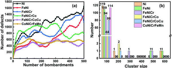
The defects are calculated using the centrosymmetry parameter method.44 In an ideal centrosymmetric material, each atom has a pair of equal and opposite bonds to its nearest neighbors. Although homogeneous elastic deformation will change the orientation or length of these bonds, each pair remains equal in size and opposite in orientation. However, when a defect is introduced into the material, each pair of bonds does not maintain equal size and opposite orientation. The centrosymmetry parameter is described as , where Si and Si+6 are the vectors or bonds corresponding to the six pairs of opposite nearest neighbors in the FCC lattice. For atoms in a perfectly centrosymmetric crystal or under homogeneous elastic deformation, the total contribution from the neighbors is zero. However, if defects exist in the materials, for the atoms in the region with defects, the value of V_CSP is non-zero. The numbers of defects in Ni, FeNi, CrFeNi, CoCrFeNi, CoCrCuFeNi and CoCrFeMnNi after 500 periods of bombardment are as shown as Fig. 2(a). The defects in pure Ni basically go up following the bombardment process. In the first 50 periods of bombardment, the number of defects increases rapidly in all six materials. Between 50 and 300 periods of bombardment, the defects in pure Ni still obviously increase; however, the defects in the other five alloys fluctuate, and the number of defects after 300 periods of bombardment does not differ much from the defects after 50 periods. The cause of the fluctuation is the annihilation of defects, which occurs when the interstitial atoms and vacancies meet during the movement of defects, leading to an obvious decrease in defects.
After 300 periods of bombardment, the number of defects in CrCoCuFeNi and CoCrFeMnNi HEAs is relatively stable at about 500. The number of defects in CoCrFeNi decreases significantly, but is still more than the defects in the two HEAs. The number of defects in pure Ni and FeNi rise rapidly. The number of defects in CrFeNi increases first, followed by a decrease at the end. At the end of the bombardment, the largest number of defects occurs in pure Ni, followed by FeNi, CrFeNi, CoCrFeNi, CoCrCuFeNi, and CoCrFeMnNi. The annihilation of defects in the two HEAs is relatively slight. However, there are multiple annihilation processes in the other four materials. The different behaviors can be attributed to the more complex elements in HEAs, which lead to lattice distortion and a hysteresis diffusion effect as other researchers have reported. Therefore, the movement of atoms and defects is suppressed, so fewer defects and annihilation processes occur.
Defect clusters of different sizes are generated during the bombardment process, as shown as Fig. 2b. Large clusters in which the number of defects is more than 200 occur in FeNi and CrFeNi. Small clusters dominate in the other materials, especially for the CoCrFeMnNi HEA, in which the defect clusters are all smaller than 100. In addition, the growth of defect clusters is different in the six materials, as shown as in Fig. S1 in the ESI.† Clusters where the number of defects is more than 100 occur in Ni, FeNi, CrFeNi and CoCrFeNi after 100 periods of bombardment. However, the growth of defect clusters in the two HEAs is relatively slow. The results show that the defects in the HEAs disperse and will be helpful for better irradiation resistance performance.
3.2 Dislocation
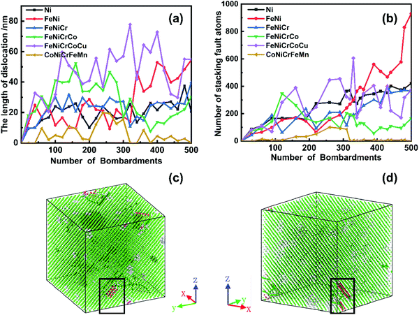
The OVITO DXA algorithm is used to measure the length of a dislocation. The results are shown in Fig. 3(a). The length of a dislocation fluctuates between 15 and 35 nm in pure Ni and CrFeNi, and remains relatively stable during the whole bombardment process. The fluctuation in FeNi and CoCrFeNi is larger than that in pure Ni or CrFeNi. The longest length of dislocation of about 80 nm is observed in CoCrCuFeNi. In contrast, the shortest length appears in the CoCrFeMnNi HEA. This phenomenon is different from the trends in defects in the two HEAs. In addition, the stacking faults generated by bombardment in the six materials are examined. As shown as in Fig. 3(b), the trend in the length of a dislocation is consistent with the number of stacking fault atoms. The stacking fault atoms generated during the bombardment of CoCrCuFeNi and CoCrFeMnNi HEA are shown in Fig. 3(c) and (d), in which the stacking fault atoms after 300 periods of bombardment in CoCrFeMnNi HEA are illustrated because they almost vanish after the entire bombardment process. The stacking faults in the other four materials are shown in Fig. S2 in the ESI.† The results show that the stacking faults occur after bombardment, and the dislocations are at the boundary of the stacking fault and FCC structures. A longer dislocation results in a larger number of stacking faults in CoCrCuFeNi, which implies that the slippage happens more easily in CoCrCuFeNi and might lead to better plasticity.To further validate the above speculation, the dislocation and atomic distribution of stacking faults during the whole bombardment in CoCrCuFeNi and CoCrFeMnNi are examined, as shown as in Fig. 4 and 5, respectively. The results of the other four materials can be found in Fig. S3 in the ESI.† As shown as in Fig. 4, during the irradiation process, multiple cascade collisions cause stacking faults in CoCrCuFeNi. A large number of dislocations are formed between the region including stacking faults and other regions, in which 1/6〈112〉 Shockley dislocations dominate. Most stacking fault atoms are in dislocation loops. However, the dislocations in CoCrFeMnNi are much fewer, and tend to self-heal during the bombardment process, as shown as in Fig. 5.
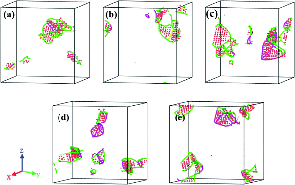 | ||
| Fig. 4 Dislocation and atomic distribution of stacking faults in CoCrCuFeNi HEA. The dots and lines have the same meaning as in Fig. 3. (a)–(e) are the cases after 100, 200, 300, 400, and 500 periods of bombardment, respectively. | ||
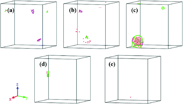 | ||
| Fig. 5 Dislocation and atomic distribution of stacking faults in CoCrFeMnNi HEA. The dots and lines have the same meaning as in Fig. 3. (a)–(e) are also the cases after 100, 200, 300, 400, and 500 periods of bombardment, respectively. | ||
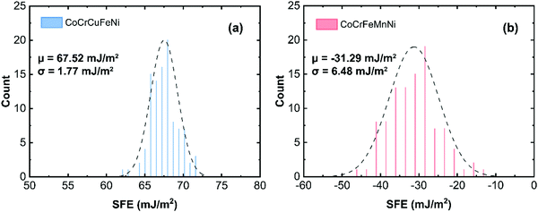
The difference in components between the two HEAs are the elements Cu and Mn. The stacking fault energies of CoCrCuFeNi and CoCrFeMnNi were calculated, as shown in Fig. 6, and are 67.52 mJ m−2 and −31.29 mJ m−2, respectively. Zhao et al.45 investigated the stacking fault energies of a series of multiple alloys using first principles theory and indicated that the presentation of negative stacking fault energies in multiple alloys was important for vibrational entropy in stabilizing their FCC structures. In our results, the negative stacking fault in CoCrFeMnNi suggests that the FCC structure of CoCrFeMnNi is more stable; therefore, few dislocations or stacking faults occur.
4. Conclusions
We have investigated the effect of chemical complexity on the irradiation resistance of alloys by means of molecular dynamics simulations. The irradiation resistance of six FCC structures, Ni, FeNi, CrFeNi, CoCrFeNi, CoCrCuFeNi and CoCrFeMnNi, was scrutinized. Consecutive bombardments cause defects in the materials, and the defects decrease with an increase in the number of components in the alloys. The multicomponent alloys, including CoCrCuFeNi and CoCrFeMnNi, in general have much fewer defects than single-element crystals. Multicomponent alloys also show better performance in irradiation resistance than single-element crystals. The growth of defects is slower in HEAs than in alloys with a smaller number of alloying elements, which indicates that defect clusters decrease with respect to the increase in the complexity of elements. There are fewer than 100 defect clusters in the two HEAs after 500 periods of bombardment. However, large defect clusters are observed in Ni, FeNi, CrFeNi, CoCrFeNi, which indicates less diffusion of defects in HEAs.The longest and shortest dislocation lengths are observed in CoCrCuFeNi and CoCrFeMnNi, respectively, which show different trends in defects. A longer length of dislocation in an alloy leads to a large amount of stacking faults in CoCrCuFeNi. The lower number of defects and dislocations indicates that the CoCrFeMnNi high entropy alloy has excellent irradiation resistance. Our atomistic insights into the effect of chemical complexity on irradiation resistance might be helpful in the design of structural materials for next-generation nuclear reactors.
Author contributions
Lingyun Qian and Honggang Bao carried out the simulation and wrote the manuscript. Rui Li guided the study, took part in the analysis and revised the manuscript. Qing Peng took part in analysis and revised the manuscript.Conflicts of interest
There are no conflicts to declare.Acknowledgements
The work is supported by Fundamental Research funds for the Central Universities (FRF-IDRY-20-008 and FRF-AT-20-09). Q. Peng would like to acknowledge the support provided by LiYing Program of the Institute of Mechanics, Chinese Academy of Sciences (E1Z1011001).References
- R. J. Budnitz, Energy Policy, 2016, 96, 735–739 CrossRef.
- S. J. Zinkle, Phys. Plasmas, 2005, 12(5), 058101 CrossRef.
- Q. Peng, F. Meng, Y. Yang, C. Lu, H. Deng, L. Wang, S. De and F. Gao, Shockwave generates 〈100〉 dislocation loops in bcc iron, Nat. Commun., 2018, 9(1), 1–6 CrossRef.
- P. Yvon and F. Carré, J. Nucl. Mater., 2009, 385(2), 217–222 CrossRef CAS.
- I. Charit and K. L. Murty, JOM, 2010, 62(9), 67–74 CrossRef.
- K. Nordlund, M. Ghaly, R. S. Averback, M. Caturla and J. Tarus, Phys. Rev. B: Condens. Matter Mater. Phys., 1998, 57(13), 7556–7570 CrossRef CAS.
- S. J. Zinkle and G. Was, Acta Mater., 2013, 61(3), 735–758 CrossRef CAS.
- S. J. Zinkle and L. L. Snead, Annu. Rev. Mater. Res., 2014, 44, 241–267 CrossRef CAS.
- Y. Ye, Q. Wang, J. Lu, C. Liu and Y. Yang, Mater. Today, 2016, 19(6), 349–362 CrossRef CAS.
- D. B. Miracle and O. N. Senkov, Acta Mater., 2017, 122, 448–511 CrossRef CAS.
- Y. Lu, Y. Dong, S. Guo, L. Jiang, H. Kang and T. Wang, et al., A promising new class of high-temperature alloys: eutectic high-entropy alloys, Sci. Rep., 2014, 4, 6200 CrossRef CAS.
- Y. Lu, Y. Dong, S. Guo, L. Jiang, H. Kang, T. Wang, B. Wen, Z. Wang, J. Jie and Z. Cao, Adv. Eng. Mater., 2004, 6(5), 299–303 CrossRef.
- Z. Wu, H. Bei, G. M. Pharr and E. P. George, Acta Mater., 2014, 81, 428–441 CrossRef CAS.
- M.-H. Tsai, Entropy, 2013, 15(12), 5338–5345 CrossRef CAS.
- Z. Li, K. G. Pradeep, Y. Deng, D. Raabe and C. C. Tasan, Nature, 2016, 534(7606), 227–230 CrossRef CAS PubMed.
- B. Zhang, Y. Zhang and S. M. Guo, J. Mater. Sci., 2018, 53(20), 14729–14738 CrossRef CAS.
- R. K. Mishra, P. P. Sahay and R. R. Shahi, J. Mater. Sci., 2019, 54(5), 4433–4443 CrossRef CAS.
- B. Gludovatz, A. Hohenwarter, K. V. Thurston, H. Bei, Z. Wu, E. P. George and R. O. Ritchie, Nat. Commun., 2016, 7(1), 1–8 Search PubMed.
- Z. Wu, Y. Gao and H. Bei, Scr. Mater., 2015, 109, 108–112 CrossRef CAS.
- G. Buluc, R. Chelariu, G. Popescu, M. Sârghi and I. Carcea, Key Eng. Mater., 2017, 4568, 34–38 Search PubMed.
- Q. Ye, K. Feng, Z. Li, F. Lu, R. Li, J. Huang and Y. Wu, Appl. Surf. Sci., 2017, 396, 1420–1426 CrossRef CAS.
- Z. Chen, W. Chen, B. Wu, X. Cao, L. Liu and Z. Fu, Mater. Sci. Eng., A, 2015, 648, 217–224 CrossRef CAS.
- S. Zhao, Y. Zhang and W. J. Weber, Scr. Mater., 2018, 145, 71–75 CrossRef CAS.
- X. Wang, C. M. Barr, K. Jin, H. Bei, K. Hattar, W. J. Weber, Y. Zhang and K. L. More, J. Nucl. Mater., 2019, 523, 502–509 CrossRef CAS.
- J.-W. Yeh, JOM, 2015, 67(10), 2254–2261 CrossRef CAS.
- Z. Wang, Q. Fang, J. Li, B. Liu and Y. Liu, J. Mater. Sci. Technol., 2018, 34(2), 349–354 CrossRef CAS.
- M. Vaidya, S. Trubel, B. Murty, G. Wilde and S. V. Divinski, J. Alloys Compd., 2016, 688, 994–1001 CrossRef CAS.
- K.-Y. Tsai, M.-H. Tsai and J.-W. Yeh, Acta Mater., 2013, 61(13), 4887–4897 CrossRef CAS.
- Y. Wang, K. Zhang, Y. Feng, Y. Li, W. Tang and B. Wei, Entropy, 2018, 20(11), 835 CrossRef CAS.
- N. A. P. K. Kumar, C. Li, K. J. Leonard, H. Bei and S. J. Zinkle, Acta Mater., 2016, 113, 230–244 CrossRef CAS.
- H.-S. Do and B.-J. Lee, Sci. Rep., 2018, 8(1), 16015 CrossRef PubMed.
- C. Lu, L. Niu, N. Chen, K. Jin, T. Yang, P. Xiu, Y. Zhang, F. Gao, H. Bei, S. Shi, M.-R. He, I. M. Robertson, W. J. Weber and L. Wang, Nat. Commun., 2016, 7(1), 49–51 Search PubMed.
- Y. Li, R. Li and Q. Peng, Nanotechnology, 2019, 31(2), 025703 CrossRef PubMed.
- S. Xia, Z. Wang, T. Yang and Y. Zhang, J. Iron Steel Res. Int., 2015, 22(10), 879–884 CrossRef.
- E. Levo, F. Granberg, C. Fridlund, K. Nordlund and F. Djurabekova, J. Nucl. Mater., 2017, 490, 323–332 CrossRef CAS.
- F. Granberg, K. Nordlund, M. W. Ullah, K. Jin, C. Lu, H. Bei, L. Wang, F. Djurabekova, W. Weber and Y. Zhang, Phys. Rev. Lett., 2016, 116(13), 135504 CrossRef CAS PubMed.
- D. Farkas and A. Caro, J. Mater. Res., 2018, 33(19), 3218–3225 CrossRef CAS.
- J. Biersack and J. Ziegler, Ion Implant. Sci. Technol., 1984, 1(1), 51–108 Search PubMed.
- W.-M. Choi, Y. H. Jo, S. S. Sohn, S. Lee and B.-J. Lee, npj Comput. Mater., 2018, 4(1), 1–9 CrossRef CAS.
- S. Plimpton, J. Comput. Phys., 1995, 117(1), 1–19 CrossRef CAS.
- A. Lemak and N. Balabaev, Mol. Simul., 1994, 13(3), 177–187 CrossRef CAS.
- H. Huang, X. Tang, F. Chen, J. Liu and D. Chen, J. Nucl. Mater., 2017, 493, 322–329 CrossRef CAS.
- A. Stukowski, Modell. Simul. Mater. Sci. Eng., 2009, 18(1), 015012 CrossRef.
- C. L. Kelchner, S. Plimpton and J. Hamilton, Phys. Rev. B: Condens. Matter Mater. Phys., 1998, 58(17), 11085 CrossRef CAS.
- S. Zhao, G. M. Stocks and Y. Zhang, Acta Mater., 2017, 134, 334–345 CrossRef CAS.
Footnote |
| † Electronic supplementary information (ESI) available. See DOI: 10.1039/d1ma01184g |
| This journal is © The Royal Society of Chemistry 2022 |

