 Open Access Article
A biodegradable silver oxide-treated hydroxyapatite nanoparticle (AgO@HA)-interlaced poly(etherimide)/poly(methylmethacrylate) membrane for blood purification: an in vitro study†
Selvam
Sivasankari
a,
Rajappan
Kalaivizhi
 *a,
Munuswamy Ramanujam
Ganesh
a and
Musthafa Shazia
Anjum
b
aDepartment of Chemistry, SRM Institute of Science and Technology, Kattankulathur, Tamil Nadu, India. E-mail: Kalaivir@srmist.edu.in
bDepartment of Biotechnology, SRM Institute of Science and Technology, Kattankulathur, Tamil Nadu, India
First published on 14th April 2022
Abstract
The growing prevalence of renal disorder and the scarcity of healthy kidneys for donation necessitate the research and development of new types of hemodialysis membrane. By incorporating silver oxide-doped hydroxyapatite (AgO@HA) nanoparticles (NPs) into polyetherimide (PEI)/polymethylmethacrylate (PMMA) mixed matrix membranes (MMMs), we would like to develop a hemodialysis membrane that is more productive and biocompatible. The effective incorporation of hydrophilic AgO@HA on PEI/PMMA membrane surfaces was confirmed through analyses of X-ray diffraction (XRD) and Fourier transform-infrared spectroscopy (FT-IR). The AgO@HA integrated PEI/PMMA matrix membrane enhanced the hydrophilicity, as evaluated by water contact angle (CA), water uptake ratio (WU), and swelling ratio (SR). AgO@HA had a greater bioavailability; hence these MMMs were considerably more biocompatible with blood and cells. They had a higher resistance to blood coagulation, hemodialysis assay and plasma recalcification time, and a longer clotting time. Then, the biocompatibility was analyzed by the cell viability and Acridine orange/ethidium bromide (AO/EtBr) technique. In addition, to determine the degradable percentage of the nanocomposite membrane, a biodegradability test was carried out using soil burial methods. All of these findings suggest that the AgO@HA-PEI/PMMA MMMs should be investigated further for use in blood-purifying applications.
1. Introduction
Effective membrane filtration is a widely used technology in a variety of chemical processes, including desalination, protein separation and purification, and hemodialysis. Biological membranes enable living systems to function in nature without succumbing to entropically driven chaos. As a consequence, scaling up the fabrication of biologically generated membranes for the separation of a wide range of chemicals and particles has proven challenging, prompting researchers and the membrane industry to turn to artificial materials.1 Hemodialysis, as one of the most efficient medical therapies for the treatment of kidney function disorders, requires rigorous materials. Thrombosis, red blood cells, and platelets, among other things, will stick to materials with low hemocompatibility. The hemodialysis membrane is at the core of the dialyzer, and its high hemocompatibility can minimize the chances of thrombosis during dialysis. However, the hydrophobicity and low hemocompatibility of polymer membranes prevent them from being a good hemodialysis membrane choice. Fouling is a key issue with all membranes having hydrophobicity in commercial processes.2Anti-fouling components have notable medicinal benefits as blood-compatible devices, which are particularly inspiring in the design of hemodialysis membranes, antithrombogenic implants, and biosensors that come into contact with human blood.3 As a result, people with kidney disease must undergo hemodialysis, a necessary medical procedure that uses a porous material to remove toxic substances from human plasma. Small molecules including urea, creatinine, and lysozyme, as well as excess water and physical saline, should be isolated.4–6 Toxins such as urea, uric acid, excess glucose, and creatinine, among others, are discharged from the blood to the dialysis fluid side during hemodialysis, while essential proteins are prevented from leaving the bloodstream. All of this is facilitated by a polymeric membrane that allows the metabolic waste from the bloodstream to pass to the dialysate side, while rejecting proteins in the bloodstream. When blood flow comes in direct contact with a membrane, it exhibits non-Newtonian characteristics, which impacts the filtration or separation process.7–9
As a result, improved biocompatibility, particularly anticoagulant filter membrane capabilities, is essential for extending membrane life and lowering clinical services.10 Kidney dialysis films such as polyvinylidene fluoride, polymethylmethacrylate, polyethersulfone, polysulfone, polyetherimide, and cellulose are being used in clinical treatments due to their higher clearance efficiency. These membranes, however, are not optimal because of their anticoagulant and fouling effects. Although dialysis patients must go about their regular lifestyle properly, the bulk of hemodialysis membranes are manufactured for hospital use. Non-solvent phase separation (NPS) is used in the majority of membrane production technology. Initially, a polymer is dissolved in a suitable solvent, usually as part of an additive. It has been demonstrated that adding inorganic nutrients like lithium chloride (LiCl) or polymers like PEG and PVP to the membrane promotes penetration and durability. Afterwards, the polymer solution is poured on a flat frame or produced as a hollow fiber and submerged in a non-solvent, where it splits into two phases: a polymer-rich phase that cures into the membrane structure and a polymer-poor phase that is washed away, creating the pores. Because water does not dissolve commonly used polymers, is affordable, and is convenient on a massive scale, it is widely employed as a non-solvent. The very next steps are membrane rinsing and module preparation. During coagulation and rinsing, the polymer-lean phase (mainly solvent and additive) is washed with water and reused or discharged into the drainage systems.11
A unique feature of adsorption is found in polymethylmethacrylate membranes (PMMA), which can remove molecular compounds medium and high in weight, which cannot be eliminated through standard hemodialysis and hemodiafiltration. The newly developed PMMA membrane removes platelet adherence on the membrane surface and maintains adsorption characteristics. In patients with hemodialysis, Nano filtration(NF) membrane in comparison to regular PMMA membranes is essential to raise inflammatory conditions and clinical complaints.12 To date polyimide materials such as polyetherimide (PEI) have not been employed extensively as biomaterials. Polyimides that allow cell tissues to be connected and formed have just been discovered to be safe of cytotoxic effects and hemolysis in the latest biomedical application investigations. PEI is therefore expected to be a biomedical applicant for portions of intraocular lenses, biosensors, oxygenators or neuro-prostheses. It is also expected, as proved recently, that PEI is also extremely mechanically and thermally stable.13 PEI can be incorporated into membranes and employed as a legend through a variety of chemical alterations. Under this investigation, we established a blending solution that incorporates the features of PMMA in membrane creation, such as pore size distribution homogeneity and tensile stability, with the characteristics of PEI, also including bioactivity and the capacity to efficiently capture biomolecules (protein).14,15
Bioinspired synthetically produced hydroxyapatite nanoparticles (NPs) (Ca10(PO4)6(OH)2, HA) have been widely used in orthopaedic biomedical applications, including implant coatings, bone fillers, bone cements, drug and gene delivery systems, as a scaffold for bone tissue engineering, and even wound healing dressings. An optimal orthopaedic implant should be able to decrease biofilm development and attachment, while also promoting the desired biocompatibility.16–18 Despite its high biocompatibility, bioactivity, and osteoconductivity, HA lacks inherent antimicrobial properties. To address this issue, synthetic HAs doped with various ions have been developed in an attempt to introduce antimicrobial properties, while also enhancing osteoconductivity. Ion-doped HAs with Ag+, Cu2+, and Zn2+ ions have been developed, with the Ag-doped HA (Ag–HA) synthesized at alkaline pH providing the most considerable antibacterial properties. Considerably, bacterial cells find it difficult to develop silver resistance. Silver has been used as an antimicrobial agent for centuries due to these benefits, and it is broadly used in catheters and wound healing dressings. The Ag–HA NPs could be used effectively as bone fillers or as implant surface coatings. The cytotoxicity of such Ag–HA NPs, however, has not previously been investigated.19–22
Moreover, the first event that occurs when a surface is introduced into biological fluid is the adsorption of a surface membrane. This adsorbed coating of proteins is “seen” by the host cells. The contact between proteins and the interface might alter the shape of adsorbed proteins, revealing new epitopes and resulting in cellular responses that differ from the standard. To get insight into how cells will respond, it is vital to understand the interaction between the surface of implants and proteins. The inclusion of Ag+ in Ag–HA NPs may have a different effect on protein adsorption and conformation than Ca2+ in HA, but this impact needs to be investigated further.23–27
In this research, we propose that silver oxide-doped hydroxyapatite-intermixed poly(etherimide)/poly(methylmethacrylate) increases the hydrophilicity and hemocompatibility performance of the membrane. With chemical procedures, different quantities of AgO@HA are mixed with PEI/PMMA to produce hydrophilic hemocompatible membranes after the blending of PMMA and AgO@HA. To learn more about the potential of membranes to foul in a poor electric field, we devised an electric field-assisted apparatus. X-Ray diffraction (XRD), Fourier transform-infrared spectroscopy (FT-IR), and scanning electron microscopy (SEM) are used to determine the structure and functioning of the membranes. Blood coagulation, hemodialysis assay, plasma recalcification time, and a longer clotting time were used to assess the hemocompatibility of the developed MMMs. The biocompatibility was then examined using the cell-viability and AO/EtBr techniques. A soil burial test has been used to conduct the biodegradability evaluations.
2. Experimental methods
2.1. Synthesis of silver-doped hydroxyapatite nanoparticles (AgO@HA NPs)
Ca (NO3)2·4H2O and (NH4)2HPO4 were used for chemical precipitation to synthesise the hydroxyapatite (Ca10−xAgx(PO4)6(OH)2) ceramic powder (Ca/P molar ratio: 1.67). The ratio [Ca+Ag]/P of the silver-doped hydroxyapatite nanoparticles was 1.67. To make a 300 mL [Ca+Ag]− containing solution, AgNO3 and Ca (NO3)2·4H2O were dissolved in deionized water. (NH4)2HPO4 was dissolved in deionized water to make a solution with a final volume of 300 mL. For 30 min, the [Ca+Ag]− containing solution was agitated at 100 °C. Drop by drop, the P-containing solution was added to the [Ca+Ag]−-containing solution with a pH of 10 (adjusted by NH3) and agitated for 2 h. Throughout the reaction, the pH was maintained at 10. After that, the precipitate was rinsed with deionized water numerous times. The obtained material was dried for 12 hours at 100 °C (Fig. 1(a)).28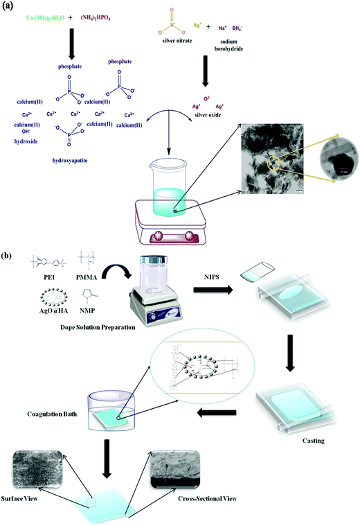 | ||
| Fig. 1 Schematic representation of (a) synthesis of AgO@HA nanoparticles, and (b) AgO@HA-incorporated PEI-PMMA polymer-mixed matrix membrane preparation via the phase inversion method. | ||
2.2. Preparation of a mixed matrix membrane
Fig. 1(b) illustrates the schematic representation of the phase inversion approach to prepare the mixed matrix membranes. Doping solutions were made by dissolving polymers (PEI and PMMA) and the nanocomposite in various compositions (Table 1) in NMP as the solvent. The solution was homogenized for 4 h at 40 °C with continual mechanical stirring. After that, the homogeneous solution was cast on a glass plate to a consistent thickness. The cast film on the glass plate was immediately placed in a gelation bath that included distilled water, 2% NMP (solvent), and 0.2% SLS (surfactant) (non-solvent). During the casting and gelation processes, strict conditions were maintained to ensure that membranes with better physical qualities such as homogeneity, thickness, and morphology were created. After the casting was completed, the cast film was allowed to dry before being gently immersed in the gelation bath for 1 h with the glass plate. To remove the surfactant and solvent, the developed membrane was thoroughly rinsed with distilled water and properly stored until further testing.29,30| Membrane identification | Polymer blend composition (17.5 wt%) | Solvent (wt%) | Nanoparticles | (wt%) |
|---|---|---|---|---|
| PEI | PMMA | NMP | AgO@HA | |
| M1 | 100 | 0 | 75.5 | 0 |
| M2 | 0 | 100 | 75.5 | 0 |
| M3 | 90 | 10 | 75.5 | 0 |
| M4 | 80 | 20 | 75.5 | 0.05 |
| M5 | 70 | 30 | 75.5 | 1.5 |
3. Results and discussion
3.1. Characterization of the mixed matrix membrane
The XRD patterns of the AgO@HA NPs and AgO@HA-doped polymer membrane are depicted in Fig. 2(a). The XRD pattern of the AgO@HA NPs corresponds to the (002), (012), (121), (030), (222), (123) and (004) diffraction planes, respectively. HA's Bragg's reflection angles were very similar to those earlier reported (JCPDS No. 00-09-0432). Two extra Bragg's reflection peaks were found in AgOHA, confirming the existence of metallic silver (JCPDS No. 01-087-0720).31,32 The XRD analysis for the ultrafine PEI/PMMA polymer membrane revealed PEI diffraction planes at (001), (100), (002), (110), (003), (210), and (300), and (111), (002), (112) and (211) diffraction planes corresponding to the PMMA polymer.33 The XRD analysis for the ultrafine PEI/PMMA polymer membrane revealed no strong diffraction lines, confirming the polymer's non-crystalline structure. The XRD analysis was used to indicate the existence of the material in the membrane by evaluating the diffraction of the material under test. The resulting diffraction pattern, which includes both the positions and intensities of the diffraction effects, can be used not only for rapid identification, but also for complete elucidation of its structure.34,35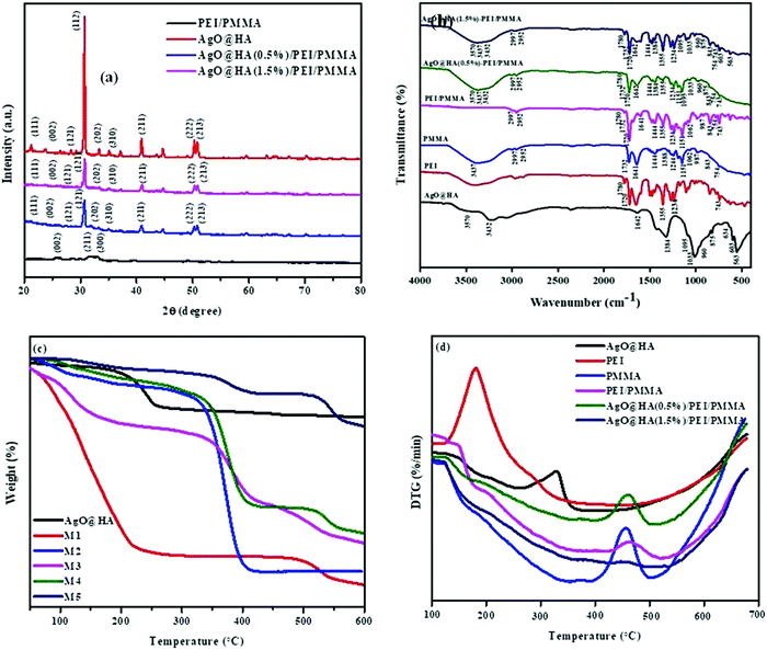 | ||
| Fig. 2 Images of (a) XRD spectra, (b) FT-IR spectra, (c) thermogravimetric analysis (TGA), and (d) differential thermal analysis (DTA) spectra of AgO@HA nanoparticles, and mixed matrix membranes. | ||
The FT-IR spectra of the AgO@HA nanoparticles and PEI/PMMA polymer membrane with two different molar ratios of HA to Ag+ are shown in Fig. 2(b). FT-IR was used to identify the functional groups present in the prepared AgOHA powder by the wet chemical precipitation method. The obtained results clearly show the presence of various vibrational modes that correspond to hydroxyl groups and phosphates. The spectra can be divided into four major regions, with wave numbers ranging from 3500 cm-1 to 1400 cm-1 and 600 cm-1 for the peaks. The spectra revealed the presence of a strong OH peak. The presence of an –OH bond is responsible for the peak at 3425 cm-1. The O–H stretching vibrations in HA cause this peak. The bands seen at 1600–1700 cm-1 and 3200–33600 cm-1 are caused by H–O–H bands in the water lattice. Bands in the spectra corresponding to phosphate and hydrogen phosphate groups include those at 565.16 cm-1, 603.74 cm-1, 632.67 cm-1, 962.51 cm-1, and 1000–1100 cm-1 for the PO43− groups and 875.71 cm-1 for the HPO42− ions. Thus, the presence of the PO43− group is confirmed by IR studies. The FT-IR spectra of AgO@HA are generally compatible with those shown in Fig. 2(b), confirming that the configuration of surface chemical bonding for AgO NP-loaded HA nanoparticles has remained remarkably stable. However, the bands’ frequencies appear to be red-shifted to lower wave numbers, specifically for the bands centered at 1050 cm-1. This could be owing to AgO NPs interacting with the hydroxyl or PO43− groups in the HA.36 Many peaks in the FT-IR spectra of pure PEI fibers are attributed to the presence of C 14O, C–N, C–N–C, and C–O bonds. At 1717 cm-1, the characteristic imide bands (symmetric and asymmetric stretching, respectively) can be observed. At 1357 cm-1, the imide ring's C–N–C absorption was found. At 1236 cm-1, the C–O stretching appears, and at 743 cm-1, the C–N stretching appears.37 Near 2840–2950 cm-1, the stretching vibration of the CH2 group emerged. The stretching vibration of the C![[double bond, length as m-dash]](https://www.rsc.org/images/entities/char_e001.gif) O group appeared at 1730 cm-1, the stretching vibrations of the C–O groups appeared at 1240 and 1148 cm-1, and the absorption peak of the C
O group appeared at 1730 cm-1, the stretching vibrations of the C–O groups appeared at 1240 and 1148 cm-1, and the absorption peak of the C![[double bond, length as m-dash]](https://www.rsc.org/images/entities/char_e001.gif) C group vanished. This demonstrates that the MMM monomers are blended.38
C group vanished. This demonstrates that the MMM monomers are blended.38
Thermal behavior is shown in Fig. 2. Generally, thermal stability is critical in determining the optimal temperature range for the thin film to be effective. The thin film was then subjected to a thermo gravimetric examination that ranged from ambient temperature to 600 °C. TGA was used to quantify the purity of the silver oxide nanoparticle-doped scale sample (CaPO4) and decomposition of the polymer membranes. According to these data, three distinct weight loss slopes can be seen at temperatures of 99, 200, and 445 °C. The graph indicates OH groupings around 200 °C. Carbon levels included in nanoparticles were assigned to a temperature of 445 °C, below 200 °C in biomass. The sample includes metal surface-desorbed bio-organic material (4.10%), according to TGA. The bio-impurities in the sample are minimal. Nanoparticles can use impurities as nucleation sites and capping agents, because biomass contains a considerable amount of scale salts.39 The thermogram (TG) curves of several polymer membranes are presented in Fig. 2(c). These membranes have two stages of heat disintegration, as can be seen. The first stage of deterioration appeared at 100 °C due to evaporation of water and residual solvent, and only slight weight loss was detected until 200 °C. Pure PEI membranes exhibited the most notable thermal deterioration behavior around 450 °C, which was attributed to PEI main chain degradation. Furthermore, the addition of NPs accelerated the thermal stability of the composite membranes at high temperatures, as can be seen in the differential thermogram (DTG) curves in Fig. 2(d). The TGA curves show a steady decrease in degradation. In this investigation, polyetherimide displays good thermal stability, with no massive weight loss up to 430 °C in air. When the temperature reaches 450 °C, the weight loss is 20%. At a temperature of 800 °C, about half of the char production was produced. The very first stage of decomposition for PEI appeared at 410 °C, and the second stage occurred between 400 and 800 °C. PEI has the highest thermal stability and the least weight loss of all the membranes synthesized, which could be attributed to the presence of metal oxide. PEI is clearly an amorphous thermoplastic, as evidenced by the TGA results.40–42 The pure PMMA membrane, on the other hand, was shown to have a higher thermal degradation temperature than the composite PEI/PMMA membranes of various compositions. According to three distinct weight losses, pure PMMA appears to degrade. Different modes of depolymerization start have been attributed to these stages. The breakage of weak head-to-head links in the main chain causes the first (about 300 °C), terminal vinyl group breakdown causes the second (around 350 °C), and random bond cleavage of the polymer main chain promotes the third (around 370 °C). TG curves revealed the endpoint of degradation at around 550 °C. The DTA curve of AgO@HA (0.5%)-PEI/PMMA compared with that of the pure PMMA exhibits no changes in the degradation process, but the presence of a higher weight percentage of AgO@HA shows the good thermal stability for the AgO@HA(1.5%)-PEI/PMMA membrane. The lower thermal degradation temperatures seen in AgO@HA-PEI/PMMA blend membranes could be attributed to the insertion of AgO@HA into the PEI/PMMA polymer matrix, which has a degradation temperature of just 355 °C.43,44
3.2. Morphological analysis
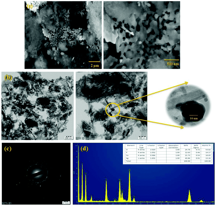
The morphological examination of the produced composite AgO@HA material is shown in Fig. 3. The AgO@HA nanoparticle morphology shows silver nanoparticles, which were deposited by homogeneous nucleation and growth on the surface of the hydroxyapatite nano-rods. The average length and diameter of the AgO@HA nanoparticles were determined to be 5–6 μm in Fig. 3(a) from HR-SEM images. The HR-TEM pictures of the AgO@HA nanoparticles are shown in Fig. 3(b). From the related XRD pattern, we demonstrate that there is no other binary compound besides AgO@HA nanoparticles. The average diameter of the silver oxide nanoparticles increased from 5 nm to 14 nm, and the length of the HA nano-rods was reduced from 9 nm to 3 nm. Fig. 3(c) reveals the SAED micrograph of various HA NPs. The SAED pattern of the unique AgO@HA NPs shows distinguishable diffraction rings that correspond to the crystallographic planes (002) and (211).45 The energy dispersive X-ray analysis (EDAX) of composite nanoparticles that include calcium, phosphate, silver, and oxygen is represented in Fig. 3(d). According to the weight percentage table, the atomic ratio of Ag and HA is 1![[thin space (1/6-em)]](https://www.rsc.org/images/entities/char_2009.gif) :
:![[thin space (1/6-em)]](https://www.rsc.org/images/entities/char_2009.gif) 2.46–48
2.46–48
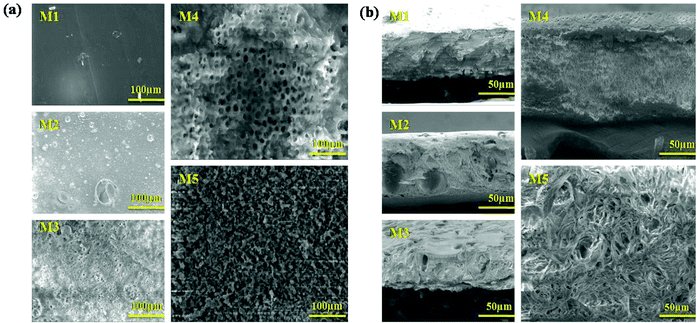
The surface topography of the polymer membranes is identified via an HR-SEM investigation. Fig. 4(a and b) exhibit the top and cross-sectional images of the PEI (M1) PMMA (M2), PEI/PMMA (M3), AgO@HA(0.5%)-PEI/PMMA (M4) and AgO@HA(1.5%)-PEI/PMMA (M5) nanocomposite membranes. PEI membranes have low pore formation ability, which is confirmed by the non-porous morphology in both surface and cross-sectional view, compared to the literature. The M4 and M5 membranes indicate the existence of porous, transparent vacuum structures. The cross-sectional pictures of the membrane clearly show the expansion in the pores and improvements of the finger like structures in a way that is porous. The PEI/PMMA polymer membrane combined nanocomposites interact strongly with the solvent and with non-solvent, which makes the membrane layers dense. There was therefore good hydrophilicity of the custom PEI/PMMA membrane containing nanocomposites. In contrast, the membrane containing 1.5% of AgO@HA nanoparticles showed maximal holes and the configuration of a micro-void with higher hydrophilicity.49,50
The porosities and mean pore size distribution of all of the designed membranes have been examined, and the results are reported in Table 2. The porosities of the blend membranes have been found to be significantly higher than that of the pristine PEI membrane. The pristine membrane just has a porosity of 34.20%. The porosity of the 70/30 PEI/PMMA membrane composite increased with the NPs showing the porosity of 52.89%; on the other hand, increasing the dosage of AgO@HA NPs extended the maximum porosity value to around 60.98%. Both studies have found that the hydrophilic nature and characteristics of the constituent polymers in the blend and the membrane pore size, strongly influence the flux. As the proportion of AgO@HA was increased, the pores and mean pore diameter of the membranes increased, which correlated with the SEM data. The pristine M1 and M2 had pore sizes of 2.21 μm and 2.82 μm; however the membrane M3 had a pore size of 3.12 μm. The existence of AgO@HA nanoparticles in the polymer solutions influenced the micro phase separations, which assisted in the creation of a polymer-poor phase, suggesting that AgO@HA nanoparticles are suitable for membranes with a porous structure and the average pore size of M4 is 3.92 μm and that of M5 is 4.16 μm.51,52
| Membrane identification | Porosity, ε (%) | Mean pore size, rm (μm) |
|---|---|---|
| M1 | 34.20 | 2.21 |
| M2 | 30.20 | 2.82 |
| M3 | 44.63 | 3.12 |
| M4 | 52.89 | 3.92 |
| M5 | 60.98 | 4.16 |
3.3. Water intake analysis
The contact angle measurement reveals the attraction of a solid surface to facing liquids. As a result, contact angle observation is used to explore the hydrophilicity and chemical modifications on the membrane's surface. Following the contact angle measurement operating conditions, the micro syringe drops 3.5 micro liters of water on the surface of the membrane, and the water drops distributed out quickly on the membrane surface. The hydrophilic nature of the AgO@HA-incorporated PEI/PMMA mixed matrix membrane (70.8°) is evaluated by comparison to that of a plain PEI/PMMA membrane (77.4°) and other membranes, as shown in Fig. 5(a). Nevertheless, since the wettability of the membrane is governed by surface roughness and porosity, these parameters can be met by embedding nanoparticles. High-porosity membranes have lower contact angles and are more hydrophilic in nature for the same reason.53–55 The adsorption capacity and porous nature of the membrane determine the water uptake ratio (WU). The water uptake ratio and swelling ratio percentage were used to evaluate the hydrophilicity of the membrane. Adsorption efficiency is largely defined by the van der Waals interaction of water molecules with the functional groups on the membrane surface. Fig. 5(b) portrays the water uptake and swelling ratios for M1–M5. The plain poly(methylmethacrylate) membrane (M2) has a lower water uptake ratio than the other membranes. The inclusion of PEI in the PMMA in M3 results in higher water uptake ratio due to the hydrophilic nature of the membrane. Conversely, the composition of the nanoparticles in the polymer membrane that encourages the water intake depends resonantly on M4 and M5. A steady increase and swelling is reduced with the M1–M5 percentage of water consumption. Membranes M4 and M5 illustrate good hydrophilic uptake ratios that could be caused by adding nanoparticles as pore creators to expand the pores in order to absorb the membrane composite well. The increase in the membrane hydrophilicity is protected from the swelling ratio.56,57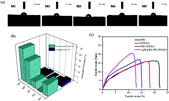 | ||
| Fig. 5 Images of (a) contact angle measurement, (b) water uptake (WU) ratio and swelling ratio (SW) and (c) tensile strength of the mixed matrix membranes. | ||
3.4. Mechanical properties
The observable mechanical characteristics of the manufactured pristine PEI membrane have been measured using uniaxial tensile tests. The integration of nanomaterials into the membrane architecture is estimated to have an impact on the polymer membrane mechanical behavior. As a consequence, uniaxial tensile tests were performed in accordance with the specific requirements as outlined. The mechanical properties of the PEI nanocomposites have been evaluated to ensure their suitability for the biomedical field. Hydrated membranes exhibit mechanically worse behavior than the dry membranes at the same temperature and relative humidity. Hydrated membranes swell, the intermolecular gap expands, and the interaction force weakens after water uptake, resulting in reduced mechanical stability. Table 3 presents the % actual stress (σ)-strain (ε) curves for virgin PEI and nano-modified membranes, respectively. For each framework type, the estimated Young's modulus (E), tensile strength (σmax), and strain at break percent (εmax, %) values were determined. All construction types had a series of successive behaviors. Positive outcomes were seen in the PEI and PEI nanocomposite scaffolds have been generated and tested under the same parameters. Table 3 shows the overall values of evident E, σmax, and εmax (%), values.58,59| Membrane identification | Membrane thickness (μm) | Tensile strength (Mpa) | Elongation at break(%) | Young's modulus (Mpa) |
|---|---|---|---|---|
| M1 | 1.5 | 15.791 | 21.460 | 0.783 ± 4.221 |
| M2 | 1.1 | 16.029 | 17.493 | 0.089 ± 3.051 |
| M3 | 1.4 | 17.217 | 14.344 | 1.032 ± 4.267 |
| M4 | 1.8 | 20.639 | 11.574 | 1.8962 ± 3.45 |
| M5 | 1.9 | 20.893 | 11.647 | 1.9986 ± 3.96 |
The addition of AgO@HA NPs had no significant influence on the maximum value of the PEI frameworks, which indicated a slight decrease of 2.4% (from 0.783 ± 4.221 MPa to 1.8962 ± 3.45 MPa) but is out of consequence, according to experimental observations provided in Fig. 5(c). The tensile strength (E) value on the other hand increased by 70% (15.794 MPa to 20.893 MPa). This activity discloses the weak stimulating effect of NPs with the network polymer material (PEI), which can be believed to be due to the lack of free hydroxyl groups in the PEI chemical structure, which resulted in poor bonding among PEI and NPs (hydroxyl groups would support the creation of chemical bonds between PEI and AgO@HA NPs), and the PEI of the scaffolds.60,61 AgO@HA samples, on the other side, exhibited entirely different behavior, with dramatically enhanced mechanical behavior and the optimum mechanical performance. These actions indicate that excellent adhesion here between the PEI polymer and the AgO@HA and the fine distribution and the lack of agglomerations within the fibrous structure have been achieved. The results also demonstrate the successfulness and reliability of the nanoparticles and concentration rates utilized.62 In spite of the fact that NPs are usually stiffer, it was established that scaffolds incorporating AgO@HA NPs had superior mechanical performance based on the above-mentioned results for pristine membranes. As a result, it is evident that in a hybrid system, the polymer's adhesion to the reinforcement has a huge effect on the material's ultimate mechanical behavior. Probably alternative forms of NPs with lower lateral dimensions and/or a high dose of NPs in the final solution would generate positive performance. More exploration into these domains should be done in future studies in order to improve the mechanical properties of the final scaffold through refining. Throughout this analysis, potential difficulties with the cell growth technique (i.e., toxicity, etc.) should be considered.63
The mechanical performance, studied at room temperature, is shown in Table 3. As seen from Table 3, the presence of AgO@HA increases the stiffness of the nano-composite-incorporated membranes, suggesting a significant interaction of the nanocomposite with the polymer matrix. The strong intermolecular hydrogen bonding between both the nanofiller and the polymer matrix helps to improve the membrane portability and mechanical stability, resulting in an overall increase in mechanical properties. Membrane M5 has the strongest mechanical stability conceivable due to huge inter-hydrogen bonding between the AgO@HA-PEI/PMMA nanoparticle, SO3−, H groups, C![[double bond, length as m-dash]](https://www.rsc.org/images/entities/char_e001.gif) O, oxygen groups, and oxygen atoms, which is tougher than commercial PEI.64,65
O, oxygen groups, and oxygen atoms, which is tougher than commercial PEI.64,65
3.5. In vitro biocompatibility studies
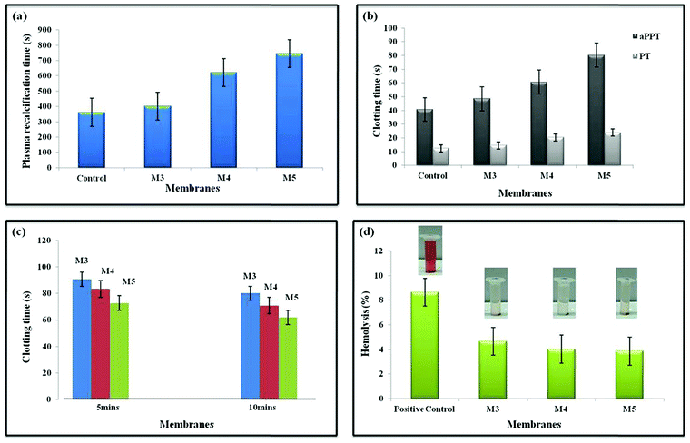
When blood gets into contact with negatively charged surfaces, an intrinsic pathway is initiated, triggering a cascade of Ca2+-dependent activities. Plasma recalcification measures have been used to evaluate the intrinsic coagulation system.64 The presence of turbidity suggests that a clot has formed. Since citrated platelet-deficient plasma (without CaCl2) should not clot, it is utilized as a negative control. In terms of clinical significance, the PRT is nearly comparable to the whole blood coagulation time (CT). It is much more expensive than CT, but it is far more sensitive and efficient, and it is superior to in vivo experiments.65 The PRT of M0 is close to the positive control values. Boosting the AgO@HA proportion leads to the PRT value for M5 being raised in agreement with the aPTT values, which can be seen in Fig. 6(a).66,67The antithrombogenicity of the MMMs was defined using the aPTT and PT. aPTT is a commonly used test to describe blood clotting and any abnormalities in blood plasma when anticoagulants are used. The efficiencies of both the contact activation pathway and the common coagulation pathway are defined by aPTT, which represents the amount of prothrombin, fibrinogen, or other clotting factors in the coagulation pathway, such as factor V and X. It is frequently used in conjunction with PT, an important measure of the extrinsic coagulation pathway. Recent investigations have revealed that the tissue activation pathway (extrinsic) is the predominant pathway that initiates the coagulation cascade, despite the fact that both pathways were previously assumed to be equally important. As documented in other recent publications, the aPTT and PT are routinely employed to test the in vitro blood compatibility of all biomaterials. The aPTT and PT values are plotted in Fig. 6(b), the aPTT increased from 48.5 s in membrane M3 to 80.3 s in membrane M5. Similarly, the PT values also increased from 14.6 s for M3 to 23.9 s for M5. The presence of the AgO@HA nanocomposite at the top surface is responsible for the improvement of the biocompatibility of the PEI/PMMA membranes.68,69
A whole blood clotting experiment for 5 and 10 minutes was performed to evaluate the blood clotting capacity of the polymer membranes in vitro. After incubation with calcified whole blood and the addition of deionized water, red blood cells (RBCs) that were not trapped or unstable in clots were ruptured, resulting in hemoglobin release. As a result, the absorbance at 540 nm can reflect the concentration of free RBCs. Following that, BCI was calculated to quantitatively characterize the inverse side of the degree of clot formation. As shown in Fig. 6c, with medical gauze as a reference, the BCIs of all nanocomposite membranes at 5 and 10 minutes were significantly lower, indicating improved blood clotting capability. Moreover, the haemostatic properties of the nanoparticles of the polymer membrane had an impact. AgO@HA NPs have long been recognised to increase coagulation by causing platelet adhesion and aggregation. As a result, a stable adequate physical support for the AgO@HA NPs-integrated membranes should be supplied to facilitate platelet adhesion and clotting factor binding, resulting in fast clot formation. The integrity of the pure polymer membrane sample's structure would be partially compromised, resulting in an unstable support for clot formation. This is why the pristine PEI/PMMA polymer membrane sample's whole blood clotting value differed significantly from those of all the AgO@HA NPs-infused polymer membrane samples.70
The percentage of hemolysis is indeed essential in influencing a material's bioavailability as blood consists of nearly 48% erythrocytes. A variety of factors can trigger erythrocyte lysis, which leads to the release of haemoglobin and cytoplasm. The mechanical stress of the peristaltic pump, micro-cavities, and germs, jagged edges at the membranes’ entrance, anti-coagulants, and some other factors could all contribute to the lysis. We noticed that all of our developed membranes had a hemolysis ratio of less than 5%, which is far lower than the ASTM F-756-08 Standard's biomaterial safety level. When the concentration of AgO@HA nanoparticles was increased to a certain amount, previous studies demonstrated that they could cause significant hemolysis. The densities of the imides and methacrylate groups were used to modulate the amount of AgO@HA nanoparticles adsorbed on the polymeric thin layers in this work. The membranes lacking AgO@HA nanoparticles (PEI/PMMA) had low hemolysis ratios below 5%, as illustrated in Fig. 6d. Severe hemolysis was detected as the mole ratios of the imides and methacrylate groups were increased, which was induced by the high quantities of AgO nanoparticles.71,72
Platelet adhesion and activation at the interface are critical phases in thrombus formation because adherent and activated platelets will cause plasma clotting to produce a thrombus, which is required for hemostasis. SEM was used to evaluate platelet adherence on the membrane surface, and ELISA kits were used to investigate platelet activation. Numerous platelets attached themselves to and aggregated on the surface of clean PEI/PMMA membranes, as seen in Fig. 7(a). Moreover, due to enhanced hydrophilicity and lower protein adsorption, the AgO@HA NP-modified membranes (M4 and M5) had fewer attached platelets. Furthermore, the platelet shapes on pristine PEI/PMMA surfaces differed significantly from those on the modified membranes. Platelets on the pristine surfaces had an uneven shape, indicating that platelet activation was likely on the surfaces, but platelets on the modified membranes had little pseudopodia. Platelet factor 4 (PF-4) is produced and secreted by activated human platelets and was utilised to investigate platelet activation for the membranes.73–76
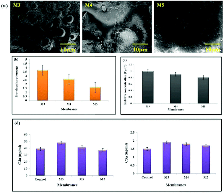 | ||
| Fig. 7 Images of (a) platelet adhesion, (b) protein adsorption, and (c) uremic toxin removal, and (d) complement activation of AgO@HA-PEI/PMMA mixed matrix membranes. | ||
One of the most essential interactions between materials and body fluids has long been thought to be protein adsorption. The deposited proteins will reduce the water flux, lowering the membrane purification efficiency. Furthermore, when employed for sewage treatment, protein adsorption promotes the adhesion and development of microorganisms, resulting in enormous membrane fouling. In the case of hemodialysis, the adsorbed protein is highly likely to induce a series of bio-responses at the interface, such as platelet adhesion and activation, complement activation, macrophage response, and thrombus development. As a result, determining protein adsorption is regarded as critical when evaluating antifouling and the hemocompatibility of membranes. Surface charge, surface roughness, solution environment, protein character most significantly, and surface hydrophilicity are all elements that influence the interaction between proteins and materials’ surfaces. BSA was chosen as a model protein to investigate protein adsorption on the membranes in this investigation, which is one of the most common proteins connected to membrane fouling. As shown in Fig. 7(b), the pristine PEI/PMMA (M3) membrane shows the highest protein adsorption quantified at 3.71 μg cm−2; in contrast, the values were found to be 1.62 μg cm−2 for membrane M5. This is in accordance with the protein adsorption levels steadily decreasing after combining AgO@HA NPs.77–80
The addition of nano-absorbents to the membrane matrix has resulted in the development of mixed membranes that combine the benefits of adsorption and diffusion to improve the membrane purification efficiency. We compared the purifying effectiveness of the AgO@HA NPs-modified membrane counterparts in this study. Creatinine, a primary uremic toxin that must be eliminated during hemodialysis, was utilised as a model toxin to test the purifying efficiency of the composite ultrafiltration membranes. First, the membranes’ adsorption capacities for creatinine were determined, as shown in Fig. 7(c). Increased creatinine adsorption capabilities were found with the use of AgO@HA NPs. The pristine PEI/PMMA membranes, on the other hand, have lower adsorption capabilities than the AgO@HA NPs-modified membranes. During ultrafiltration, the creatinine concentration in the filtrate remained constant for the pristine membrane. There were clear time-dependent variations in creatinine concentration in the nanomaterial-modified samples. At first, adsorption by nanomaterials was crucial in removing creatinine; as a result, only a portion of the toxins were removed by diffusion, resulting in a low creatinine content in the filtrate. The levels of creatinine diffusion rose as the adsorption reached equilibrium, resulting in an increase in creatinine concentration in the filtrate. Finally, as the adsorption by the AgO@HA NPs-modified membrane reached equilibrium, the creatinine was removed through diffusion. As a result, the maximum creatinine concentration was found in the filtrate at this point. The adsorption ability of the blended nanomaterials might greatly improve the hemodialysis membrane's purification efficiency.81
The body's defence mechanism against viruses and other “non-self” things is complement activation. The complement system in humans is made up of 20 or more plasma proteins that act as enzymes or binding proteins. Complement activation can start from either a classical or an alternate pathway, with the end pathway being the same for both. In both processes, an initial enzyme catalyses the production of the C3 convertase, which then forms the C5 convertase, allowing the terminal complement complex to be assembled. By generating a localised inflammatory mediator, complement activation stimulates the host protective mechanism. It could be evaluated by measuring the anaphylactotoxins C3a, C4a, and C5a that are produced. For the complement activation study, we used an ELISA assay to determine the concentrations of C3a and C5a. The assay was also used to assess the AgO@HA-incorporated PEI/PMMA polymer membranes’ blood compatibility. C3a and C5a complement activation markers are both raised in M3, indicating the generation of an acute inflammatory response in the PEI/PMMA pristine membranes. The concentrations of C3a and C5a were 37 ng mL−1 and 1.5 ng mL−1, for the M5 membrane, respectively, as shown in Fig. 7(d). The membranes loaded with AgO@HA have a tendency to inhibit complement activation, and the membrane M5 has the least ability to activate the complement system.82
The silver ion release from the PEI/PMMA polymer membrane samples doped with AgO@HA-NPs (0.5, 1.5 wt%) was investigated to clarify the results of the antimicrobial tests, as shown in Fig. 8. The concentration of silver ions released from the prepared samples after 24 h of incubation in a phosphate buffer solution was determined. As the results indicated, the PEI/PMMA film loaded with 0.5 wt% AgO@HA-NPs showed a small release of silver ions, which amounted to 0.1146![[thin space (1/6-em)]](https://www.rsc.org/images/entities/char_2009.gif) ±
± ![[thin space (1/6-em)]](https://www.rsc.org/images/entities/char_2009.gif) 0.004 mg L−1 and the amount of Ag+ released from the samples increased slowly with increasing content of 1.5% AgO@HA-NPs as 0.1193
0.004 mg L−1 and the amount of Ag+ released from the samples increased slowly with increasing content of 1.5% AgO@HA-NPs as 0.1193![[thin space (1/6-em)]](https://www.rsc.org/images/entities/char_2009.gif) ±
± ![[thin space (1/6-em)]](https://www.rsc.org/images/entities/char_2009.gif) 0.006 mg LA−1, respectively. The Ag+ should be first detached from the HA-NPs and then be released from the PEI/PMMA membrane. Subsequently, a significant amount of Ag+ was released within 24 h, which might result in a good antibacterial effect against Bacillus subtilis and Escherichia coli bacterial cells.83
0.006 mg LA−1, respectively. The Ag+ should be first detached from the HA-NPs and then be released from the PEI/PMMA membrane. Subsequently, a significant amount of Ag+ was released within 24 h, which might result in a good antibacterial effect against Bacillus subtilis and Escherichia coli bacterial cells.83
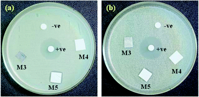 | ||
| Fig. 8 Antimicrobial activities of (a) Bacillus subtilis and (b) Escherichia coli bacterial cells for AgO@HA-PEI/PMMA-mixed matrix membranes. | ||
3.6. Cell-cytocombatibility test
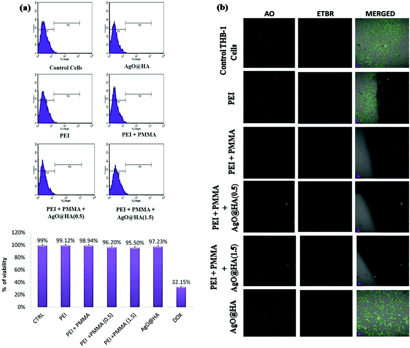
The developed membranes’ cytocompatibility is a critical parameter because they will be utilized for hemodialysis. In this analysis, the survival of seeded Chang Liver cells was determined for 24, 48, and 72 hours, as shown in Fig. 9(a). All of the controls’ (polystyrene cell-culture plate) and the membranes’ formazan absorbance improved, showing cell growth. Membrane M5 multiplied at a greater rate of 0.78 ± 0.01 at 48 hours and 0.95 ± 0.01 at 72 hours. Cell growth and proliferation were faster in membranes containing AgO@HA nanoparticles. With the incorporation of these nanoparticles, the hydrophilicity enhances, because nanoparticles impart high surface energy to these MMMs and may bind and anchor cell proteins, allowing for more efficient propagation. These MMMs have excellent cytocompatibility and could be implemented in any cell-to-cell contact application, such as bio-artificial kidneys and livers.84,85Since this designed membrane is being used for dialysis therapy, cytocompatibility is a significant characteristic. The longevity of the seeded Chang Liver cells was evaluated for 24, 48, and 72 h in this test, as shown in Fig. 9(b). The viable cells’ absorbance of all of the standards (polystyrene cell-culture plate) and the membranes’ improve, signifying cellular proliferation. Membrane M5 replicated much faster, at 0.78 ± 0.01 after 48 hours and 0.95 ± 0.01 after 72 h. In membranes including AgO@HA, cell growth and proliferation were quicker. The hydrophilic nature of these MMMs strengthens with the inclusion of these nanoparticles, as the nanoparticles provide high surface energy to all of them and may bind and anchor cell proteins, allowing for even more effective propagation. These MMMs are cytocompatible and could be used in cell-to-cell contact applications, particularly bio-artificial kidneys and livers.86,87
3.7. Biodegradation studies
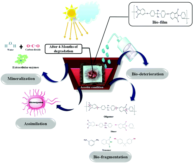
Micro-organisms (primarily bacteria and fungi) frequently produce extracellular enzymes that aid in the degradation of various types of bio- and fossil-based plastics. Bacteria and fungi use various metabolic and enzymatic mechanisms to degrade these polymers into CO2 and H2O. Enzyme nature and catalytic activity vary depending on the microbial species and even within strains. Micro-organisms degrade synthetic and biological plastics via enzymatic hydrolysis, during which extracellular enzymes are secreted. Depending on the environmental factors and the type of microbes, biodegradation could be aerobic or anaerobic. The attack of microbes on the plastic starts the process of microbial biodegradation. The plastic is then converted into monomers by various enzymes, resulting in water-soluble and membrane-permeable molecules. This is referred to as depolymerization. Plastic biodegradation involves bio-deterioration, bio-fragmentation, assimilation, and mineralization (Fig. 10). First, the microorganism connects directly to the plastic surface and changes its physical and chemical characteristics, which is preceded by polymer breakdown (bio-fragmentation) through the use of enzymatic cleavage. Different hydrolysis enzymes, such as proteases, ureases, esterases, or proteases, catalyse the breakdown of polymer bonds. Microbes assimilate the fragmented polymer, which is mineralized into CO2, H2O, CH4, and other compounds. Fig. 11(a) shows the visual images of degraded polymer membranes.88–90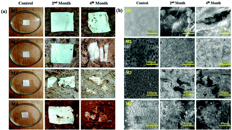 | ||
| Fig. 11 (a) The external appearances of samples with burial times and (b) SEM images of the specimens before and after deterioration. | ||
SEM analysis is a powerful tool for assessing the surface topography of films before and after biological degradation in potting soil and enabled the classification of the degraded residues based on several noteworthy features. We examined the films under SEM before and after degradation to see how biodegradation affected the surface morphology of the nanocomposite polymeric films. Fig. 11(b) shows the changes in the scanning electron microscopy (SEM) images of the samples as a function of burial time during the deterioration process. After four months of degradation, the polymer specimen top had become very abrasive, including multiple splits, as can be seen in the SEM results.91 The M1 polymer membrane had quite a smooth texture. Surface abnormalities and multiple small cavities popped up after 60 days of degradation due to the thermoplastic nature of the polymer. The surfaces of M2 and M3 were littered with corrosive pores, revealing that the samples had eroded. M3 lacked compatibility at a composition ratio of 30![[thin space (1/6-em)]](https://www.rsc.org/images/entities/char_2009.gif) :
:![[thin space (1/6-em)]](https://www.rsc.org/images/entities/char_2009.gif) 70. As an outcome, the PMMA portion of the PEI/PMMA sample was extended and created sequential ridges on the front surface. The cavities and fractures got bigger and wider after 90 days of biological degradation. After composting, SEM micrographs of the deteriorated M4 revealed the roughness of the surface and the formation of pores. Both of these observations show the material's deterioration. After 60 days of composting, M4 showed no noticeable aesthetic alterations. However, the anit-bacterial activities of the nanoparticles incorporated in the membrane protect the M4 sample against degradation, after which it progressively depolymerizes and achieves a good degradation level. The above observation strongly implies that the complex micro-organisms in potting soil ended up going into a more advanced level of deterioration.92,93
70. As an outcome, the PMMA portion of the PEI/PMMA sample was extended and created sequential ridges on the front surface. The cavities and fractures got bigger and wider after 90 days of biological degradation. After composting, SEM micrographs of the deteriorated M4 revealed the roughness of the surface and the formation of pores. Both of these observations show the material's deterioration. After 60 days of composting, M4 showed no noticeable aesthetic alterations. However, the anit-bacterial activities of the nanoparticles incorporated in the membrane protect the M4 sample against degradation, after which it progressively depolymerizes and achieves a good degradation level. The above observation strongly implies that the complex micro-organisms in potting soil ended up going into a more advanced level of deterioration.92,93
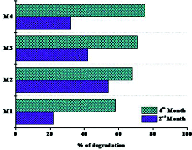
Fig. 12 represents the weight loss percentages of the polymer membranes. The first phase of degradation up to 60 days is referred to as “phase I,” and the second phase of degradation up to 90 days is referred to as “phase II.” The primary factors that influenced the rate of degradation of the films were: (i) the presence of external –OH groups, (ii) the crystallinity of the films, and (iii) the aid with which the cross-linkers were destroyed during the biodegradation. When coming to weight loss percentages, the M1 polymeric film had the minimum weight loss, while the M2 and M3 films had the greatest weight losses. The lower loss of the nanocomposite films in phase I could be accompanied by a decrease in free –OH groups, associated with significantly lower water holding capacity. The nanocomposite films have been noticed to be a little more crystalline than the pristine films, which can also clarify why certain films deteriorated quite slowly in phase I. The possible explanation for M3's fairly low weight reduction, considering the crystallinity, could be due to its wider crystallite size compared to all other films. Besides that, sliver oxide and hydroaxyapatite have antibacterial properties. This can justify why M4 films degraded more slowly in the first phase of degradation. Regrettably, during phase II, the weight losses of the nanocomposite films were considerably greater than that of the pristine film. According to the literature, the crystallinity of the nanocomposites dropped significantly as the amount of inorganic phase increased. The formation of covalent bonds between the inorganic phase and the polymer matrix could explain this result. This is more noticeable with the existence of a lower amount of NPs.94,95 The number of bonds enhances the sense of cross linking, making the organic–inorganic matrix far more messed up, i.e. the polymer starts to lose some of its preliminary crystallinity and becomes even more amorphous. This implies that the nanoparticles were probably broken after an introductory period and that the degradation was aided in phase II, leading to enhanced weight reduction. The results obtained after 120 days of biodegradation reveal that the nanocomposites are far more biodegradable than the pristine membranes. Even though biodegradability occurs in the polymer matrix, enhancing this region helps to improve this property.96,97
4. Conclusions
The purpose of this research was to create new MMMs by incorporating hydrophilic AgO@HA-PMMA nanoparticles into a PEI matrix. We offer a convenient and economical approach for upgrading polyetherimide membranes used for blood contact scenarios by blending polyetherimide with PMMA, which was discovered to be an efficient and relatively sustainable methodology for modifying polymeric membranes with remarkable bioactivity. We exploited AgO@HA in association with the anchoring material PEI/PMMA to customize the porosity of the membranes, optimize the productivity of uremic toxin clearance, and convey bioavailability. The MMMs evoked modest hemolysis, while prolonging clotting times, reducing protein adsorption, and lowering complement adhesion/activation. These membranes also aided Chang Liver cell multiplication and development for up to 72 h. Furthermore, membranes containing more nanoparticles were found to be more cytocompatible. Toxin elimination capabilities and biocompatibility were improved in polymeric membranes using AgO@HA. These findings convincingly show that this simple modification increases the PEI membrane efficiency and biocompatibility and has great promise for the future of hemodialysis research. By using the phase inversion approach, AgO@HA with PEI/PMMA blended membranes were made. The membranes’ shape, hydrophilicity, and stability were investigated, with the results assessed. The following conclusions were drawn from the findings: membrane characterizations by FT-IR confirm the presence of PEI/PMMA and AgO@HA-PEI/PMMA on the membrane surface. Whereas the PEI/PMMA and AgO@HA-PEI/PMMA films exceeded the plain membrane in the aspects of hydrophilic nature, the electrostatic interactions of the PMMA and AgO@HA coating offered vastly increased hydrophilicity and permeation. When it comes to hydraulic pressure susceptibility, the pristine PEI membrane has greater strength, while the modified membranes have a shorter lifespan. This is because the tidy PEI membrane has less porosity and is much more hydrophobic, which renders it more hydraulically resistant. Enhanced-porosity and hydrophilicity-altered membranes, on the other hand, have poor resistance to hydraulic pressure. This is consistent with the findings of the SEM analysis. In a design to simulate the aerobic soil atmosphere, the biodegradation of the PEI/PMMA films integrated with AgO@HA was examined. The preceding experimental studies investigated various aspects of the AgO@HA-PEI/PMMA films. Every one of the films degraded in two phases, with nanoparticles having a negative impact on biodegradation during the first 60 days (phase I), but again the influence was rolled back during the second phase (around 60 and 120 days). Throughout phase I, the bare polymeric films degraded much quicker, while being in phase II the weight loss dropped significantly. The nanoparticle-incorporated films, on the other hand, showed a lower weight loss in phase I, which steadily increased in phase II. After weighing all of the above findings, it was determined that both PEI/PMMA and AgO@HA-PEI/PMMA membranes are the most promising, when blood is exposed to membranes, since they exhibit attractive biocompatible and biodegradable properties. Thus, if further in vivo studies are successful, these membranes containing a composite of nano-functional membrane sheets and bioactive polymers have tremendous potential to be used commercially in eco-friendly hemodialysis modules.Conflicts of interest
There are no conflicts of interest disclosed by the authors.Acknowledgements
The authors express gratitude for the Dean Fellowship's financial support, Department of Chemistry, SRM-IST, Kattankulathur, Chengalpattu-602 302.References
- F. Yang, F. Tao, C. Li, L. Gao and P. Yang, Nat. Commun., 2018, 9, 5443 CrossRef CAS PubMed.
- C. Liu, W. Wang, Y. Li, F. Cui, C. Xie, L. Zhu and B. Shan, J. Membr. Sci., 2019, 576, 48–58 CrossRef CAS.
- Y. Chang, W. Chang, Y. Shih, T. Wei and G. Hsiue, ACS Appl. Mater. Interfaces, 2011, 3, 1228–1237 CrossRef CAS PubMed.
- E. Koh and Y. Lee, Sep. Purif. Technol., 2020, 241, 116657 CrossRef CAS.
- V. Hoseinpour, A. Ghaee, V. Vatanpour and N. Ghaemi, Carbohydr. Polym., 2018, 188, 37–47 CrossRef CAS PubMed.
- Y. C. Cheng, C. C. Fu, Y. S. Hsiao, C. C. Chien and R. S. Juang, J. Mol. Liq., 2018, 252, 203–210 CrossRef CAS.
- H. Waheed and A. Hussain, Bionanoscience, 2019, 9, 256–265 CrossRef.
- U. Teatini, A. Liebchen, L. Nilsson, W. Beck and G. Longhena, Blood Purif., 2016, 41, 80–86 CrossRef CAS PubMed.
- A. Bit and H. Chattopadhyay, Acta Bioeng. Biomech., 2014, 16, 33–44 Search PubMed.
- L. Shan, Y. Sun, F. Shan, L. Li and Z. Xu, J. Mater. Chem. B, 2020, 8, 878–894 RSC.
- F. Prezelus, D. Chabni, L. Barna, C. Guigui and J. Remigy, Green Chem., 2019, 21, 4457–4469 RSC.
- N. Uchiumi, K. Sakuma, S. Sato, Y. Matsumoto, H. Kobayashi, K. Hayashi, T. Kawashki, T. Watanabe, T. Kawasaki, T. Watanabe, A. Itohisa, M. Yokota, K. Okazawa and N. Murotani, Ren. Replace Ther., 2018, 4(32), 1–9 Search PubMed.
- B. Seifert, G. Mihanetzis, T. Groth, W. Albrecht, K. Richau, Y. Missirlis, D. Paul and G. von Sengbusch, Artif. Organs, 2002, 26(2), 189–199 CrossRef CAS PubMed.
- A. Vijayalakshmi, D. L. Arockiasamy, A. Nagendran and D. Mohan, Sep. Purif. Technol., 2008, 62, 32–38 CrossRef CAS.
- S. Rajesh, P. Maheswari, S. Senthilkμmar, A. Jayalakshmi and D. Mohan, Chem. Eng. Commun., 2011, 171, 33–44 CAS.
- T. G. Penaflor Galindo, Y. Chai and M. Tagaya, J. Nanomater., 2019, 3, 1–23 Search PubMed.
- A. Szczes, L. Holysz and E. Chibowski, Adv. Colloid Interface Sci., 2017, 249, 321–330 CrossRef CAS PubMed.
- K. Lin and J. Chang, Hydroxyapatite (Hap) for Biomedical Applications, Woodhead Publ. Ser. Biomater., 2015, 3–19 CAS.
- K. Chen, P. Ustriyana, F. Moore and N. Sahai, ACS Biomater. Sci. Eng., 2019, 5(2), 561–571 CrossRef CAS PubMed.
- C. S. Ciobanu, S. L. Iconaru, I. Pasuk, B. S. Vasile, A. R. Lupu, A. Hermenean, A. Dinischiotu and D. Predoi, Mater. Sci. Eng., C, 2013, 33, 1395–1402 CrossRef CAS PubMed.
- C. Shi, J. Gao, M. Wanga, J. Fu, D. Wang and Y. Zhu, Mater. Sci. Eng. C., 2015, 55, 497–505 CrossRef CAS PubMed.
- U. Erdem, B. Moran Bozer, M. B. Turkoz, A. U. Metin, G. Yıldırım, M. Turk and S. Nezir, J. Asian Ceram. Soc., 2021, 9(4), 1524–1545 CrossRef.
- M. Mahmoudi, I. Lynch, M. R. Ejtehadi, M. P. Monopoli, F. B. Bombelli and S. Laurent, Chem. Rev., 2011, 111, 5610–5637 CrossRef CAS PubMed.
- T. Cedervall, I. Lynch, S. Lindman, T. Berggård, E. Thulin, H. Nilsson, K. A. Dawson and K. S. Linse, Proc. Natl. Acad. Sci. U. S. A., 2007, 104, 2050–2055 CrossRef CAS PubMed.
- Z. J. Deng, M. Liang, M. Monteiro, I. Toth and R. F. Minchin, Nat. Nanotechnol., 2011, 6(1), 39–44 CrossRef CAS PubMed.
- C. J. Wilson, R. E. Clegg, D. I. Leavesley and M. J. Pearcy, Tissue Eng., 2005, 11, 1–18 CrossRef CAS PubMed.
- K. Chen, P. Ustriyana, F. Moore and N. Sahai, ACS Biomater. Sci. Eng., 2019, 5, 561–571 CrossRef CAS PubMed.
- P. Kanagaraj, A. Nagendran, D. Rana, T. Matsuura and S. Neelakandan, Int. J. Biol. Macromol., 2015, 72, 223–229 CrossRef CAS PubMed.
- P. Kanagaraj, S. Neelakandan and A. Nagendran, J. Appl. Polym. Sci., 2014, 131, 40320 CrossRef.
- Z. Ni, X. Gu, Y. He, Z. Wang, X. Zou, Y. Zhaoc and L. Sun, RSC Adv., 2018, 8, 41722 RSC.
- A. Sodagar, A. Akhavan, E. Hashemi, S. Arab, M. Pourhajibagher, K. Sodagar, M. Javad Kharrazifard and A. Bahador, Prog. Orthod., 2016, 17, 40 CrossRef PubMed.
- A. Sumishaa, G. Arthanareeswaran, A. F. Ismail, D. Praveen Kumar and M. V. Shankar, RSC Adv., 2015, 5, 39464–39473 RSC.
- E. C. Kukula, J. Rodrigues de Souza, J. D. Santos, T. M. B. Campos and A. L. S. Boeges, Dent Sci., 2021, 24(3) DOI:10.14295/bds.2021.v24i3.2481.
- C. S. Ciobanu, S. L. Iconaru, C. Chi, A. Costescu, P. Le and D. Predoi, Biomed Res. Int., 2013, 10 Search PubMed.
- C. Rameshkumar, S. Sarojini, K. Naresh and R. Subalakshmi, J. Surface Sci. Technol., 2017, 33(1–2), 12–18 CrossRef CAS.
- S. G. Durak, T. Acar and N. Tufekci, Water Sci. Technol., 2017, 2, 329–339 Search PubMed.
- Y. Liu, X. Ma, K. Sun, K. Yang and F. Chen, J. Solid State Electrochem., 2018, 22, 581–590 CrossRef CAS.
- N. Supraja, T. N. V. K. V. Prasad and E. David, Appl. Nanosci., 2016, 6, 31–41 CrossRef CAS.
- H. Wang, S. Zhang, M. Zhu, G. Sui and X. Yang, J. Electroanal. Chem., 2018, 808, 303–310 CrossRef CAS.
- U. Sathyaa, M. Nithya and Keerthi, Chem. Phys. Lett., 2020, 744, 137201 CrossRef.
- G. Arthanareeswaran, P. Thanikaivelan and M. Raajenthiren, Mater. Sci. Eng. C., 2009, 29, 246–252 CrossRef CAS.
- P. Li, Z. Jia, Q. Wang, P. Tang, M. Wang, K. Wang, J. Fang, C. Zhao, F. Ren, X. Ged and X. Lu, J. Mater. Chem. B, 2018, 6, 7427 RSC.
- M. M. Said, M. Rehan, S. M. El-Sheikh, M. K. Zahran, M. S. Abdel-Aziz, M. Bechelany and A. Barhoum, Nanomaterials, 2021, 11(2), 429 CrossRef CAS PubMed.
- E. Pyo, Y. Kim, J. B. Park and K. Y. Kwon, Bull. Korean Chem. Soc., 2016, 37, 1395–1396 CrossRef CAS.
- S. Kamonwannasit, C. M. Futalan, P. Khemthong, T. Butburee, A. Karaphun and P. Phatai, J. Sol-Gel Sci. Technol., 2020, 96, 452–463 CrossRef CAS.
- B. Seifert, G. Mihanetzis, T. Groth, W. Albrecht, K. Richau, Y. Missirlis, D. Paul and G. von Sengbusch, Int. J. Artif. Organs, 2002, 26(2), 189–199 CrossRef CAS PubMed.
- B. Ghafria, W. Laua, M. Abrib, P. Goha and A. F. Ismaila, J. Water Process., Eng., 2019, 32, 100970 CrossRef.
- S. Senthilkumar, S. Rajesh, A. Jayalakshmi, G. Aishwarya and D. Raju Mohan, J. Polym. Res., 2012, 19, 9867 CrossRef.
- J. Huang, K. Zhang, K. Wang, Z. Xie, B. Ladewig and H. Wang, J. Membr. Sci., 2012, 423, 362–370 CrossRef.
- M. Zhu, J. Lan, C. Tan, G. Sui and X. Yang, J. Mater. Chem. A, 2013, 1–3 Search PubMed.
- V. Kostopoulos, A. Kotrotsos, K. Fouriki, A. Kalarakis and D. Portan, Int. J. Mol. Sci., 2020, 21, 583 CrossRef CAS PubMed.
- P. Kanagaraj, N. Alagumalai, D. Rana, T. Matsuura, S. Neelakandan and K. Malarvizhi, Ind. Eng. Chem. Res., 2015, 54(17), 4832–4838 CrossRef CAS.
- Y. Yang, F. Lu, X. Gao, S. Xie, N. Sun and L. Zheng, J. Membr. Sci., 2015, 490, 38–45 CrossRef CAS.
- R. S. Hebbar, A. M. Isloor, M. S. Abdullah, A. F. Ismail and A. M. Asiri, J. Taiwan Inst. Chem. Eng., 2018, 93, 42–53 CrossRef CAS.
- J. Zeng, X. Sun, L. Zheng, Q. He and S. Li, Chin. J. Chem. Eng., 2012, 20(5), 831–836 CrossRef CAS.
- H. Nagar, K. Swayampakula, B. R. V. Venkata and S. Sridhar, J. Fuel Cell Sci. Technol., 2015, 12(6), 885 Search PubMed.
- G. S. S. Kermpoura, K. D. Papadimitriou, E. N. Skountzos, I. Polyzos, M. G. P. Carbone, A. Kotrotsos, V. G. Mavrantzas, C. Galiotis and C. Tsitsilianis, Nanoscale, 2019, 11, 915–931 RSC.
- V. Kostopoulos, A. Kotrotsos and K. Fouriki, Int. J. Mol. Sci., 2019, 20, 1674 CrossRef CAS PubMed.
- X. Tang, Y. Qin, X. Xu, D. Guo, Y. Wu and R. Li, BioMed Res. Int., 2019, 2019, 2076138 Search PubMed.
- M. Li, P. Xiong, F. Yan, S. Li, C. Ren, Z. Yin, A. Li, H. Li, X. Ji and Y. Zheng, Bioact. Mater., 2018, 3, 1–18 CrossRef PubMed.
- G. Tetteh, A. S. Khan, R. M. Delaine-Smith, G. C. Reilly and I. U. Rehman, J. Mech. Behav. Biomed. Mater., 2014, 39, 95–110 CrossRef CAS PubMed.
- V. Kostopoulos, A. Kotrotsos, K. Fouriki, A. Kalarakis and D. Portan, Int. J. Mol. Sci., 2020, 21, 583 CrossRef CAS PubMed.
- Y. Li, Y. Zhang, S. Zhang and X. Huang, J. Membr. Sci., 2015, 490, 179–189 CrossRef.
- X. Liu, Z. Yang, Y. Zhang, C. Li, J. Dong, Y. Liu and H. Cheng, Int. J. Hydrog. Energy, 2017, 42, 10275–10284 CrossRef CAS.
- Y. S. Lin and C. L. Haynes, J. Am. Chem. Soc., 2010, 132, 4834–4842 CrossRef CAS PubMed.
- N. J. Kaleekkal, D. Rana and D. Mohan, RSC Adv., 2016, 6, 63156 RSC.
- G. J. Dahe, R. S. Teotia, S. S. Kadam and J. R. Bellare, Biomaterials, 2011, 32, 352–365 CrossRef CAS PubMed.
- L. Li, C. Cheng, T. Xiang, M. Tang, W. Zhao, S. Sun and C. Zhao, J. Membr. Sci., 2012, 405–406, 261–274 CrossRef CAS.
- W. Zhao, Q. Mou, X. Zhang, J. Shi, S. Sun and C. Zhao, Eur. Polym. J., 2013, 49, 738–751 CrossRef CAS.
- X. Zhao, J. Gao, X. Hu, H. Guo, F. Wang, Y. Qiao and L. Wang, Appl. Sci., 2018, 8, 1226 CrossRef.
- J. H. Jiang, L. P. Zhu, X. L. Li, Y. Y. Xu and B. K. Zhu, J. Membr. Sci., 2010, 364(1-2), 194 CrossRef CAS.
- C. Nie, L. Ma, Y. Xia, C. He, J. Deng, L. Wang, C. Cheng, S. Sun and C. Zhao, J. Membr. Sci., 2015, 475, 455 CrossRef CAS.
- L. Ma, B. Su, C. Cheng, Z. Yin, H. Qin, J. Zhao, S. Sun and C. Zhao, J. Membr. Sci., 2014, 470, 90 CrossRef CAS.
- A. Sokolov, B. C. Hellerud, T. I. Tonnessen, E. A. Johannessen and T. E. Mollnes, J. Biomed. Mater. Res., Part A, 2013, 101(2), 575–581 CrossRef CAS PubMed.
- A. Higuchi, K. Sugiyama, B. O. Yoon, M. Sakurai, M. Hara and M. Sumita, Biomaterials, 2003, 24(19), 3235–3245 CrossRef CAS.
- K. Chen, P. Ustriyana, F. Moore and N. Sahai, ACS Biomater. Sci. Eng., 2019, 5(2), 561–571 CrossRef CAS PubMed.
- M. Tang, J. Xue, K. Yan, T. Xiang, S. Sun and C. Zhao, J. Colloid Interface Sci., 2012, 386(1), 428 CrossRef CAS PubMed.
- X. Zhao, J. Ma, Z. Wang, G. Wen, J. Jiang, F. Shi and L. Sheng, Desalination, 2012, 303, 29 CrossRef CAS.
- A. Venault, M. R. B. Ballad, Y. H. Liu, P. Aimar and Y. Chang, J. Membr. Sci., 2015, 477, 101–114 CrossRef CAS.
- I. H. Jaffer, J. C. Fredenburgh, J. Hirsh and J. I. Weitz, J. Thromb. Haemostasis, 2015, 13, S72–S81 CrossRef PubMed.
- C. Ye, Q. Gong, F. Lu and J. Liang, Sep. Purif. Technol., 2007, 58, 2–6 CrossRef CAS.
- M. B. Gorbet and M. V. Sefton, Biomaterials, 2004, 25(26), 5681 CrossRef CAS PubMed.
- D. A. Nasrallah and M. A. Ibrahim, J. Polym. Res., 2022, 29(86) DOI:10.1007/s10965-022-02943-5.
- B. Su, P. Fu, Q. Li, Y. Tao, Z. Li, H. Zao and C. Zhao, J. Mater. Sci.: Mater. Med., 2008, 19(2), 745 CrossRef CAS PubMed.
- N. J. Kaleekkal, A. Thanigaivelan, M. Durga, R. Girish, D. Rana, P. Soundararajan and D. Mohan, Ind. Eng. Chem. Res., 2015, 54(32), 7899–7913 CrossRef CAS.
- M. Iqhrammullah, M. Marlina, H. P. S. Abdul Khalil, K. H. Kurniawan, H. Suyanto, R. Hedwig, I. Karnadi, N. G. Olaiya, C. K. Abdullah and S. N. Abdulmadjid, Polymer, 2020, 12, 1317 CAS.
- V. Sharma, J. Vijay, M. R. Ganesh and A. Sundaramurthy, Int. J. Pharm., 2020, 582, 119350 CrossRef CAS PubMed.
- D. V. Sevast’yanov, M. I. Daskovskii, E. A. Shein, S. Yu, S. kripachev, Z. Usagava, G. P. Avilleira and M. G. Batista, Polym. Sci., Ser. D, 2021, 14(1), 119–128 CrossRef.
- A. K. Khan and T. Majeed, J. Nat. App. Sci. Pakistan, 2019, 1(2), 180–184 Search PubMed.
- T. Ahmed, M. Shahid, F. Azeem, I. Rasul, A. A. Shah, M. Noman, A. Hameed, N. Manzoor, I. Manzoor and S. Muhammad, Environ. Sci. Pollut. Res., 2018, 25(1), 1–12 CrossRef PubMed.
- A. A. Shah, F. Hasan, A. Hameed and S. Ahmed, Biotech. Adv., 2008, 26, 246–265 CrossRef CAS PubMed.
- Y. X. Weng, Y. J. Jin, Q. Y. Meng, L. Wang, M. Zhang and Y. Zhong Wang, Polym. Test., 2013, 32, 918–926 CrossRef CAS.
- F. Ruggero, Rob C. A. Onderwater, E. Carretti, S. Roosa, S. Benali, J. M. Raquez, R. Gori1, C. Lubello and R. Wattiez, J. Polym. Environ., 2021, 29, 3015–3028 CrossRef CAS.
- J. Sera, L. Serbruyns, B. D. Wilde and M. Koutny, Polym. Degrad. Stab., 2020, 171, 109031 CrossRef CAS.
- K. Das, D. Ray, N. R. Bandyopadhyay, A. Gupta, S. Sengupta, S. Sahoo, A. Mohanty and M. Misra, Ind. Eng. Chem. Res., 2010, 49, 2176 CrossRef CAS.
- S. Maiti, D. Ray and D. Mitra, J. Polym. Environ., 2012, 20, 749–759 CrossRef CAS.
- V. Machado, S. Amorim, G. Botelho, I. C. Neves and A. M. Fonseca, J. Mater. Sci., 2013, 48, 3578–3585 CrossRef.
Footnote |
| † Electronic supplementary information (ESI) available. See DOI: https://doi.org/10.1039/d2ma00073c |
| This journal is © The Royal Society of Chemistry 2022 |

