 Open Access Article
Creative Commons Attribution 3.0 Unported Licence
Surface-mediated twin polymerisation of 2,2′-spirobi[4H-1,3,2-benzodioxasiline] on multi-walled carbon nanotubes, polyacrylonitrile particles and copper particles†
Lysann
Kaßner
ab,
Thomas
Ebert
c,
Patricia
Godermajer
a,
Volodymyr
Dzhagan
 d,
Dietrich R. T.
Zahn
 be,
Frank
Simon
 f,
Doreen
Dentel
g,
Christoph
Tegenkamp
 g,
Stefan
Spange
 c and
Michael
Mehring
 *ab
*ab
aKoordinationschemie, Technische Universität Chemnitz, 09107 Chemnitz, Germany. E-mail: michael.mehring@chemie.tu-chemnitz.de
bZentrum für Materialien, Architekturen und Integration von Nanomembranen (MAIN), Technische Universität Chemnitz, Rosenbergstraße 6, 09126 Chemnitz, Germany
cPolymermaterialien, Technische Universität Chemnitz, 09107 Chemnitz, Germany
dLashkaryov Institute of Semiconductors Physics, NAS of Ukraine, 45 Nauky av., 03028 Kyiv, Ukraine
eHalbleiterphysik, Technische Universität Chemnitz, 09107 Chemnitz, Germany
fLeibniz-Institut für Polymerforschung Dresden e.V., Hohe Straße 6, 01069 Dresden, Germany
gAnalytik an Festkörperoberflächen, Technische Universität Chemnitz, 09107 Chemnitz, Germany
First published on 21st March 2022
Abstract
Base-catalysed twin polymerisation (TP) of 2,2′-spirobi[4H-1,3,2-benzodioxasiline] (TM) was used to coat substrate particles with a nanostructured phenolic resin–silica hybrid material layer as proven by solid state NMR and IR spectroscopies. Multi-walled carbon nanotubes (MWCNTs), thermally pre-treated polyacrylonitrile particles (ttPAN), and copper particles are used as solid substrates. The coating process is carried out as seed polymerisation using base-modified substrate particles directly as the catalyst in a slurry of diisopropylnaphtalene (DIPN). For MWCNTs as well as ttPAN the tertiary amine 1,4-diazabicyclo[2.2.2]octane (DABCO) is effective as a polymerisation catalyst, which is adsorbed on the substrates prior to polymerisation. The secondary amine pyrrolidine (Py) is an appropriate polymerisation catalyst for TP when chemisorbed on a copper particle surface as shown by X-ray photoelectron spectroscopy (XPS). According to high-angle annular dark-field single transmission electron microscopy (HAADF-STEM) both quantity and thickness of the phenolic resin–silica hybrid layers between 20 nm and 120 nm on MWCNTs, for example, are controlled by the amount of the monomer used. The phenolic resin–silica layer on the particle surfaces is transformed into a homogenous and nanostructured carbon/silica layer on MWCNTs, N-doped carbon and copper as demonstrated by light microscopy, scanning electron microscopy (SEM), energy dispersive X-ray spectroscopy (EDX), and HAADF-STEM measurements. Removal of the silica component by etching with aqueous hydrofluoric acid (HF) provides microporous carbon layers on the nanotubes and particles with surface areas after Brunauer–Emmett–Teller theory (BET) up to 1150 m2 g−1, which are partly graphitic, as proven by Raman spectroscopy.
Introduction
Surface coating with siliceous hybrid materials by means of an aqueous sol–gel process is the most important method to protect substrates against environmental contamination or to build up a barrier against oxygen and water.1–5 Water-free surface coating procedures are required when hydrophobic and water-repellent substrates are used. For this purpose, twin polymerization (TP) was established as a new anhydrous route for the production of nanostructured polymeric organic–inorganic hybrid materials.6–17 This process offers the possibility for avoiding phase separation and it is well suited for surface coating,18–23 thus providing a complementary process to the simultaneous polymerization of common monomers in combination with established sol–gel processes or related procedures.24–30By twin polymerization of a twin monomer, two nanostructured polymers are formed in one reaction step. The phase separation is prevented by mechanistic coupling of both reactions. Different types of TP processes are established, which differ in catalysis, reaction parameters, formed polymers and whether or not a low molecular weight product is split off during the formation of the target hybrid material.7,14 The TP process can be carried out in solution, in melt, as precipitation polymerization or on particle surfaces.6–14,18–21,23 Particularly favourable is the use of the ideal twin monomer (TM) 2,2′-spirobi[4H-1,3,2-benzodioxasiline], which polymerises to a pure phenolic resin–silica hybrid material (see Scheme 1) without the formation of low molecular weight by-products.6,7,14 This TP process of TM can be triggered by various stimuli, namely acid-catalysis, base-catalysis or by heat induction. The mechanistic details of acid-catalysed and heat-induced polymerisation types of TM have been described recently.9,11,14,31–33
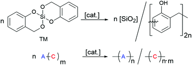 | ||
| Scheme 1 Twin polymerisation of 2,2′-spirobi[4H-1,3,2-benzodioxasiline] (TM) to a phenolic resin–silica hybrid material. | ||
The application of TP as a complementary method to the sol–gel process has several advantages with regard to the process steps (see Table 1). In contrast to the aqueous sol–gel process the twin polymerisation process is fast and leads to complete conversion of the monomer usually within minutes.6,7,14 The twin polymerisation of TM takes place without significant shrinkage due to the ring-opening reaction of the spiro compound and delivers contribution of additional degrees of freedom of both thermal vibration and rotations of the organic polymer.34 In contrast, the shrinkage of a sol–gel layer is difficult to avoid and the aging process must be optimized in a long test series to avoid cracks and inhomogeneities in the layer. For this reason, hybrid layers are often produced by combining sol–gel with epoxide chemistry, for instance.35–41
| Components | Sol–gel coating | TP coating | |
|---|---|---|---|
| Reactants | Hydrolysable monomers, which can consecutively react on the same time scale | Twin monomer | |
| Water | |||
| Optional solvent | (Non-protic) solvent | ||
| Number of components | At least two | At least one | |
| Hard templates | Inorganic oxides | Well suited44–47 | Well suited only for acid catalysis18 |
| Carbon (graphite) | Less suited48 | Well suited only for base catalysis19–21 | |
| Metal | Depends on the properties of the oxidic layer40,49 | Depends on the properties of the oxidic layer14,50 | |
| Thermoplastics | Suitable through appropriate adjustment of the reaction conditions30,36,44 | Suitable through appropriate adjustment of the reaction conditions22,50–52 | |
Differences between the aqueous sol–gel- and TP coatings with regard to the coating process of hard template surfaces are summarized in Table 1.
The overall properties of the hybrid material as prepared by TP, i.e., molecular structure, morphology, domain size and nanostructure, are highly reproducible. Furthermore, the process is extremely robust, and hardly susceptible to external influences such as temperature or solvents. An additional important advantage of TP is the fixed stoichiometry of the twin monomer, which determines the resulting molecular composition of the hybrid material layer. For this reason, lengthy optimization procedures of component mixtures concerning the best-acting composition are not required.
In order to optimise the polymerisation process, the required reaction temperature is determined beforehand via an independent dynamic scanning calorimetry (DSC) experiment.
The coating process occurs fast and the thickness of the hybrid layer on the surface can be precisely controlled by the quantity of the twin monomer used as long as the conversion of the monomer on the surface of the substrate is quantitative.18,19 This scenario can only be accomplished when polymerisation does not take place in the surrounding solution as precipitation polymerisation. Therefore, it is necessary to ensure that the catalyst is completely bonded to or adsorbed on the surface of the substrate. Successful coating using twin polymerisation of TM was carried out on flat (oxidic) surfaces of silica fibres or particles using adsorbed acidic catalysts.18,19 Thus, the surface of the template material to be coated serves as the actual catalyst. In previous studies, derivatives of sulphonic acid, such as toluenesulphonic acid or methanesulphonic acid (MSA), were shown to be effective catalysts, since they are adsorbed by various inorganic oxidic substrate surfaces or covalently bonded on polystyrene.18,20,23 Related to acid-catalysis on oxidic substrate surfaces, base-catalysis by 1,4-diazabicyclo[2.2.2]octane was used for the coating of carbon materials.20,21
The base-catalysed polymerisation of TM works well in the temperature range from 120 °C to 160 °C as proven by solid state 29Si and 13C NMR spectroscopy of the resulting hybrid materials.13,42,43 Compared to the acid catalysis of TP, only very low quantities of base catalysts and higher polymerisation temperatures are required to achieve homogeneous hybrid materials and complete TM conversion.7 Shrinkage of the hybrid material does not take place during the polymerisation process, which prevents cracking or the formation of holes in the coating layer.34 Therefore, high conversion to nanostructured hybrid materials can be achieved without damaging the hybrid layer shape.
The objective of this study is to demonstrate the versatility of the base-catalysed TP of TM as a tool for surface modification, shown here for multi-walled carbon nanotubes (MWCNTs), thermally treated polyacrylonitrile particles (ttPAN), and copper particles (Cu). The general synthetic procedure is illustrated in Scheme 2. These substrates were chosen to demonstrate the versatility of the approach for technologically important materials. For example, MWCNTs are useful as reinforcing filler components for various polymer matrices, as supercapacitators or in lithium sulphur battery applications using carbon/MWCNT nanocomposites.53–57 PAN is applied in clothing, home or outdoor textiles, car interior, or as basis for carbon fibres and starting materials for graphitic carbon with various porosities as used in battery applications.58–62 In particular for battery applications, the enhancement of porosity and integration of active sites are necessary, which are realized by a carbon layer deposition on carbon materials.63,64 Carbon/carbon composites can be applied in high temperature applications due to their thermal resistance. Additionally, they are suitable materials in engineering and the energy sector as brakes, re-entry heat shields, semiconductor manufacturing components or as bio-active prosthetic implants.65,66 Metal particles or nanowires are integrated in polymer matrices to introduce electric conductivity or magnetic properties.67–73 Accordingly, the modification of copper particles is of interest for several applications, such as catalysis,74 toxicity reduction,75 and polymer composite production. Due to their enhanced mechanical, thermal and electric properties copper/graphene composites are potentially applicable as electro-friction materials, for instance.76 Therefore, the pre-functionalization of copper or other substrates with carbon-related materials is necessary to improve the compatibility of substrates with carbon sheets to avoid consecutive particle aggregation within the polymer matrices as well as exfoliation of the coating layer.
 | ||
| Scheme 2 Synthetic strategy for the surface modification of solid substrates by twin polymerisation and transformation of the hybrid material-coated substrates into porous carbon-coated particles. | ||
The synthesis of carbon-coated particles is the focus of this study. These materials are produced in particular by base-catalysed surface polymerisation of TM on particles with subsequent pyrolysis of the phenolic resin–silica layer and etching of silica with hydrofluoric acid. The as-prepared products are characterized by light microscopy, scanning electron microscopy (SEM), energy dispersive X-ray spectroscopy (EDX), high-angle annular dark-field single transmission electron microscopy (HAADF-STEM), IR and Raman spectroscopies, and nitrogen sorption measurements.
Results and discussion
The surface-mediated polymerisation of TM on hard templates in DIPN, in various mass to substrate ratios, is catalysed by the organic bases pyrrolidine (Py) or 1,4-diazabicyclo[2.2.2]octane (DABCO) (see Chart 1). The solvent DIPN was chosen because of its inertness in the aspired chemical reaction, low water content and high boiling point that allows reaction temperatures of up to 230 °C to be used. Advantageously, this maximum temperature would even allow thermally induced twin polymerisation without any external catalyst. Twin polymerisation is triggered directly on the surface of MWCNTs, ttPAN or copper particles as substrates. For coating MWCNTs or ttPAN particles the catalyst is dissolved in a slurry in DIPN. After the catalyst is adsorbed on MWCNTs or ttPAN particles TM is added and the surface-catalysed twin polymerisation occurs. In the case of copper particles as the substrate, the catalyst pyrrolidine should be covalently bonded onto the surface in a preliminary step by heating both components without the solvent. Afterwards TM and DIPN are added for surface-catalysed polymerisation to the slurry. Details of the coating procedure are summarized in Table 2. After separation by filtration or centrifugation the materials were either directly characterised (samples P: hybrid material-coated substrate after polymerization) or pyrolysed (samples C: carbonised samples after coating and pyrolysis) and finally etched (samples E: coated and carbonised samples subsequently etched with aqueous HF). | ||
| Chart 1 Appropriate base catalysts Py and DABCO for surface-mediated polymerisation of TM on MWCNTs, ttPAN, and copper particles and the high boiling solvent DIPN. | ||
| No | Substrate | Base | Mass ratio TM![[thin space (1/6-em)]](https://www.rsc.org/images/entities/char_2009.gif) : :![[thin space (1/6-em)]](https://www.rsc.org/images/entities/char_2009.gif) subs. subs. |
Mass ratio subs.![[thin space (1/6-em)]](https://www.rsc.org/images/entities/char_2009.gif) : :![[thin space (1/6-em)]](https://www.rsc.org/images/entities/char_2009.gif) base base |
Molar ratio TM![[thin space (1/6-em)]](https://www.rsc.org/images/entities/char_2009.gif) : :![[thin space (1/6-em)]](https://www.rsc.org/images/entities/char_2009.gif) base base |
|---|---|---|---|---|---|
| 1_91 | MWCNTs | DABCO | 91![[thin space (1/6-em)]](https://www.rsc.org/images/entities/char_2009.gif) : :![[thin space (1/6-em)]](https://www.rsc.org/images/entities/char_2009.gif) 9 9 |
2.4![[thin space (1/6-em)]](https://www.rsc.org/images/entities/char_2009.gif) : :![[thin space (1/6-em)]](https://www.rsc.org/images/entities/char_2009.gif) 1 1 |
10![[thin space (1/6-em)]](https://www.rsc.org/images/entities/char_2009.gif) : :![[thin space (1/6-em)]](https://www.rsc.org/images/entities/char_2009.gif) 1 1 |
| 1_95 | 95![[thin space (1/6-em)]](https://www.rsc.org/images/entities/char_2009.gif) : :![[thin space (1/6-em)]](https://www.rsc.org/images/entities/char_2009.gif) 5 5 |
1.3![[thin space (1/6-em)]](https://www.rsc.org/images/entities/char_2009.gif) : :![[thin space (1/6-em)]](https://www.rsc.org/images/entities/char_2009.gif) 1 1 |
|||
| 1_99 | 99![[thin space (1/6-em)]](https://www.rsc.org/images/entities/char_2009.gif) : :![[thin space (1/6-em)]](https://www.rsc.org/images/entities/char_2009.gif) 1 1 |
0.3![[thin space (1/6-em)]](https://www.rsc.org/images/entities/char_2009.gif) : :![[thin space (1/6-em)]](https://www.rsc.org/images/entities/char_2009.gif) 1 1 |
|||
| 2_25 | ttPAN | DABCO | 25![[thin space (1/6-em)]](https://www.rsc.org/images/entities/char_2009.gif) : :![[thin space (1/6-em)]](https://www.rsc.org/images/entities/char_2009.gif) 75 75 |
112![[thin space (1/6-em)]](https://www.rsc.org/images/entities/char_2009.gif) : :![[thin space (1/6-em)]](https://www.rsc.org/images/entities/char_2009.gif) 1 1 |
19![[thin space (1/6-em)]](https://www.rsc.org/images/entities/char_2009.gif) : :![[thin space (1/6-em)]](https://www.rsc.org/images/entities/char_2009.gif) 1 1 |
| 2_50 | 50![[thin space (1/6-em)]](https://www.rsc.org/images/entities/char_2009.gif) : :![[thin space (1/6-em)]](https://www.rsc.org/images/entities/char_2009.gif) 50 50 |
44![[thin space (1/6-em)]](https://www.rsc.org/images/entities/char_2009.gif) : :![[thin space (1/6-em)]](https://www.rsc.org/images/entities/char_2009.gif) 1 1 |
|||
| 2_70 | 70![[thin space (1/6-em)]](https://www.rsc.org/images/entities/char_2009.gif) : :![[thin space (1/6-em)]](https://www.rsc.org/images/entities/char_2009.gif) 30 30 |
19![[thin space (1/6-em)]](https://www.rsc.org/images/entities/char_2009.gif) : :![[thin space (1/6-em)]](https://www.rsc.org/images/entities/char_2009.gif) 1 1 |
|||
| 2_88 | 88![[thin space (1/6-em)]](https://www.rsc.org/images/entities/char_2009.gif) : :![[thin space (1/6-em)]](https://www.rsc.org/images/entities/char_2009.gif) 12 12 |
6![[thin space (1/6-em)]](https://www.rsc.org/images/entities/char_2009.gif) : :![[thin space (1/6-em)]](https://www.rsc.org/images/entities/char_2009.gif) 1 1 |
|||
| 3_10 | Copper | Py | 10![[thin space (1/6-em)]](https://www.rsc.org/images/entities/char_2009.gif) : :![[thin space (1/6-em)]](https://www.rsc.org/images/entities/char_2009.gif) 90 90 |
20![[thin space (1/6-em)]](https://www.rsc.org/images/entities/char_2009.gif) : :![[thin space (1/6-em)]](https://www.rsc.org/images/entities/char_2009.gif) 1 1 |
0.6![[thin space (1/6-em)]](https://www.rsc.org/images/entities/char_2009.gif) : :![[thin space (1/6-em)]](https://www.rsc.org/images/entities/char_2009.gif) 1 1 |
| 3_20 | 20![[thin space (1/6-em)]](https://www.rsc.org/images/entities/char_2009.gif) : :![[thin space (1/6-em)]](https://www.rsc.org/images/entities/char_2009.gif) 80 80 |
1.3![[thin space (1/6-em)]](https://www.rsc.org/images/entities/char_2009.gif) : :![[thin space (1/6-em)]](https://www.rsc.org/images/entities/char_2009.gif) 1 1 |
|||
| 3_33 | 33![[thin space (1/6-em)]](https://www.rsc.org/images/entities/char_2009.gif) : :![[thin space (1/6-em)]](https://www.rsc.org/images/entities/char_2009.gif) 67 67 |
2.2![[thin space (1/6-em)]](https://www.rsc.org/images/entities/char_2009.gif) : :![[thin space (1/6-em)]](https://www.rsc.org/images/entities/char_2009.gif) 1 1 |
Base-catalysed twin polymerisation on multi-walled carbon nanotubes (MWCNTs)
In a previous study we demonstrated that DABCO is a suitable base catalyst to produce phenolic resin–silica-coated graphite plates.21 The TP of TM with DABCO on substrate surfaces in a slurry can be well controlled in a way that the polymerisation in the surrounding solution is suppressed. This is in contrast to strong amidine bases such as 1,8-diazabicyclo[5.4.0]undec-7-ene (DBU) or other amines as catalysts, which induce polymerisation simultaneously in the surrounding solution. Similarly, the use of acids on carbon surfaces is not possible because most of the twin monomer fraction polymerises in a precipitation polymerisation in the surrounding solution.20The DABCO-catalysed process was likewise used for coating of MWCNTs as for TP on graphite, but the reaction control had to be adapted.21 For this purpose, MWCNTs were used as a 0.1 weight% suspension in DIPN prepared by treating MWCNTs and DIPN with an ultrasonic rod. Higher concentrations of MWNCTs are not applicable because gelation occurs at higher concentrations.
The mass ratio of TM![[thin space (1/6-em)]](https://www.rsc.org/images/entities/char_2009.gif) :
:![[thin space (1/6-em)]](https://www.rsc.org/images/entities/char_2009.gif) MWCNTs must be ≥ 10
MWCNTs must be ≥ 10![[thin space (1/6-em)]](https://www.rsc.org/images/entities/char_2009.gif) :
:![[thin space (1/6-em)]](https://www.rsc.org/images/entities/char_2009.gif) 1, because only above this concentration a homogeneous layer is formed on the surface of the MWCNTs as proven by SEM. As a result, significant changes in the SEM images of the treated MWCNTs compared to the starting materials could be observed. Quantitative results of MWCNT surface modification by the use of DABCO as the catalyst are compiled in Table 3. Calculated values therein for carbon content and residues after burning are estimated by the TM mass assuming complete conversion to a hybrid material onto the MWCNT surface.
1, because only above this concentration a homogeneous layer is formed on the surface of the MWCNTs as proven by SEM. As a result, significant changes in the SEM images of the treated MWCNTs compared to the starting materials could be observed. Quantitative results of MWCNT surface modification by the use of DABCO as the catalyst are compiled in Table 3. Calculated values therein for carbon content and residues after burning are estimated by the TM mass assuming complete conversion to a hybrid material onto the MWCNT surface.
| No | Mass ratio TM![[thin space (1/6-em)]](https://www.rsc.org/images/entities/char_2009.gif) : :![[thin space (1/6-em)]](https://www.rsc.org/images/entities/char_2009.gif) MWCNTs MWCNTs |
Carbon content [wt%] | Residue TGA [wt%] | ||
|---|---|---|---|---|---|
| Calculated | Exp. | Calculated | Exp. | ||
| MWCNTs | 0![[thin space (1/6-em)]](https://www.rsc.org/images/entities/char_2009.gif) : :![[thin space (1/6-em)]](https://www.rsc.org/images/entities/char_2009.gif) 100 100 |
100 | 98.0 | 0 | 0.8 |
| 1_91P | 91![[thin space (1/6-em)]](https://www.rsc.org/images/entities/char_2009.gif) : :![[thin space (1/6-em)]](https://www.rsc.org/images/entities/char_2009.gif) 9 9 |
65.0 | 48.9 | 20.1 | 36.7 |
| 1_95P | 95![[thin space (1/6-em)]](https://www.rsc.org/images/entities/char_2009.gif) : :![[thin space (1/6-em)]](https://www.rsc.org/images/entities/char_2009.gif) 5 5 |
63.6 | 58.5 | 21.0 | 26.1 |
| 1_99P | 99![[thin space (1/6-em)]](https://www.rsc.org/images/entities/char_2009.gif) : :![[thin space (1/6-em)]](https://www.rsc.org/images/entities/char_2009.gif) 1 1 |
62.1 | 60.4 | 21.8 | 22.2 |
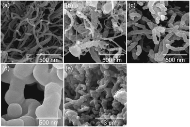
The corresponding SEM micrographs of modified MWCNT samples are shown in Fig. 1. For sample 1_99P the carbon content and residue in TGA measurements after combustion are in good agreement with the calculated values. With decreasing monomer content, the differences with the theoretical values increase. Moreover and contrary to the expectations, the carbon content decreases with decreasing TM content. Additionally, the residual mass after burning increases for lower TM content. These observations indicate either an incomplete conversion of TM or the formation of soluble oligomeric organic reaction products at lower concentrations accompanied by an increased proportion of strongly crosslinked, insoluble SiO2.77 The SEM micrographs (Fig. 1) taken from coated MWCNT samples illustrate that the surface-mediated twin polymerisation of TM on MWCNTs was successful. The individual MWCNT strands are uniformly enveloped by the phenolic resin–silica layer for the samples with 95 wt% (Fig. 1c) and 99 wt% TM (Fig. 1d and e). The sample with 91 wt% TM (Fig. 1b) shows only partly coated MWCNTs and in addition hybrid material particles from precipitation polymerisation in solution. The coating thickness increases with increasing TM to MWCNT ratio (Fig. 1b−d). Aggregation of MWCNTs is observed at high TM concentrations (Fig. 1d and e). The morphology and domain sizes of the obtained hybrid material-coated substrates were further examined by HAADF-STEM measurements (see Fig. 2). These results indicate that the nanostructured phenolic resin–silica hybrid layer does completely cover the individual MWCNT strands (Fig. 2c and d). The thickness of the hybrid layer increases with increasing initial monomer concentration from approximately 20 nm for 1_95P (Fig. 2a and c) to approximately 120 nm for the sample 1_99P (Fig. 2b and d). Hence, the observations in the SEM micrographs (Fig. 1c–e) are confirmed. According to SEM measurements, there is an upward trend for aggregation of the coated nanotubes with increasing monomer content. However, the silica domains are in a size range of a few nanometres (Fig. 2), which is typical for this type of hybrid materials.6–9,13,14 This proves that the process on the surface provides the same microstructure as polymerisation in substance.
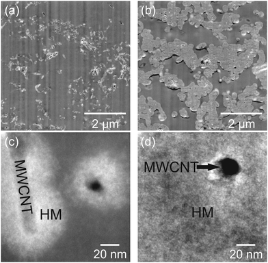 | ||
| Fig. 2 HAADF-STEM micrographs of the products obtained by DABCO-catalysed twin polymerisation of 95 wt% (a and c) and 99 wt% (b and d) of TM on MWCNTs. | ||
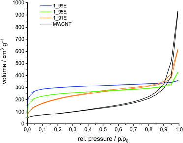
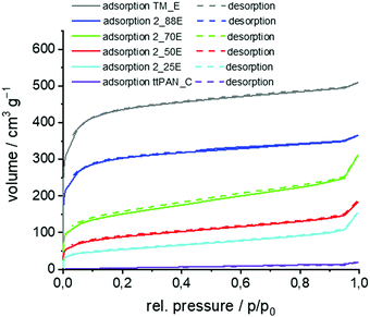
In the next step the phenolic resin–silica hybrid materials were converted at 800 °C under an argon atmosphere into carbon/silica-coated MWCNT composite materials. This thermal conversion was possible without damaging the shape of the nanomaterials. However, a minor volume shrinkage was detected, which originates from the mass loss during the pyrolysis process of the phenolic resin. Etching the carbonised hybrid material with aqueous HF produces porous carbon//MWCNT composites by the removal of SiO2 (Scheme 2). Silicon dioxide of the carbon/silica coated MWCNTs is completely removed with aqueous hydrofluoric acid as proven by TGA measurements (Table S1 in ESI†). The corresponding SEM images of the carbon//MWCNT samples are shown in Fig. 3. The porosity of the binary carbon//MWCNT composites was determined by nitrogen sorption experiments (Fig. 4 and Fig. S1, ESI†). The sorption isotherm plots for the binary carbon//MWCNT composites relate to type I isotherms according to the IUPAC classification, in comparison to a type IV isotherm of mesoporous materials with capillary condensation for MWCNTs.78 For the carbonised and etched samples 1_91E and 1_95E a hysteresis (H3-type of the adsorption isotherms) is observed in addition, which is an indication of slit pores as in the initial sample MWCNTs, which are caused by the agglomerates of the nanotubes. The pore size distribution and the specific surface area of the binary carbon//MWCNT composites are determined by the surface loading amount of the porous carbon layer on MWCNTs (Table 4). Both the microporous pore fraction and the total surface area increase with increasing carbon layer thickness on the MWCNTs. BET surface areas up to approx. 1150 m2 g−1 can be produced. The microporosity of the binary carbon composites is introduced by the newly generated carbon layer, which is obtained from the carbonised and etched hybrid material. Accordingly, with lower TM to MWCNT content the mesoporous fraction increases as indicated by an increasing positive ascending curve with increasing partial pressure.
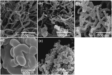 | ||
| Fig. 3 SEM micrographs of carbon//MWCNT composite materials obtained by DABCO-catalysed twin polymerisation of 91 wt% (b), 95 wt% (c), and 99 wt% (d and e) TM on MWCNTs, thermal post-treatment and etching of the silica with HF according to Scheme 2 compared with the pristine MWCNT material (a). | ||
| No | Surface area [m2 g−1] | Overall pore volume [cm3 g−1] | Micropore volume [cm3 g−1] | Micropore fraction [%] | |
|---|---|---|---|---|---|
| BET | QSDFT | ||||
| MWCNTs | 309 | 286 | 0.933 | 0.199 | 21.3 |
| 1_91E | 727 | 533 | 0.706 | 0.190 | 26.9 |
| 1_95E | 907 | 839 | 0.531 | 0.264 | 49.7 |
| 1_99E | 1146 | 1135 | 0.500 | 0.368 | 73.6 |
Raman spectra of the binary carbon//MWCNT composite materials show partly graphitic structures. The carbon content of these composites decreases with increasing the TM to MWCNT reactant ratio, as expected (Table S1 and Fig. S2, ESI†).
Such materials are interesting for applications where high surface areas, different pore sizes and electric conductivity are required.
Base-catalysed twin polymerisation on polyacrylonitrile particles (PAN)
Previously, PAN-based felts were coated by acid-catalysed twin polymerisation, a method, which was not successful for untreated PAN particles.63 Because the material swells in DIPN, the particles were heated at 250 °C under oxidative conditions prior to surface-mediated TP. The as-obtained black, powdery, thermally treated PAN particles (ttPAN) are insoluble with a changed chemical structure as revealed by solid state NMR (Fig. S3, ESI†) and FTIR (Fig. S4, ESI†) spectroscopy measurements. The cyano functionalities react to the complex structure of carbonyl groups and aromatic rings due to oxidative pre-treatment (Scheme S1, ESI†).59,79–90 Compared to pristine PAN, quantitative elemental analysis (Table S2, ESI†) shows decreased contents of carbon, hydrogen and nitrogen in combination with an increased content of other elements, like oxygen.The as synthesised ttPAN particles were suspended in DIPN with subsequent addition of DABCO as the catalyst and stirred overnight to enable the complete adsorption of the catalyst on the particle surface. Polymerisation reactions were carried out at 160 °C with 25 wt%, 50 wt%, 70 wt% and 88 wt% of TM (Table 2 and Table 5). The temperature was chosen based on reference samples (Fig. S5, ESI†). Grey, powdery phenolic resin–silica hybrid material-coated ttPAN particles were obtained by this procedure. The results from quantitative elemental analyses as well as TGA measurements are summarized in Table 5. Similar to the coating of MWCNTs, either the conversion of TM is sometimes incomplete or the reaction leads to the formation of soluble oligomeric organic products, besides the formation of insoluble SiO2 moieties. This can be deduced from the carbon content, the residue in TGA measurements (Fig. S6, ESI† and Table 5) and the yields (Table S3, ESI†).77 With an increase in the TM to ttPAN ratio, the amount of residual SiO2 increases after burning off the organic moiety as expected, and concomitantly, the carbon and nitrogen contents of the samples decrease with increasing TM content. However, there is an increasing deviation of the calculated values from the experimentally measured values of carbon and nitrogen contents and residue in TGA measurements for higher TM to ttPAN ratios.
| No | Mass ratio TM: ttPAN | C content [wt%] | N content [wt%] | Residue TGA [wt%] | |||
|---|---|---|---|---|---|---|---|
| Calc.a | Exp. | Calc.a | Exp. | Calc.a | Exp. | ||
| a Calculated with theoretically used mass of TM and values found for carbon or nitrogen content of ttPAN, respectively, residue TGA of ttPAN. | |||||||
| ttPAN | 0![[thin space (1/6-em)]](https://www.rsc.org/images/entities/char_2009.gif) : :![[thin space (1/6-em)]](https://www.rsc.org/images/entities/char_2009.gif) 100 100 |
— | 61.8 | — | 21.1 | — | 0 |
| 2_25P | 25![[thin space (1/6-em)]](https://www.rsc.org/images/entities/char_2009.gif) : :![[thin space (1/6-em)]](https://www.rsc.org/images/entities/char_2009.gif) 75 75 |
61.6 | 58.7 | 15.7 | 17.9 | 5.7 | 6.5 |
| 2_50P | 50![[thin space (1/6-em)]](https://www.rsc.org/images/entities/char_2009.gif) : :![[thin space (1/6-em)]](https://www.rsc.org/images/entities/char_2009.gif) 50 50 |
61.5 | 54.4 | 10.3 | 14.6 | 11.3 | 11.2 |
| 2_70P | 70![[thin space (1/6-em)]](https://www.rsc.org/images/entities/char_2009.gif) : :![[thin space (1/6-em)]](https://www.rsc.org/images/entities/char_2009.gif) 30 30 |
61.4 | 52.2 | 6.3 | 12.5 | 15.4 | 17.5 |
| 2_88P | 88![[thin space (1/6-em)]](https://www.rsc.org/images/entities/char_2009.gif) : :![[thin space (1/6-em)]](https://www.rsc.org/images/entities/char_2009.gif) 12 12 |
61.3 | 54.0 | 2.3 | 4.1 | 19.6 | 23.1 |
| TM_P | 100![[thin space (1/6-em)]](https://www.rsc.org/images/entities/char_2009.gif) : :![[thin space (1/6-em)]](https://www.rsc.org/images/entities/char_2009.gif) 0 0 |
61.2 | 47.3 | 0 | 0 | 22.1 | 34.3 |
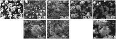
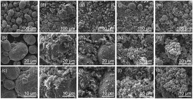
ATR-FTIR- and solid state 13C{1H} and 29Si{1H} CP-MAS NMR spectroscopic measurements of the samples demonstrate the successful polymerisation of TM to phenolic resin–silica hybrid materials (Fig. S7–S9 in ESI†). The phenolic resin–silica-coated ttPAN particles and untreated ttPAN particles were examined by light microscopy (Fig. S10, ESI†) and SEM (Fig. 5 and Fig. S11, ESI†) to evaluate the homogeneity of the products. The substrate surface itself is uneven and the particles are 10–50 μm in diameter. During polymerisation small hybrid particles are produced that enclose the substrate particles, shown for sample 2_88P for example (Fig. 5h, i and Fig. S11, ESI†). The surface coating of ttPAN was additionally confirmed by SEM and EDX analysis of the modified ttPAN particles 2_25P (see Fig. S12 in ESI†). As an indication for the successful surface modification of the ttPAN particles, likewise silicon and oxygen of the hybrid material originating from TP are detected. Nevertheless, precipitation polymerization of TM in the surrounding solvent cannot be fully suppressed. Samples 2_25P and 2_50P show a significant amount of hybrid material particles in addition to coated substrate particles as shown by SEM.
The hybrid material-coated ttPAN particles were carbonised under argon and etched with aqueous HF resulting in a carbon layer on a nitrogen-doped carbon material (N-carbon). For comparison, one sample was additionally etched with aqueous NaOH (5 M, 3 h reflux). The obtained BET surface area was more than 300 m2 g−1 higher for aqueous HF etching (1150 m2 g−1versus 1490 m2 g−1) and thus, all composite materials were finally etched using aqueous HF. The comparative results of nitrogen sorption measurements are shown in the ESI† (Table S4 and Fig. S13). The corresponding SEM micrographs of the produced carbon//N-carbon composites are shown in Fig. 6. The morphology of the particles showing high porosity is comparable to that of those before carbonisation and etching. ttPAN_C with a BET surface area of about 30 m2 g−1 is non- or macroporous as indicated by the type II isotherm in nitrogen sorption measurements (Table 6, Fig. 7 and Fig. S14, ESI†).78 In contrast to the macroporosity and the low surface area of the carbonised ttPAN substrate, TM_E possesses a large surface area of 1600 m2 g−1 resulting in a type I loop of hysteresis combined with type I isotherm indicating mainly microporosity. As a result of increasing the TM portion, the coated particles show (i) increasing surface areas, (ii) increasing overall pore volumes, and (iii) increasing microporous fractions after pyrolysis under argon and subsequent etching. Thus, the surface area, overall pore volume and the bimodal distribution of meso- and microporosity can be precisely adjusted by coating ttPAN particles with varying TM portions. All carbon//N-carbon samples show D and G bands in their Raman spectra at around 1340 cm−1 and 1600 cm−1 indicating partially graphitic structures (Fig. S15, ESI†). The almost complete removal of silica from carbonised and etched samples by aqueous HF etching is confirmed by TGA measurements (Table S5, ESI†). With increasing TM content, the carbon content increases in carbonised and etched samples (Table S5, ESI†) due to increasing amounts of carbon-rich pyrolysed phenolic resin besides decreasing the ttPAN content. This is opposite to the samples after the coating procedure (Table 5) because of the increasing silica content in the coated samples. The nitrogen content decreases for pyrolysed and etched samples with increasing TM to ttPAN ratio both before (Table 5) and after (Table S5, ESI†) the carbonising and etching processes, as expected.
| No | Surface area [m2 g−1] | Overall pore volume [cm3 g−1] | Micropore volume [cm3 g−1] | Micropore fraction [%] | |
|---|---|---|---|---|---|
| BET | QSDFT | ||||
| ttPAN_C | 26 | 12 | 0.0247 | 0.0002 | 0.8 |
| 2_25E | 189 | 173 | 0.1819 | 0.0469 | 25.8 |
| 2_50E | 315 | 273 | 0.2382 | 0.0971 | 40.8 |
| 2_70E | 539 | 507 | 0.3979 | 0.1382 | 34.7 |
| 2_88E | 1140 | 1128 | 0.5101 | 0.3544 | 69.5 |
| TM_E | 1655 | 1512 | 0.7156 | 0.5098 | 71.2 |
Base-catalysed twin polymerisation on copper particles
Commercially available copper particles were used for the investigation of the base-catalysed coating by TP. In accordance with the literature, XPS measurements indicate that at least a partial thin copper(I) oxide or copper(II) oxide or hydroxide layer is present (see Fig. S16 in the ESI†).91,92 Furthermore, the surface is contaminated with long-chain hydrocarbons (285.0 eV), esters (286.1 eV, 286.8 eV and 288.4 eV) and carboxylates (289.4 eV; see Fig. S17 in the ESI†). These copper particles did not induce the surface-mediated twin polymerisation and the acid-catalysed TP of TM gave polymerisation of TM only in the surrounding solvent. However, base-catalysis using pyrrolidine (Py) was successful. Py is first pre-adsorbed and then thermally treated. These Py-modified Cu particles (Py/Cu) were used for the experiments. Py interacts strongly with the copper surface (Scheme 3) as shown by XPS studies. The XPS N1s peak (Fig. S18, ESI†) of Py/Cu at 399.7 eV indicates two different bonding states at 399.0 eV and 400.0 eV of the nitrogen atoms of adsorbed Py. Concluding from the XP spectra, it is suggested that the secondary amine reacted with the copper as well as was physisorbed onto the copper surface (Scheme 3), in accordance with the literature.91–97 Reactions under physisorption (2–4) as well as reactions with carboxylate-containing contaminants (1) are assumed. The adsorption process at Cu–OH and Cu–O sites can be classified as a hydrogen bonding reaction (3, 4).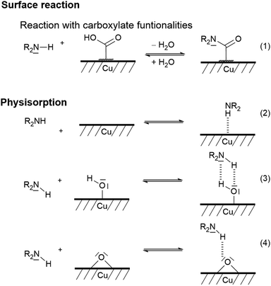 | ||
| Scheme 3 Suggested bonding states of secondary amines on copper surfaces according to the literature.91 | ||
However, ammonium-like species are unlikely as their signal should appear at a higher energy of about 402 eV.92
The Py/Cu particles were directly used as the substrate for seed polymerisation in combination with the TM (further details in the Experimental part).
As shown by DSC measurements (Fig. 8), the Py-modified copper surface is suitable to catalyse the surface-mediated twin polymerisation of TM. For the DSC measurements, pure TM, TM in the presence of untreated copper powder (TM + Cu) and TM with Py/Cu were used. By using Py/Cu, the necessary onset temperature of the exothermic polymerisation reaction of TM is reduced significantly to 116 °C, compared to TM with an onset polymerisation temperature of 168 °C and to untreated Cu with an onset temperature of 131 °C.
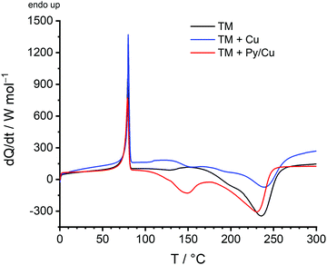 | ||
| Fig. 8 DSC measurements of the twin monomer 2,2′-spirobi[4H-1,3,2-benzodioxasiline] (TM) (black), a mixture of TM and copper (blue), and a mixture of TM and Py/Cu (red). | ||
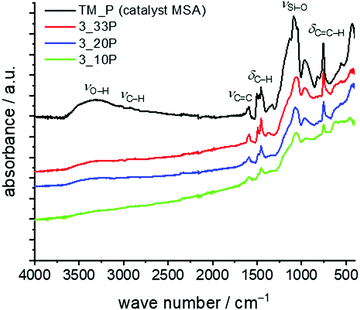
For the seed polymerisation, the Py/Cu particles were mixed with 10–33 wt% of the monomer and the solvent DIPN was added under an inert atmosphere (argon). The slurry was heated to 160 °C for 6 h to ensure the complete polymerisation of the twin monomer. After separation and drying of the coated particles quantitative elemental analyses and TGA show the composition of the materials (Table 7). Due to the oxidative conditions in thermogravimetric measurements under air, copper reacts to copper(II) oxide and thus, the residues found exceed 100% by weight. However, the values for samples 3_20P and 3_10P are close to the theoretical value for decomposed hybrid materials on copper particles assuming that exclusively silica and CuO remain (see Table 7). As a result of incomplete conversion of TM and side reactions, which provide soluble products, we suggest that the carbon content of TP is lower than theoretically expected. At higher TM concentrations the adsorbed catalyst is no longer accessible with increasing reaction time and increasing layer thickness of the hybrid material and, thus, the polymerization stops. Therefore, synthesis of copper particles with a thin shell of a nanostructured hybrid layer is more appropriate. However, the formation of the phenolic resin–silica layer is proven by FTIR spectroscopy (Fig. 9). Characteristic IR bands of the phenolic resin–silica hybrid material are assigned for all samples. The intensity of the IR bands of the hybrid layer increases with a higher monomer content. The FTIR spectrum of an independently prepared phenolic resin–silica hybrid material prepared by MSA-catalysed precipitation polymerisation of TM was used as the reference for structure assignment.
| No | Mass ratio TM![[thin space (1/6-em)]](https://www.rsc.org/images/entities/char_2009.gif) : :![[thin space (1/6-em)]](https://www.rsc.org/images/entities/char_2009.gif) Cu Cu |
Carbon content [wt%] | Residue TGA [wt%] | ||
|---|---|---|---|---|---|
| Calc. | Found | Calc. | Found | ||
| 3_10P | 10![[thin space (1/6-em)]](https://www.rsc.org/images/entities/char_2009.gif) : :![[thin space (1/6-em)]](https://www.rsc.org/images/entities/char_2009.gif) 90 90 |
6.2 | 4.9 | 114.9 | 114.9 |
| 3_20P | 20![[thin space (1/6-em)]](https://www.rsc.org/images/entities/char_2009.gif) : :![[thin space (1/6-em)]](https://www.rsc.org/images/entities/char_2009.gif) 80 80 |
12.4 | 9.5 | 104.6 | 106.5 |
| 3_33P | 33![[thin space (1/6-em)]](https://www.rsc.org/images/entities/char_2009.gif) : :![[thin space (1/6-em)]](https://www.rsc.org/images/entities/char_2009.gif) 67 67 |
20.4 | 11.8 | 91.2 | 105.6 |
SEM micrographs of the samples 3_10P, 3_20P and 3_33P (Fig. S19 in ESI†) show powdery particles without agglomeration. The coating of Cu particles with the phenolic resin–silica layer is additionally confirmed by EDX analysis of the modified Cu particles 3_20P (see Fig. S20 in ESI†). As an indication for the successful modification of the metal particles, likewise silicon and oxygen from the hybrid material of TP are detected at positions with high copper contents. According to SEM results, hybrid material from precipitation polymerization is not fully suppressed, but HAADF-STEM measurements clearly show the coatings of nanostructured phenolic resin–silica hybrid material on copper particles of varying thickness from 75–200 nm (Fig. 10).
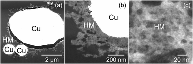 | ||
| Fig. 10 HAADF-STEM micrographs of the hybrid materials obtained by surface TP using 33 wt% 2,2′-spirobi[4H-1,3,2-benzodioxasiline] TM on pyrrolidine-modified copper Py/Cu (a–c). | ||
Conclusions
The reported studies demonstrate the potential for surface-mediated twin polymerisation on chemically quite different substrates. This was exemplarily shown by the base-catalysed synthesis of nano-structured phenolic resin–silica hybrid material-coated MWCNTs, thermally treated PAN, and copper particles. The polymerisation process is best carried out in slurries of the high-boiling solvent DIPN. Suitable external catalysts for surface-mediated twin polymerisation are DABCO for MWCNTs and ttPAN, as well as pyrrolidine for copper. Actually, the base-modified substrate particles serve as the catalyst for the polymerisation of TM. The layer thickness can be adjusted by the TM![[thin space (1/6-em)]](https://www.rsc.org/images/entities/char_2009.gif) :
:![[thin space (1/6-em)]](https://www.rsc.org/images/entities/char_2009.gif) MWCNT ratio with layer thicknesses in the nm range from approximately 20 nm to 120 nm. Carbonisation and subsequent etching of porous silica–carbon materials yield binary porous materials with high specific surface areas up to 1150 m2 g−1. The microporous pore volume fraction of carbonised and etched materials increases with increasing TM concentration. Etching is best carried out using aqueous HF instead of sodium hydroxide solution.
MWCNT ratio with layer thicknesses in the nm range from approximately 20 nm to 120 nm. Carbonisation and subsequent etching of porous silica–carbon materials yield binary porous materials with high specific surface areas up to 1150 m2 g−1. The microporous pore volume fraction of carbonised and etched materials increases with increasing TM concentration. Etching is best carried out using aqueous HF instead of sodium hydroxide solution.
In conclusion, the base-catalysed twin polymerisation of TM is a simple method for coating various substrates with a nanostructured hybrid material layer resulting in porous binary carbon//substrate composites after carbonisation and subsequent etching.
The substrates modified in this way can be used directly before and after inert carbonisation and etching. For example, the materials are applicable as filler components in microdevices with matrix-matched surface properties or in batteries where conductivity, high porosity or the integration of active centres is required.
Experimental section
Methods
Nitrogen physisorption isotherms were obtained at −196 °C using an Autosorb IQ2 apparatus (Quantachrome). All MWCNT samples were heated for two hours at 150 °C and ttPAN samples were activated in vacuum at 80 °C for 48 hours prior to the measurements. Specific surface areas were calculated as the multipoint BET surface area, choosing the relevant range with the help of the micropore BET assistant. The pore size distributions were estimated according to the quenched solid density functional theory equilibrium model (QSDFT, for slit/cylindrical pores) for carbon samples using the ASiQwin 4.0 software (Quantachrome). The total pore volume and specific micropore volume were calculated using the above-mentioned DFT models. The microporous fraction was calculated by the values of cumulative pore volume of all pores and the cumulative pore volume of micropores up to 2 nm in diameter. For verification of accurate measurements, an aluminium oxide standard with a BET surface of 5.86 m2 g−1 with a tolerance of ±0.2 m2 g−1 was used.ATR-FTIR spectra were obtained with a Golden Gate ATR accessory from LOT-Oriel GmbH & Co. KG, Darmstadt, using a BioRad FT-IR 165 spectrometer with a resolution of 4 cm−1 (Bio-Rad Laboratories, Philadelphia, PA, USA).
DSC experiments were performed with a DSC 1 calorimeter (Mettler Toledo) in 40 μL aluminium crucibles. The measurements were performed at a heating rate of 10 K min−1 in the temperature range of 25 to 300 °C under a nitrogen flow of 50 mL min−1. For calibration, the melting temperatures of the standard substances zinc and indium were determined from the onset points with a maximum limit of tolerance of ±1 K.
Scanning electron microscopy images were recorded using a Nova NanoSEM (FEI) using a pressure of pSEM ≈ 6.5 × 10⁻⁵ mbar, and an acceleration voltage of 5–30 kV. EDX spectroscopy and elemental mappings were performed using a Nova NanoSEM 200 instrument combined with a Si drift detector XFlash 5010 (Bruker AXS).
Solid state NMR spectra were collected at 9.4 T using an Avance 400 spectrometer (Bruker) equipped with double tuned probes capable of magic angle spinning (MAS). Solid state 13C{1H} CP MAS NMR spectra were recorded at 100.6 MHz in 3.2 mm standard zirconium oxide rotors (Bruker) spinning at 15 kHz. Cross polarization (CP) with a contact time of 3 ms was used to enhance sensitivity. The recycle delay was 5 s. The spectra were referenced externally to Si(CH3)4 (δ = 0.00 ppm) as well as to adamantine (δ = 38.48 ppm for 13C) as a secondary standard. Solid state 29Si{1H} CP MAS NMR spectroscopy was performed at 79.5 MHz using 3.2 mm standard zirconium oxide rotors (Bruker) spinning at 12 kHz. The contact time was 3 ms and the recycle delay was 5 s. Shifts were referenced externally to Si(CH3)4 (δ = 0.00 ppm) with Si[Si(CH3)3]4 (δ = −9.8 ppm, −135.2 ppm) as the secondary standard. All spectra were collected with 1H decoupling using a two-pulse phase modulation sequence.
Quantitative elemental analysis of the elements C, H and N was performed with a varioMICRO cube for CHNS analysis from Elementar Analysensysteme GmbH. Acetanilide was used as the standard substance before the measurements for checking the serviceability of the analyzer and determining a correction factor on daily basis. Common standard deviation is <0.1%. Measurements were repeated twice.
Thermogravimetric measurements were realized using a TGA/DSC3+ with a XP1U balance (HTSO801RO/GC401, Mettler Toledo). The samples were heated under a constant air flow of 20 mL min−1 under oxidative conditions in corundum crucibles. The TGA/DSC3+ instrument is calibrated internally by weight and calibrated by temperature measurements with indium, aluminium, gold, and palladium with a maximum accepted temperature tolerance of ±0.4%.
For Raman spectroscopic measurements at room temperature two different instruments were used indicated by the laser wavelength. The spectra are normalized to the G band intensity. A wavelength of 514.7 nm was used at the LabRam HR800 micro-Raman System with a resolution of 5 cm−1 and a laser power of 0.1 mW. For a wavelength of 532 nm an inVia Raman microscope (Renishaw) was used with a 20 s exposure time and a 0.5 mW laser power.
X-Ray photoelectron spectroscopy measurements (XPS) were carried out using an AXIS ULTRA spectrometer (Kratos Analytical, England). The spectrometer was equipped with a monochromatic Al Kα (hν = 1486.6 eV) X-ray source of 300 W at 15 kV. The kinetic energy of photoelectrons was determined with a hemispheric analyser set to pass an energy of 160 eV for wide-scan spectra and 20 eV for high-resolution spectra. During all measurements, electrostatic charging of the sample was avoided by means of a low-energy electron source working in combination with a magnetic immersion lens. Later, all recorded peaks were shifted by the same value that was necessary to set the C 1s peak to 285.00 eV. The high-resolution spectra were deconvoluted by means of the Kratos spectra deconvolution software.
High-angle annular dark field scanning transmission electron microscopy measurements were carried out using a Technai F-20 instrument (Fei) with HAADF-STEM- and EDXS-detectors. For preparation the particles were embedded in an epoxy resin between two silicon wafers and cured at 100 °C. Afterwards, the samples were placed on a copper loop and ground to a thickness of 10 μm. Then, the samples were thinned using a precision ion polishing system (Ar) with 1–3 keV for translucence.
The light microscopy images were recorded with an Axio Scope.A1 (Zeiss), equipped with an HBO 100 illuminator and a halogen lamp Hal 100 with polarized light in bright-field or dark-field modus as stated in the images.
Materials
The solvents n-hexane and toluene were dried using sodium, freshly distilled before use and handled under argon. Di-isopropylnaphthalene (DIPN, BASF SE) was dried with a molecular sieve, 4 Å, and stored under an argon atmosphere. 2,2′-Spirobi[4H-1,3,2-benzodioxasiline] TM was prepared according to the literature.6 However, it must be noted that twin monomers are hydrolytically susceptible, which requires careful drying of all reaction components and an inert reaction atmosphere.Silica in carbonised hybrid material particles was etched using hydrofluoric acid (HF, 40%) from AppliChem GmbH. 1,4-Diazabicyclo[2.2.2]octane (Sigma-Aldrich) and pyrrolidine (Acros) were purchased and used as received.
MWCNTs were purchased from ARRY (stock number ARM003) with an outer diameter about 10–20 nm, a length < 20 μm, purity > 95 wt% and ash < 1.0 wt%.
Polyacrylonitrile powder (HOMO-PAN with more than 99.5% acrylonitrile, a molecular weight of 200.000 g mol−1, and an average particle size of 40 μm) was used as received from DOLAN GmbH for further thermal treatment.
Copper powder was commercially procured from Alfa Aesar with 625 mesh, APS 2–3.5 micron and 99% purity.
Procedures
Oxidation and coating of PAN particles
The thermal treatment procedure is explained in detail in the ESI† including elemental analyses, solid state NMR and FTIR spectroscopic measurements. The thermally treated PAN (ttPAN) was used for further experimental studies.Under an inert atmosphere 0.2 g of ttPAN was stirred in 50 mL of dried DIPN together with DABCO (nTM![[thin space (1/6-em)]](https://www.rsc.org/images/entities/char_2009.gif) :
:![[thin space (1/6-em)]](https://www.rsc.org/images/entities/char_2009.gif) nDABCO = 19
nDABCO = 19![[thin space (1/6-em)]](https://www.rsc.org/images/entities/char_2009.gif) :
:![[thin space (1/6-em)]](https://www.rsc.org/images/entities/char_2009.gif) 1) over night. Afterwards, the twin monomer was added in an appropriate amount. For polymerisation, the mixture was heated to 160 °C for 6 h under an inert atmosphere and cooled to room temperature. The supernatant solvent was decanted and the remaining slurry was filtered. The solid residue was rinsed with DCM extensively and dried under vacuum.
1) over night. Afterwards, the twin monomer was added in an appropriate amount. For polymerisation, the mixture was heated to 160 °C for 6 h under an inert atmosphere and cooled to room temperature. The supernatant solvent was decanted and the remaining slurry was filtered. The solid residue was rinsed with DCM extensively and dried under vacuum.
Modification and coating of copper particles
The base-loading of the metal particles was carried out in a round bottom flask. 1 mL of pyrrolidine was added to approximately 1 g of copper powder. This mixture was refluxed for 3 h. Then the amine was completely distilled off. The copper powder was dried in vacuum to constant weight and stored under an argon atmosphere.The modified copper particles were transferred to a silanized two necked round bottom flask under an inert atmosphere. The particles were suspended in DIPN and an appropriate amount of TM was added. The surface-catalysed seed twin polymerisation of TM on functionalized copper particles was performed in a slurry in DIPN under argon by heating to 160 °C and maintaining this temperature for 6 h. Afterwards the hybrid material was collected by centrifugation, washed three times with toluene, and dried in vacuum at 110 °C.
Carbonisation and etching
For carbonisation the hybrid material-coated MWCNTs and copper particles were placed in a platinum crucible and inserted into a quartz tube or were inserted directly into the quartz tube in the case of coated ttPAN. After rinsing with argon for 30 minutes (80 mL min−1) the material was heated under a constant argon flow to 800 °C at a rate of 4.3 K min−1 and this temperature was maintained for 3 h. Afterwards the samples were slowly cooled to room temperature under an argon atmosphere.For the removal of silica, the carbon/silica composites were inserted into a polypropylene vessel, which was placed above an aqueous solution of Ca(OH)2 for safety reasons. The composite material was covered with hydrofluoric acid for 72 h in the cases of MWCNTs and copper particles. Carbonised ttPAN was stored for 96 h with aqueous HF. Please pay attention when working with extremely hazardous hydrofluoric acid; it is highly corrosive and toxic. Before starting your work, inform yourself comprehensively about the safety instructions and measures. Take appropriate safety precautions. Work in a well-ventilated fume hood in a laboratory equipped with a safety shower and other safety appliances. Never work alone with aqueous HF.
After isolation of the etched samples by filtration the carbon material was washed thoroughly with deionized water and ethanol. Finally, the porous carbon was dried in vacuum at 110 °C.
Author contributions
Lysann Kaßner: writing – original draft, editing, investigation, methodology, project administration, and formal analysis; Thomas Ebert: writing – original draft, investigation, methodology, project administration, and formal analysis; Patricia Godermajer: investigation and formal analysis; Volodymyr Dzhagan: investigation; Dietrich R. T. Zahn: investigation and validation; Frank Simon: investigation and validation; Doreen Dentel: investigation; Christoph Tegenkamp: investigation and validation; Stefan Spange: writing – editing and review, conceptualization, funding acquisition, resources, and supervision; Michael Mehring: writing – editing and review, conceptualization, funding acquisition, resources, and supervision.Conflicts of interest
There are no conflicts to declare.Acknowledgements
Financial support by the DFG Sp 392/31-2 and DFG FG 1497 is greatly acknowledged. PAN particles were provided by courtesy from DOLAN GmbH. We thank the heads of the Professorships Chemische Technologie, Physikalische Chemie, Polymerchemie, and Materialien für innovative Energiekonzepte for the opportunity of doing a part of Raman spectroscopy, TGA, HF etching, solid state NMR and light microscopy measurements as well as A. Schäfer for Raman-, S. Scholz for TGA-, S. Hentschel for BET-, and I. Köwitsch for light microscopy measurements of the samples. M. Kreijca is acknowledged for HF etching of the samples. We thank Professorship Organische Chemie for quantitative elemental analyses and Dr P. Müller from Department of Polymer Physics, BASF SE, for HAADF-STEM measurements.References
- D. Wang and G. P. Bierwagen, Prog. Org. Coat., 2009, 64, 327–338 CrossRef CAS.
- J. H. Fendler, Nanoparticles and Nanostructured Films: Preparation, Characterization, and Applications, Wiley, Hoboken, 2008 Search PubMed.
- K. Rose, Surf. Coat. Int. Part B Coat. Trans., 2003, 86, 279–285 CrossRef CAS.
- D. R. Vollet, L. M. Nunes, D. A. Donatti, A. Ibañez Ruiz and H. Maceti, J. Non-Cryst. Solids, 2008, 354, 1467–1474 CrossRef CAS.
- S. Amiri and A. Rahimi, Iran. Polym. J., 2016, 25, 559–577 CrossRef CAS.
- S. Spange, P. Kempe, A. Seifert, A. A. Auer, P. Ecorchard, H. Lang, M. Falke, M. Hietschold, A. Pohlers, W. Hoyer, G. Cox, E. Kockrick and S. Kaskel, Angew. Chem., Int. Ed., 2009, 48, 8254–8258 CrossRef CAS PubMed.
- T. Ebert, A. Seifert and S. Spange, Macromol. Rapid Commun., 2015, 36, 1623–1639 CrossRef CAS PubMed.
- T. Löschner, A. Mehner, S. Grund, A. Seifert, A. Pohlers, A. Lange, G. Cox, H.-J. Hähnle and S. Spange, Angew. Chem., Int. Ed., 2012, 51, 3258–3261 CrossRef PubMed.
- P. Kempe, T. Löschner, A. A. Auer, A. Seifert, G. Cox and S. Spange, Chem. – Eur. J., 2014, 20, 8040–8053 CrossRef CAS PubMed.
- S. Grund, P. Kempe, G. Baumann, A. Seifert and S. Spange, Angew. Chem., Int. Ed., 2007, 46, 628–632 CrossRef CAS PubMed.
- A. A. Auer, A. Richter, A. V. Berezkin, D. V. Guseva and S. Spange, Macromol. Theory Simul., 2012, 21, 615–628 CrossRef CAS.
- I. Tchernook, J. Prehl and J. Friedrich, Polymer, 2015, 60, 241–251 CrossRef CAS.
- M. Göring, A. Seifert, K. Schreiter, P. Müller and S. Spange, Chem. Commun., 2014, 50, 9753–9756 RSC.
- Twin polymerization: new strategy for hybrid materials synthesis, ed. S. Spange and M. Mehring, De Gruyter, Berlin; Boston, 2018 Search PubMed.
- A. Styskalik, D. Skoda, C. E. Barnes and J. Pinkas, Catalysts, 2017, 7, 168 CrossRef.
- M. Niederberger and G. Garnweitner, Chem. – Eur. J., 2006, 12, 7282–7302 CrossRef CAS PubMed.
- P. H. Mutin and A. Vioux, Chem. Mater., 2009, 21, 582–596 CrossRef CAS.
- F. Böttger-Hiller, P. Kempe, G. Cox, A. Panchenko, N. Janssen, A. Petzold, T. Thurn-Albrecht, L. Borchardt, M. Rose, S. Kaskel, C. Georgi, H. Lang and S. Spange, Angew. Chem., Int. Ed., 2013, 52, 6088–6091 CrossRef PubMed.
- F. Böttger-Hiller, P. Kempe, G. Baumann, M. Hietschold, P. Schäfer, D. R. T. Zahn, A. Petzold, T. Thurn-Albrecht and S. Spange, Adv. Mater. Sci. Eng., 2013, 1–8 Search PubMed.
- T. Windberg, T. Ebert, D. Uhlig, S. Schulze and S. Spange, Microporous Mesoporous Mater., 2017, 246, 62–71 CrossRef CAS.
- T. Ebert, G. Cox, E. Sheremet, O. Gordan, D. R. T. Zahn, F. Simon and S. Spange, Chem. Commun., 2012, 48, 9867–9869 RSC.
- W. Hering, M. Birkner, A. Seifert, R. Koecher, B. S. M. Kretzschmar, C. Marschner, B. Gruenler and S. Spange, Thin Solid Films, 2019, 669, 281–287 CrossRef CAS.
- S. Choudhury, T. Ebert, T. Windberg, A. Seifert, M. Göbel, F. Simon, P. Formanek, M. Stamm, S. Spange and L. Ionov, Part. Part. Syst. Charact., 2018, 1800364 CrossRef.
- B. M. Novak and C. Davies, Macromolecules, 1991, 24, 5481–5483 CrossRef CAS.
- M. W. Ellsworth and B. M. Novak, J. Am. Chem. Soc., 1991, 113, 2756–2758 CrossRef CAS.
- C. Sanchez, G. Soler-Illia, F. Ribot, T. Lalot, C. R. Mayer and V. Cabuil, Chem. Mater., 2001, 13, 3061–3083 CrossRef CAS.
- G. Kickelbick, Prog. Polym. Sci., 2003, 28, 83–114 CrossRef CAS.
- H. Zou, S. Wu and J. Shen, Chem. Rev., 2008, 108, 3893–3957 CrossRef CAS PubMed.
- K. Nemeth, N. Varro, B. Reti, P. Berki, B. Adam, K. Belina and K. Hernadi, Sci. Rep., 2019, 9, 15113 CrossRef PubMed.
- P. Zhu, M. Teranishi, J. Xiang, Y. Masuda, W.-S. Seo and K. Koumoto, Thin Solid Films, 2005, 473, 351–356 CrossRef CAS.
- A. A. Auer, G. Bistoni, P. Kitschke, M. Mehring, T. Ebert and S. Spange, ChemPlusChem, 2017, 82, 1396–1407 CrossRef CAS PubMed.
- P. Kitschke, A. A. Auer, T. Löschner, A. Seifert, S. Spange, T. Rüffer, H. Lang and M. Mehring, ChemPlusChem, 2014, 79, 1009–1023 CrossRef CAS.
- P. Kempe, T. Löschner, D. Adner and S. Spange, New J. Chem., 2011, 35, 2735–2739 RSC.
- C. Huster, K. Nagel, S. Spange and J. Prehl, Chem. Phys. Lett., 2018, 713, 145–148 CrossRef CAS.
- J. Ou, Z. Dai, Y. Chen, Z. Kong and R. Yang, J. Sol–Gel Sci. Technol., 2020, 95, 1–10 CrossRef CAS.
- S. Logothetidis, A. Laskarakis, D. Georgiou, S. Amberg-Schwab, U. Weber, K. Noller, M. Schmidt, E. Küçükpinar-Niarchos and W. Lohwasser, Eur. Phys. J. Appl. Phys., 2010, 51, 33203 CrossRef.
- R. Ciriminna, A. Fidalgo, V. Pandarus, F. Béland, L. M. Ilharco and M. Pagliaro, Chem. Rev., 2013, 113, 6592–6620 CrossRef CAS PubMed.
- K. Jung, J.-Y. Bae, S. J. Park, S. Yoo and B.-S. Bae, J. Mater. Chem., 2011, 21, 1977–1983 RSC.
- P. Innocenzi, T. Kidchob and T. Yoko, J. Sol–Gel Sci. Technol., 2005, 35, 225–235 CrossRef CAS.
- A. J. Vreugdenhil, V. J. Gelling, M. E. Woods, J. R. Schmelz and B. P. Enderson, Thin Solid Films, 2008, 517, 538–543 CrossRef CAS.
- W. Hering, R. Koecher, B. S. M. Kretzschmar, B. Gruenler and S. Spange, Thin Solid Films, 2020, 710, 138261 CrossRef CAS.
- T. Ebert, A. Wollbrink, A. Seifert, R. John and S. Spange, Polym. Chem., 2016, 7, 6826–6833 RSC.
- T. Ebert, PhD thesis, Technische Universität Chemnitz, 2016.
- H. K. Schmidt, Chem. Unserer Zeit, 2001, 35, 176–184 CrossRef CAS.
- L. L. Hench and J. K. West, Chem. Rev., 1990, 90, 33–72 CrossRef CAS.
- H. L. Castricum, A. Sah, J. A. J. Geenevasen, R. Kreiter, D. H. A. Blank, J. F. Vente and J. E. ten Elshof, J. Sol–Gel Sci. Technol., 2008, 48, 11–17 CrossRef CAS.
- H. L. Castricum, A. Sah, R. Kreiter, D. H. A. Blank, J. F. Vente and J. E. ten Elshof, Chem. Commun., 2008, 1103 RSC.
- C. Vix-Guterl and P. Ehrburger, Carbon, 1997, 35, 1587–1592 CrossRef CAS.
- R. B. Figueira, C. J. R. Silva and E. V. Pereira, J. Coat. Technol. Res., 2015, 12, 1–35 CrossRef CAS.
- M. Göring, K. Schreiter, A. Schuberth, T. Windberg, H. Jung, S. Anders, P. Müller, D. Nickel, D. Nestler, L. Kroll, B. Wielage, T. Lampke and S. Spange, Adv. Mater. Interfaces, 2017, 4, 1601115 CrossRef.
- A. Yulinova, M. Göring, D. Nickel, S. Spange and T. Lampke, Adv. Eng. Mater., 2015, 17, 802–809 CrossRef CAS.
- M. Birkner, S. Spange and K. Koschek, Polym. Compos., 2019, 40, 3115–3121 CrossRef CAS.
- B. Kateb, V. Yamamoto, D. Alizadeh, L. Zhang, H. M. Manohara, M. J. Bronikowski and B. Badie, in Immunotherapy of Cancer, ed. P. Yotnda, Humana Press, Totowa, NJ, 2010, vol. 651, pp. 307–317 Search PubMed.
- A. Kumar, A. Gupta and K. V. Sharma, Holzforschung, 2015, 69, 199–205 CAS.
- P. Lu and Y.-L. Hsieh, ACS Appl. Mater. Interfaces, 2010, 2, 2413–2420 CrossRef CAS PubMed.
- D. Schopf and M. Es-Souni, Appl. Phys. A: Mater. Sci. Process., 2016, 122, 203 CrossRef.
- W. Bao, Z. Zhang, C. Zhou, Y. Lai and J. Li, J. Power Sources, 2014, 248, 570–576 CrossRef CAS.
- L. Zhang, A. Aboagye, A. Kelkar, C. Lai and H. Fong, J. Mater. Sci., 2014, 49, 463–480 CrossRef CAS.
- S. K. Nataraj, K. S. Yang and T. M. Aminabhavi, Prog. Polym. Sci., 2012, 37, 487–513 CrossRef CAS.
- E. Frank, L. M. Steudle, D. Ingildeev, J. M. Spörl and M. R. Buchmeiser, Angew. Chem., Int. Ed., 2014, 53, 5262–5298 CrossRef CAS PubMed.
- A. Shindo, Rep. Gov. Ind. Res. Inst. Osaka Jpn., 1961, 317 Search PubMed.
- P. Bajaj, K. Sen and S. H. Bahrami, J. Appl. Polym. Sci., 1996, 59, 1539–1550 CrossRef CAS.
- M. Schnucklake, L. Kaßner, M. Mehring and C. Roth, RSC Adv., 2020, 10, 41926–41935 RSC.
- M. Schnucklake, S. Kuecken, A. Fetyan, J. Schmidt, A. Thomas and C. Roth, J. Mater. Chem. A, 2017, 5, 25193–25199 RSC.
- L. M. Manocha, Sadhana, 2003, 28, 349–358 CrossRef CAS.
- T. Windhorst and G. Blount, Mater. Des., 1997, 18, 11–15 CrossRef CAS.
- Q. Xue, Eur. Polym. J., 2004, 40, 323–327 CrossRef CAS.
- S. Stassi and G. Canavese, J. Polym. Sci., Part B: Polym. Phys., 2012, 50, 984–992 CrossRef CAS.
- S. Reich, M. Burgard, M. Langner, S. Jiang, X. Wang, S. Agarwal, B. Ding, J. Yu and A. Greiner, Npj Flex. Electron., 2018, 2, 5 CrossRef.
- L. Janovák and I. Dékány, Appl. Surf. Sci., 2010, 256, 2809–2817 CrossRef.
- S. Li, M. Meng Lin, M. S. Toprak, D. K. Kim and M. Muhammed, Nano Rev., 2010, 1, 5214 CrossRef PubMed.
- C. Baker, S. Ismat Shah and S. K. Hasanain, J. Magn. Magn. Mater., 2004, 280, 412–418 CrossRef CAS.
- F. Ridi, M. Bonini and P. Baglioni, Adv. Colloid Interface Sci., 2014, 207, 3–13 CrossRef CAS PubMed.
- M. Janczarek and E. Kowalska, Catalysts, 2017, 7, 317 CrossRef.
- H. Líbalová, P. M. Costa, M. Olsson, L. Farcal, S. Ortelli, M. Blosi, J. Topinka, A. L. Costa and B. Fadeel, Chemosphere, 2018, 196, 482–493 CrossRef PubMed.
- P. Hidalgo-Manrique, X. Lei, R. Xu, M. Zhou, I. A. Kinloch and R. J. Young, J. Mater. Sci., 2019, 54, 12236–12289 CrossRef CAS.
- H. R. Kricheldorf, Acc. Chem. Res., 2009, 42, 981–992 CrossRef CAS PubMed.
- K. S. W. Sing, D. H. Everett, R. A. W. Haul, L. Moscou, R. A. Pierotti, J. Rouquerol and T. Siemieniewska, in Handbook of Heterogeneous Catalysis, ed. G. Ertl, H. Knözinger, F. Schüth and J. Weitkamp, Wiley-VCH Verlag GmbH & Co. KGaA, Weinheim, Germany, 2008 Search PubMed.
- E. Fitzer, W. Frohs and M. Heine, Carbon, 1986, 24, 387–395 CrossRef CAS.
- D. Braun and R. Disselhoff, Angew. Makromol. Chem., 1978, 74, 225–248 CrossRef CAS.
- S. Lee, J. Kim, B.-C. Ku, J. Kim and H.-I. Joh, Adv. Chem. Eng. Sci., 2012, 02, 275–282 CrossRef CAS.
- R. F. Ribeiro, L. C. Pardini, N. P. Alves and C. A. R. Brito Júnior, Polímeros, 2015, 25, 523–530 CrossRef CAS.
- O. A. Belyaeva, D. I. Krivtsov, A. V. Gaberling and V. Ya. Varshavskii, Fibre Chem., 2013, 44, 268–272 CrossRef CAS.
- S. Dalton, F. Heatley and P. M. Budd, Polymer, 1999, 40, 5531–5543 CrossRef CAS.
- İ. Gergin, E. Ismar and A. S. Sarac, Beilstein J. Nanotechnol., 2017, 8, 1616–1628 CrossRef PubMed.
- M.-C. Yang and D.-G. Yu, Text. Res. J., 1996, 66, 115–121 CrossRef CAS.
- M. S. A. Rahaman, A. F. Ismail and A. Mustafa, Polym. Degrad. Stab., 2007, 92, 1421–1432 CrossRef CAS.
- E. Cipriani, M. Zanetti, P. Bracco, V. Brunella, M. P. Luda and L. Costa, Polym. Degrad. Stab., 2016, 123, 178–188 CrossRef CAS.
- J.-H. Yun, B.-H. Kim, K.-S. Yang, Y.-H. Bang, S.-R. Kim and H.-G. Woo, Bull. Korean Chem. Soc., 2009, 30, 2253–2258 CrossRef CAS.
- Z. Fu, Y. Gui, S. Liu, Z. Wang, B. Liu, C. Cao and H. Zhang, J. Appl. Polym. Sci., 2014, 131, 40834 Search PubMed.
- Handbook of X-ray photoelectron spectroscopy: a reference book of standard spectra for identification and interpretation of XPS data, ed. J. F. Moulder, W. F. Stickle, P. E. Sobol, K. D. Bomben, J. Chastain, R. C. King Jr. and Physical Electronics, Incorporation, Physical Electronics, Eden Prairie, Minn., 1995 Search PubMed.
- I. Gallardo, J. Pinson and N. Vilà, J. Phys. Chem. B, 2006, 110, 19521–19529 CrossRef CAS PubMed.
- W. Jin, Z. Lu, Q. Wang, Y. Zhu, H. Pan, S. Yao, Z. Fang, X. Huang and X. Chen, J. Phys. Mater., 2021, 4, 024006 CrossRef CAS.
- M. Šetka, R. Calavia, L. Vojkůvka, E. Llobet, J. Drbohlavová and S. Vallejos, Sci. Rep., 2019, 9, 8465 CrossRef PubMed.
- X. Xie, J. Liu, T. Li, Y. Song and F. Wang, Chem. – Eur. J., 2018, 24, 9968–9975 CrossRef CAS PubMed.
- X.-L. Chen, L.-S. Ma, W.-Y. Su, L.-F. Ding, H.-B. Zhu and H. Yang, Electrochim. Acta, 2020, 331, 135273 CrossRef CAS.
- C. Huang, L. Zheng, W. Feng, A. Guo, X. Gao, Z. Long and X. Qiu, ACS Sustainable Chem. Eng., 2020, 8, 14030–14038 CrossRef CAS.
Footnote |
| † Electronic supplementary information (ESI) available. See DOI: 10.1039/d2ma00152g |
| This journal is © The Royal Society of Chemistry 2022 |

